ii
DESIGN AND IMPLEMENTATION OF A SECURE
MOBILE
PHONE-BASED ROUTE NAVIGATOR (mGuide), ADAPTED FOR THE
VISUALLY CHALLENGED PEOPLE
ONKOBA NICHOLAS OSOSI (B.Ed. (Sc.))
I56/CE/22393/2010
A thesis submitted to the School of Pure and Applied Sciences in partial
fulfillment of the requirements for the award of the degree of Master of
Science of Kenyatta University.
iii
DECLARATION
This thesis is my original work and has not been presented for the award of a degree or any
other award in any other University.
Signature……….. Date.………
Onkoba Nicholas Ososi
Department of Physics
We confirm that the candidate carried out the work reported in this thesis under our
supervision.
Signature……… Date.………
Dr. Patrick M. Karimi
Department of Physics
Kenyatta University.
Signature……….... Date.………
Dr. Muchemi Gakuru
Department of electrical/ Electronics Engineering
iv
DEDICATION
This thesis is dedicated to the Almighty God, my dear father, Edward Onkoba, mother
Mellenia Kerubo Onkoba and the love of my life Delvine. I can do ALL things, through Christ
v
ACKNOWLEDGEMENTS
I would like to most sincerely thank my research supervisors; Dr. Patrick M. Karimi and Dr.
Muchemi Gakuru who have been my mentors during this period of my research. The
chairman of the physics department Dr. Hashim Nadir for standing in the gap when the going
was tough. With their able guidance and support, I met the research objectives with
motivation and dedication. I thank Mr. Joseph Mwangi, a tutor at Mlab Technologies who
taught me Java language, my wonderful friends, including Cheruiyot Dennis and Jeremiah
Ebei who tested the mGuide software and gave their thumps up for the innovation; God
richly bless you for your selflessness.
I sincerely thank the National Commission for Science, Technology and Innovation
(NACOSTI) for funding the research work. I thank the former chairman of the Physics
department of Kenyatta University Dr. Walter Njoroge for facilitating the data collection
from Directorate of Disability services under the directorship of Professor Mbugua .I also
thank the laboratory technical staff led by Mr. Fred Mudimba, for guiding me in using some
of the laboratory devices, like the GPS device. My sincere gratitude also goes to fellow
colleagues namely: Onkundi the real, Omuga, Williams, Mosiori and Ongubo Richard and
Christine. I dearly thank you all for your invaluable support until the mGuide innovation
become a reality.
My sincere appreciation goes to my family members for their unconditional love, support
and encouragement. To my dear sisters, Salome, Linnet, Caroline and Grace; Anthony, thank
you cherished brother. Over and above, I thank the Almighty God who has given me life,
vi
TABLE OF CONTENTS
DECLARATION iii
DEDICATION iv
ACKNOWLEDGEMENTS v
TABLE OF CONTENTS vi
LIST OF TABLES x
LIST OF FIGURES xi
LIST OF ABBREVIATIONS AND ACRONYMS xiii
ABSTRACT xv
CHAPTER ONE 1
INTRODUCTION 1
1.1 Background to the study 1
1.2 Statement of the research problem 5
1.3.1 General objective 5 1.3.2 Specific objectives 6 1.4 Rationale 6
CHAPTER TWO 7
LITERATURE REVIEW 7
2.1 Introduction 7
2.2 Location Based Applications 7
2.2.1 Positioning Technology 8
2.2.2 Network-based positioning methods 8
2.2.3 Global Positioning System (GPS) technology 10
vii
2.3 Databases 14
2.4 Navigation Algorithms 15
2.4.1 Map-matching methods 15 2.4.2 Semi-deterministic map-matching 15 2.4.3 Fuzzy logic map-matching 16 2.5 Outdoor navigation applications 17
2.5.1 Wayfinder Access 17 2.5.2 Maverick: GPS Navigation 18 2.5.3 Satellite Navigation 18 2.5.4 Smartphone, Georgie 19 CHAPTER THREE 20
THEORETICAL BACKGROUND 20
3.1 Introduction 20
3.2 Determination of the location of a mobile terminal 20
3.2.1 Device-based positioning methods 20 3.1.2 GPS signal transmission and reception 22 3.1.3 Converting Cartesian to ellipsoidal position coordinates 26 3.1.4 Route recommendation based on difference amplification algorithm (DAA) 27 3.2 Short Message Service (SMS) 29
3.3 A flow chart for the mGuide Application 30 CHAPTER FOUR 31
RESEARCH METHODOLOGY 31
4.1 Introduction 31
4.2 Design of the mGuide Application 31
4.3 The Implementation of the mGuide 33
viii
4.3.2 The mGuide code 35
4.4 The SQLite Database 36
4.4.1 SQLiteOpenHelper Class 37 4.4.2 The DataBaseManager Class 37 4.5 The handheld GPS Device 39
CHAPTER FIVE 40
RESULTS AND DISCUSSIONS 40
5.1 Introduction 40
5.2 The mGuide Application 40
5.3 The SQLite Database 53
5.4 The turn-by turn navigation 54
5.4.1 The system’s response to deviation from the route 55 5.5 Android Text to Speech 58 5.6 Using the mGuide Application 60
CHAPTER SIX: CONCLUSION AND RECOMMENDATIONS 62
6.1 Conclusion 62 6.2 Recommendations 62
REFERENCES 64
APPENDICES 69
APPENDIX A: mGuide Code 69
APPENDIX B: CODE FOR READING INBOXES USING TTS 76
APPENDIX C: SQLite Database 79
C.1: Creating the Database 79
ix
APPENDIX D: CODE FOR ROUTING 82
APPENDIX E: QUESTIONNAIRE ON SOFTWARE USAGE(mGuide) 86
x
LIST OF TABLES
Table 3.1: Location technologies for cellular phones………...………..21
Table 5.1: Time and distance from Nairobi’s Ngara market to Kenyatta University Route Driving)………42
Table 5.2: Time and distance for main gate to Eastern hostels gate route (walking)………..43
Table 5.3: Descriptions/characteristics of different routes within Kenyatta University…....43
Table5.4: Longitude/Latitude coordinates for main gate to Nyayo Hostels via (Cassandra street)...46
Table 5.5: Data points for Nyayo hostels to main gate via graduation square………48
Table 5.6: Data points for Nyayo gate to Nyayo hostel 4 route………...50
Table 5.7: Data points for Art Zone 39 lecture hall to Longonot hostel 2 route……….52
xi
LIST OF FIGURES
Figure2.1: The three different methods used to locate position….………..…...9
Figure 2.2: The three GPS segments……… ………10
Figure 2.3: Cell ID with timing advance and sectored antennas ……….….12
Figure 2.4: Construction of Android, including relationship to its APIs……….……..13
Figure 2.5: Fuzzy Logic map matching ………..………..16
Figure 3.1: Aschematic diagram showing how the GPS pseudo-range observation is related to the satellite and receiver clocks ...24
Figure 3.2: Determination of position in 3-D space....……….…...26
Figure 3.3: Illustration of the ellipsoidalcoordinates …...26
Figure3.4: Difference Amplification algorithm method...………28
Figure 3.5: Traveling cost of each road and the shortest route.……….…………...29
Figure 3.6: A flow chart for mGuide application showing the flow of activities ………...30
Figure 4.1: The mGuide Splash Screen ………..……31
Figure 4.2: The Menu Screen showing the speak, zoom buttons………32
Figure 4.3: The Navigation Screen showing the distance remaining to destination………...33
Figure 4.4: The system architecture of the designed mGuide software..… ………..34
Figure 4.5: A block diagram showing the main mGuide application components and the Information flow for the mGuide software………36
xii
Figure 5.1: Screen shots of the maps designed in this work ………...41
Figure 5.2: A graph of distance against time for Nairobi-Kenyatta University ……….43
Figure 5.3 A graph of distance against time for main gate-Kiwanja market gate…….……..44
Figure 5.4: Graphs of latitude against point number for Nyayo route. ..………...47
Figure 5.5: Graphs of latitude and longitude against point number for
Nyayo route via graduation square ………...49
Figure 5.6: Graphs of latitude and longitude against point number for Nyayo 4 …………..50
Figure 5.7: Graphs of latitude and longitude against point number for
Art Zone 39 lecture hall-Longonot hostel 2 route……….………..52
Figure 5.8: A screen shot of the database designed in this work, showing
the save, view and delete buttons ………...53
Figure 5.9: A screen shot of the user interface developed in this work for
turn by turn voice guidance .……….……….54
Figure 5.10: A screen shot of the user interface showing that the route
data has been successfully updated……….………..….55
Figure 5.11: A graph of distance before notification for different users ………...58
Plate 5.1: A photograph of Visually Challenged student walking along a path,
xiii
LIST OF ABBREVIATIONS AND ACRONYMS
AFLT Advanced Forward Link Trilateration
API Application Programming Interface
APK Android Package file
AVD Android Virtual Device
BTS Base Transmitter Station
CDMA Code Division Multiple Access
DAA Difference Amplification Algorithm
DDMS Dalvik Debug Monitor Server
E-OTD Enhanced Observed Time Difference
GIS Geographical Information System
GPRS General Packet Radio Station
GPS Global Positioning System
GSM Global System for Mobile Communication
HTTP Hypertext Transfer Protocol
HTML Hypertext Markup Language
HMM Hidden Markov Model
ITU International Telecommunication Union
IME Input Method Editor
JVM Java Virtual Machine
xiv LBS Location Based Services
LTE Long-term Evolution
MD5 Message Digest Version 5
MATSim-T Multi Agent Transport Simulation
OSM Open Street Map
P2P Point to point
PHP Hypertext Preprocessor
POIs Points of Interest
RFID Radio Frequency Identification
RRF Road Reduction Filter
SDK Software Development Kit
SPSS Statistical Package for Social Sciences
SQL Standard Query Language
TDOA Time Difference Of Arrival
TTS Text To Speech
TTFF Time to First Fix
U-TDOA Uplink Time Difference of Arrival
VCP Visually Challenged Person
xv
ABSTRACT
1
CHAPTER ONE
INTRODUCTION
1.1Background to the study
The statistics carried out in year 2013 by world health organization showed that 285 million
people were visually impaired globally, of these 39 million were totally blind and 246 million
had low vision, (World Health Organization [WHO], 2013). Almost 90% of the blind persons
live in developing countries, with a majority below poverty line.
In Kenya, the population for the visually challenged persons was found to be 620,000
(WHO, 2013). The number of counties trying to mainstream the visually challenged
individuals was only nineteen out of the forty seven counties. This was a small percentage of
40.4%, leaving the rest without any meaningful contribution to the economy. The major
causes of visual impairments were: incorrect refractive errors (myopia, hyperopia or
astigmatism) at 43%, cataracts at 33% and glaucoma at 2%.
Sight loss is very often accompanied by a loss of independence. Mobility and orientation are
very challenging for the blind and visually challenged persons. Reduced visual capacity
challenges a visually challenged person(VCP)’s spatial problem solving every day in several
ways such as; how to receive, perceive, interpret, and process information needed in the
environment. Wayfinding refers to how a person orientates and navigates through an area or a
space. Difficulties in wayfinding may cause stress and anxiety, which may lead to situations
where blind or visually challenged persons avoid leaving home or visiting unknown, complex
places and large-scale spatial environments, like shopping malls without assistance
(Montello, 2005). The VC persons are greatly endowed with a great deposit of potentials and
2
The assistive devices relied currently include the white cane/smart cane, a guide dog and a
guide person. The white cane can detect obstacles using ultra sonic ranger as it comes in
contact with the ground. However, the white can has a restricted range of about one metre
and has an inability to detect knee -above obstacles which can cause unexpected collisions
and upper-body injuries (Paul et al., 2007).
Research commissioned by National Council for the disabled in 2003 found that more than a
third of visually impaired adults in Kenya never go outside their home on their own because
of their sight problems. For many of these individuals, a guide dog could offer the most
appropriate means of achieving increased mobility and independence (Guide Dogs for the
Blind Association, 2003). Furthermore, although guide dogs are trained principally to offer
mobility assistance to visually impaired people, anecdotal evidence and limited research
suggest guide dogs provide a range of other benefits, such as companionship, support and
security. Yet many VCP are not aware of the benefits of guide dogs or prefer not to use a
guide dog, and instead rely on other means of improving their mobility (Endenburg et al.,
2003).
The mGuide mobile application developed in this study relied on the Geographical
Positioning System (GPS) technology. The GPS is a conglomeration more than twenty four
satellites orbiting around the earth and works in any weather condition (Riaz, 2009). The
satellites have transmitters which communicate with receivers on the earth’s surface using
radio waves. There are different types of GPS receivers either handheld or embedded on user
equipment like mobile phones, wrist watches, safety cameras, anti-theft lock systems and
radios. The constantly transmitted radio signal passes through clouds, glass and plastic but
3
and longitude position, the receiver measures the travelling time of the signal between the
satellites and itself and transforms it into a distance (Blewitt, 2007).
The alternatives of GPS technologies for navigation include usage of Bluetooth transmitters
in sending information for their position. This solution requires an additional hardware part
which needs autonomous power supply (Marmass and Schmandt, 2000). Localization
through usage of Wi-Fi networks where the position of the Wi-Fi transmitters is necessary.
The usage of Radio-Frequency Identification (RFID) tags in mainly for indoor navigation;
because of the low price of the (RFDI) tags, no internal power supply is needed. RFID
technology is a non ‐ contact and automatic identification technology that uses radio signals
to identify, track, sort and detect a variety of objects including people, vehicles, goods and
assets without the need for direct contact or line of sight contact as used in bar code
technology. The distance between the RFID and object is obtained by multiplying the half the
time for the signal to be received with the speed of light. The RFID technology can track the
movements of objects real time through a network of radio enabled scanning devices over a
distance of several meters (Kwok, S.et al., 2007; Kwok, S.et al., 2008). Currently, the GPS
navigation has no alternatives in the development of mobile applications for outdoor
navigation.
The existing developments in the field of GPS navigation systems for the blind are mainly
modulated or structured programming. These include the Symbian and Microsoft Windows
which are based on C programming language. Their realization of Text To Speech (TTS)
transformation was by means of a screen reader, which implied that the user interface could
not be graphical and therefore the application would not be used by people without visual
4
which is an object programming language. Java is the primary android development
language, while JavaScript, Python and Ruby were be used for scripting environment.
Mobile communication has evolved from being an expensive technology for a few selected
individuals to today’s ubiquitous systems used by majority of the world’s population,
(Gartner, 2009). Mobile communication technologies are often divided into generations
(G’s), 1G being the analog mobile radio systems of the 1980s, 2G the first digital mobile
systems, 3G the first mobile system handling broadband data and finally the Long-term
Evolution (LTE) which is the technology supporting mobile applications.
There exist several mobile phone applications which assist the visually impaired persons in
outdoor navigation. They include Satellite Navigation by Google (beta), Way finder Access
which runs on Symbian series 60 mobile phones, Mobile Geo which runs on Windows
mobile based Smart phones. These applications have their databases being hosted on a remote
server, which is accessible by a third party. The applications use single map servers and have
low resolution of 50-100 meters to the map on location of places.
In this study, the mGuide Application was developed and installed on an android enabled
phone. The name mGuide was chosen to signify the application’s ability to guide the user
using a mobile phone which runs the software. The application periodically obtains and sends
its location position data to the application server, allowing the user to get real-time
information on location in mapped areas such as learning institution. A difference
amplification algorithm used by the database to monitor the user’s movement was
incorporated. Difference Amplification algorithm is a method that tries to estimate what the
user originally has set as the destination and amplifying difference between that destination
and the route the user is actually on. If the user deviates from the set destination the algorithm
5
origin and destination (Tanaka et al., 2003). The algorithm is faster compared to other
algorithms like map-matching and route prediction algorithm.
1.2 Statement of the research problem
There is very low usage of the GPS enabled mobile phone navigation among the VCP. This is
despite the availability of millions of mobile phones in use by the VCP to make calls to other
phones and listen to received text messages. For the majority of blind people, the long cane
and using a guide dog are the primary mobility devices through which they have gained the
ability to travel somewhat independently. The guide person was however, noted to be at hand
to offer assistance even on short clear paths. Blind individuals find travelling difficult and
hazardous because they cannot easily determine "where" things are, a process known as
"spatial sensing," (Castro et al., 2006).
The development of the mGuide application involved mapping a route commonly used by the
user onto the application’s database. Then, using DAA the user was updated periodically of
the progress along the route. Accurate localization through the use of GPS enabled the
calculation of speed from distance covered in specified time intervals. Voice commands were
then recorded in both English and Kiswahili and incorporated in the software. The ability of
the mGuide application to trigger an audio notification in case of lost route was done. In the
section that follows, the main and specific objectives of this research are stated.
1.3.1 General objective
The general objective of this study is to design and implement a mobile based navigation
application, able to guide a visually challenged user along a specified route through a sound
6
1.3.2 Specific objectives
The specific objectives of this research study were:
(i) To build the client side application, to enable the phone submit its position
data periodically to the SQLite database.
(ii) To configure the SQLite database to update the phone’s position data and
store the user’s possible route.
(iii) To integrate an algorithm to be used by the database to monitor the user’s
movement by comparing the latest position with the stored data.
(iv) To integrate a speech interface for the application.
1.4 Rationale
There is very low usage of the GPS enabled mobile phones among the VCP despite their
massive population. There is need, therefore, to mainstream the VCP in all sectors of the
economy in order to attain Kenya’s vision 2030. This can achieved when the VCP have a
high level of independence in outdoor mobility. Their output is enhanced and the guide
person can get more time to engage in other economic activities. The mGuide application
technology has indeed earned them independence in terms of outdoor navigation and
mobility. There is a psychological barrier and stigma associated with assistive devices such as
white canes, guide dog and guide person robbed a blind of his or her independence. The
mGuide enabled mobile phone offers the VCP with an interactive yet miniature outdoor aid to
navigation from a source to a destination hence enhancing user independence. The next
chapter reviews the available literature on location based services (LBS) and identifies some
7
CHAPTER TWO
LITERATURE REVIEW
2.1 Introduction
This chapter presents a detailed review of the current technology in positioning and
navigation systems using GPS and mobile networks. The review focuses on the following
topics: location based services, positioning technology using GPS, recent developments in
mobile networks, techniques for outdoor navigation , use of databases, techniques for
map-matching; routing algorithms and use of smartphones in navigation. The review clearly
identifies the various weaknesses in the currently available systems. This study aims to
provide turn-by- turn voice navigation and improved response times.
2.2 Location Based Applications
The GPS positioning technology is the main technology used to materialize Location Based
Services (LBS) (Blewitt, 2007). The LBS provide the capability to find the geographical
location of the mobile device and then to offer services based on this location information.
Gartner (2012) predicted that the LBS user base would grow globally from 96 million in
2009 to more than 526 million in 2012. The LBS were ranked second in Gartner’s top 10
because of their perceived high user value and influence on user loyalty. To deliver such
mobile services and content to wireless devices, companies have developed new platform
technologies such as android, wireless application protocol (WAP) and Java 2 micro edition
(J2ME). Based on these new enabling technologies, many mobile service applications have
been developed in recent years (Megler, 2012). Android is an open source written in a
customized version of the java programming language and has been discussed in detail in the
8
seen in three different parts; positioning technology, lay-administered platform and location
application (Blewitt, 2007).
2.2.1 Positioning Technology
The mobile service provider can predict any location using GPS chip within wireless device.
In this case, the positioning technology directly manages a calculation of location using
received signal from satellite. Once the calculation is done, a variety of information can be
received through mobile communication network. Depending on Mobile communication
network or location information service, the system sometimes uses a single base station
based information, rather than multiple base stations. Since mobile communication network,
manages the mobility of cell phones, this positioning technology method can be a method of
providing LBS without any additional position technology and any calculation from requests
of location. The accuracy of location estimation is at the maximum when the location was
estimated using GPS and the matching satellite based location prediction method. On the
other hand, a base station method has the lowest accuracy of predicting location since it only
allows predicting a certain part of region rather than a coordinate. Within current mobile
communication network, there exists a variety of end terminals that have different method of
predicting location. Therefore, mobile communication companies combine GPS, A-GPS and
a base station based method to provide LBS.
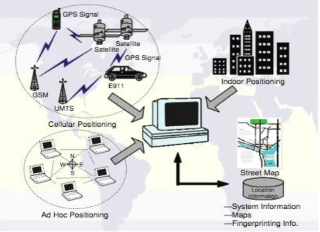
2.2.2 Network-based positioning methods
The modern smart phones can use up to three different methods to locate their position.
Satellite Positioning, Wi-Fi Positioning and Cellular Positioning as shown in figure 2.1.
Generally these positioning methods have different characteristics which can be measured by
the following criteria; accuracy, precision, power consumption, latency and availability
9
To meet higher accuracy requirements, more advanced mechanisms have been developed,
such as the Enhanced Observed Time Difference (E-OTD), Time Difference of Arrival
(TDOA), Advanced Forward-Link Trilateration (AFLT) and Uplink Time Difference of
Arrival (U-TDOA). To calculate the user’s position, most of these mechanisms utilize the
hyperbolic lateration mechanism, where the cellular base stations are utilized as fixed
position references similar to the satellites utilized in the GPS system (Blewitt, 2007). In
other methods, positioning calculations are performed by the network after collecting enough
information from the end-user device and close Base Transmitter Stations (BTS).
Network-based techniques have the advantage of using cellular signals in order to determine position
information. Therefore, they are able to determine the position of a device wherever it can
receive cellular signals, including indoors and within urban canyons. However,
network-based solutions are not able to supply the high levels of accuracy associated with GPS.
10
These solutions can accurately supply data up to approximately 50 meters in ideal conditions
which limits their use for certain positioning applications. To date, the U-TDOA method is
perceived as the best network-based positioning method (Blewitt, 2007). Dependence on the
network means that the user has to entirely depend on the network providers for positioning
(Winters et al., 2008).
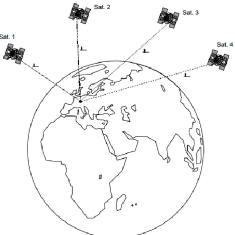
2.2.3 Global Positioning System (GPS) technology
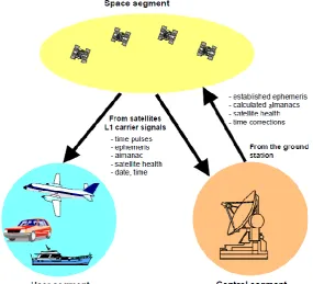
The GPS is a satellite based navigation system consisting of three segments. The space
segment is made up of made up 24+ network of radio emitting and receiving satellites placed
in to orbits as shown in figure 2.2. (Blewitt, 2007)
Figure 2.2: The three GPS segments namely; the space, user and control segments. The user segment may be an airplane, a ship, a car or a mobile terminal.
(Riaz, 2009).
GPS works in any weather condition, anywhere in the world, anytime and it’s free of charge
11
anywhere on the earth to calculate its own position through triangulation and trilateration.
The satellites are about 20,200 Km from the earth’s surface and have an orbital period of 12
hours. The control segment monitors the conditions of the satellites using a ground control
network of five control stations strategically placed around the earth; on Hawaii, Ascencion
island, Diego Garcia, Kwajalein and Colorado (Tsui, 2000).
The user segment consists of different types of GPS receivers; handheld or embedded on user
equipment like mobile phones, wrist watches, safety cameras, anti-theft lock systems, radios.
The constantly transmitted radio signal passes through clouds, glass and plastic but not
through most solid objects such as buildings and mountains (Blewitt, 2007). To determine
precise latitude and longitude position, the receiver measures the travelling time of the signal
between the satellites and itself and transforms it into a distance. The working of the GPS is
explained in detail in the next chapter, section 3.1.2.
2.2.4 Obtaining Position Data
There are many Application Programming Interfaces (APIs) available to a software developer
for obtaining the position data of a mobile terminal. An API lets users write scripts and
programs to manipulate virtual machines. APIs include intents, adapters, click on buttons,
dialogs, and shared preferences. It is high-level, easy to use, and practical for both script
developers and application programmers (VMware, 2006).The Programming API runs on the
Microsoft Windows and Linux platforms as well those written in C. The android platform
used in this study uses java coding and runs on several mobile phones. The APIs can mainly
be Handset based or network based. Handset-based APIs are accessed by software running on
12
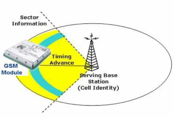
are accessed by web applications that send ‘network-initiated’ location requests to a server in
a cellular network, as shown in figure 2.3.
Figure 2.3: Cell ID with timing advance and sectored multidirectional antennas. The GSM
module and the sector information are also shown (Winters et al., 2008).
One programming language that has emerged as a platform-independent means of software
development for mobile phones is Android. Android is a software stack and mobile operating
system that includes the operating system for portable devices, middleware, user interface,
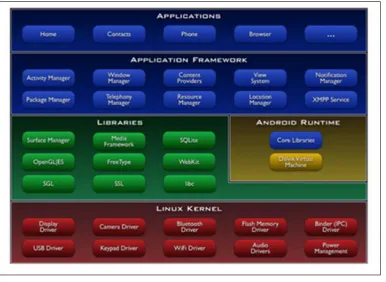
and a standard application (Symth, 2015). Android developers are able to write applications
in the Java language, a runtime library that can run the compiled byte code, figure2.4. In
addition, it provides the required application through the Android SDK to develop a variety
of tools and APIs. Android works on the Linux kernel and C / C + + libraries are included.
Android, unlike existing Java virtual machines, uses a Java application made of Dalvik
Virtual machine that runs on a separate process.
The GPS receiver requests for its location, the application tries to calculate its location
13
received is called the time to first fix (TTFF). When a high-accuracy fix is first requested
from a phone with Assisted GPS technology, the phone will attempt to utilize assistance
information from the network that lessens the time to first fix. If the GPS hardware cannot
obtain a fix that meets the provided accuracy criteria within a given timeout period, then the
Java Location API will usually provide Cell-ID information for the cellular area that is
currently serving the device along with a note that a high accuracy GPS fix was not attainable
(Blewitt, 2007). If a GPS fix can be obtained, it will be returned to the user along with other
information, including the estimated accuracy of the GPS fix based on the number of
available satellites as well as other positioning data.
Figure 2.4: A construction of android starting with the application development, framework, libraries and the runtime environment stacked over the Linux kernel
(Sun microsystems, 2007).
The second way an application can request position data is to register a location listener with
the location provider. A location listener is a mechanism that monitors the device’s location
14
intervals such as every 30 seconds. This method is ideal especially for this study as the
application requires continuous updates on the position of the device, such as tracking or
navigation applications. Since the update interval is defined by the application, location
updates can be provided as frequently as once per second or as frequently as the underlying
hardware and operating system can allow, whichever is less frequent. If the device is
informed that the application is going to require positioning data over an extended period of
time, it can optimize power consumption thereby making use of the location listener more
efficiently than repeated calls to the getLocation function (Winters et al., 2008).
2.3 Databases
Databases are very important in storing the data obtained from the GPS and availing it
whenever the mGuide application is determining distances between different positions of the
user. SQLite is an Open Source Database which is embedded into Android. SQLite supports
standard relational database features like SQL syntax, transactions and prepared statements
(Lee, 2012). In addition it requires only little memory at runtime. This is in contrast to
standard databases which requires large memory and are hosted externally. SQLite is a
software library that implements a self-contained, server less, zero configuration, and
transactional SQL database engine. SQLite is the most widely deployed SQL database engine
in the world (SQLite, 2012). The database that is created for an application is only accessible
to itself; other applications will not be able to access it. This is great advantage as the data
cannot be manipulated by other people unless they access the mobile phone; this ensures the
security of the data stored. Once created, the SQLite database is stored in the
data/data/<package_name>/databases folder of an Android device.
15
2.4 Navigation Algorithms
These are the algorithms used to provide the navigation software with the alternatives of the
routes or paths which are followed from the origin to destination. Examples of navigation
algorithms discussed in this section include; map-matching, semi-deterministic, fuzzy-logic
and the routing algorithms. The difference amplification algorithm (DAA) used in this work
is discussed briefly but will be discussed in detail in the next chapter.
2.4.1 Map-matching methods
Map-matching (MM) techniques integrate, positioning data with spatial road network data
have been developed in order to provide the real-time, accurate and reliable positioning
information required by many Intelligent Transport Services such as route guidance, fleet
management and accident emergency response (Chabini and Lan, 2002). The problem of
resolving spatial ambiguities has been widely studied over the years. The following
map-matching algorithms are described with different levels of complexity ranging from simple
geometric techniques to complex, advanced approaches. The difference amplification
algorithm (DAA) is also explained.
2.4.2 Semi-deterministic map-matching
This model assumes that the vehicle has an initial location on a roadway and a given
direction of travel. Conditional tests are applied to determine whether the vehicle is traveling
on the known road by comparing turns from the vehicle location to a segment of the digital
road map (Chou et al, 1998). A correction is performed whenever the heading of the vehicle
changes. However, for this technique to work, the vehicle is generally assumed to follow a
predetermined road. There is considerable uncertainty when the vehicle travels off-road
16
2.4.3 Fuzzy logic map-matching
Fuzzy logic is an effective way to deal with tasks that involve qualitative terms and concepts,
vagueness, and human intervention. If the difference between the orientation of the roadway
segment and the heading of the vehicle is small, then resemblance between the vehicle travel
path and the candidate route is high. The algorithm identifies the roadway on which a vehicle
is traveling by comparing C-measures associated with each candidate roadway (Hightower
and Schilling, 2001). These measures are membership functions that represent the certainty of
the existence of a vehicle on a specific roadway. After the roadway is identified, the
algorithm determines the vehicle position on the roadway by orthogonal projection. The
algorithm requires the distance between the vehicle’s GPS coordinates and its projected
position on the roadway to be small. Furthermore, the shape of the roadway must be similar
to the trajectory of the vehicle.
Figure 2.5: Fuzzy logic map matching: A vehicle travelling along a buffered route; e1 e2, e3, e4 being the possible turns within the route (Greenfeld, 2002.
Three fuzzy rules used to evaluate the possibility of mapped routes being the ones actually
travelled on. The rules are; heading comparison, road resemblance, and verification of the off
road vehicles. Test results with simulated data indicate that the algorithm is capable of
achieving high accuracy (Quddus and Oommen 2006). The proposed algorithm employs an
17
the vehicle location on the selected link. Although the algorithm was tested successfully in
different road networks, the authors consider that future evaluation of the algorithm is
required under urban conditions. The main disadvantage of map- matching methods is that of
initial map matching process. The process of identifying the correct segment near a junction
may return an error indicating no road segment when they actually exist, figure 2.5 (Tsui,
2000).
2.5 Outdoor navigation applications
There are several applications which have been developed designed for the visually
challenged persons. This section discusses some of them including Wayfinder, Maverick,
google navigation and Georgie smart phone. Each of this application is designed to meet a
specific need of the user. Georgie smart phone is fitted with a screen reader to enable the user
listen to messages and content in social media. The other application uses GPS and various
maps such as google maps to locate the user and provide various services based on location.
mGuide combines recorded voice instructions, speech engine, GPS and open street maps to
provide accurate turn by turn outdoor voice guidance.
2.5.1 Wayfinder Access
Wayfinder access is a navigation system for mobile phones specially developed for visually
impaired persons. It was developed in partnership with other companies which have speech
synthesis software, such as Talks from Nuance Communications or Mobile Speak from Code
Factory. It offers a robust audible pedestrian navigation experience. It has several useful
features for the visually impaired; continuous proximity scanning of your immediate area
helps the user discover intersections and other key points of interest. It also offers real time
18
vicinity (Run, 2004). Wayfinder Access is compatible with all Symbian series 60 mobile
phones, which run on the GSM cellular network and smart phones with Microsoft Windows
Mobile phones. It only operates on a mobile phone equipped with a screen reader. The user
needs to establish an Internet Access Point on the phone and requires Google maps for its
operation
2.5.2 Maverick: GPS Navigation
The application uses offline maps and GPS even without an internet connection. It is used
for hiking, boating, geocaching and other outdoor activities. It has multiple global and
regional online maps, including: Bing, Yandex, Open Street Maps and Ordnance Survey
maps (Rob, 2009). The maps are automatically cached for offline use. The user can see all the
nearest locations from foursquare and footprints. It has a trackback functionality which
guides a user along a previously recorded track with compass pointing to a nearest point. A
new track can be recorded at the same time. All waypoint stored in the Keyhole Mark-up
Language (KML) file and can be viewed and edited in Google Earth. This application lacks
voice guidance hence it’s not adapted for the VCP.
2.5.3 Satellite Navigation
Satellite navigation is an application service from technology company Google, available for
smart- phones on the Android and iPhone operating system. Google Maps Navigation (Beta)
is an internet-connected GPS system that provides turn-by- turn voice driving directions as a
feature of Google maps for mobile. The turn-by turn, voice guided navigation allows the user
to listen for indications during driving period to prevent detraction (Zogg, 2009). The mGuide
19
on it instead of typing the name of destination or speaking it out may lead to wrong
directions.
2.5.4 Smartphone, Georgie
Georgie, a Smartphone designed for VCP was developed by not-for-profit social enterprise
Screen reader and available through exclusive partners Sight and Sound Technology (SST)
(Pascual, 2009). The smartphone includes applications built specifically to help VCPs
navigate day-to-day obstacles like catching a bus and reading printed text. Tasks more
commonly associated with smart phones like using Twitter, reading text messages and taking
a picture have also been updated to be much easier to use and accessible to visually impaired
people for the first time (Tookey, 2012). The application uses a screen reader and lacks
functionality for turn-by- turn voice navigation.
Three of the four applications discussed above do not meet the specific need of turn by turn
outdoor voice guidance to the user. They are the smart phone Georgie, Maverick and the
Wayfinder access. The fourth application discussed has a slower response time and does not
guide the user to a precise destination. The mGuide application has a faster response time of
six seconds and the destination is pinpointed on the map by simply zooming in and tapping
out. The mGuide application has over fifty recorded, local language voice clips which the
20
CHAPTER THREE
THEORETICAL BACKGROUND
3.1 Introduction
This chapter discusses the following theoretical concepts: GPS signal transmission, reception
and use in positioning; the use of clock bias in determination of distance; determination of
position in 3D space; use of SMS and the mGuide application. The difference amplification
algorithm (DAA) used in mGuide will be explained and its use justified.
3.2 Determination of the location of a mobile terminal
There are three common classes of positioning techniques that can be utilized to obtain the
mobile terminal’s geographic information: Device-based methods, cellular network-based
methods and hybrid methods. This chapter will discuss each of the technique and show why
GPS is the most accurate in outdoor navigation. The mathematical formulas fundamental in
understanding how GPS works will be given.
3.2.1 Device-based positioning methods
The device based positioning method is based on GPS technology and utilizes the hardware
and software that resides in the end-user device to determine the position of the device. Many
mobile phones and certain PDAs are equipped with embedded GPS receivers that receive the
signals from satellites. The main advantage of GPS is that very highly accurate location data
can be obtained within 10 meters of accuracy in ideal scenarios, as shown in table 3.1. This
level of accuracy allows the development of real-time applications that interact with the users
based on their current position. For example, vehicle navigation systems that provide the
21
There are however some disadvantages of GPS that exist. First, since the GPS transmissions
from the satellites are very weak, the device must have a clear view of the sky to receive the
transmissions used to calculate its position. This means that pure GPS positioning solutions
do not work well indoors or in situations where radio signals may be interrupted, such as
during severe weather or in “urban canyons” areas surrounded by many tall buildings.
Table 3.1: Location technologies for cellular phones (Paikannussanasto, 2002)
Technology Type Accuracy
Cell-ID Network 100 m-3km (Depends on
the size of the cell)
Cell-ID + Timing Advance Network Network band size configurable.
Default is 500 m Time of Arrival (TOA) Network 250-350 m Angle of Arrival (AOA) Network 100-200 m Advanced Forward Link
Trilateration (AFLT)
Network 50-200 m
Enhanced Observed Time Difference (EOTD)
Network 50-200 m
Uplink Time Difference of Arrival (U-TDOA)
Network 40-60 m
Global Positioning System Device 10-50 m Assisted Global Positioning System
(A-GPS)
Hybrid 5-30 m
Secondly, GPS devices can take a significant amount of Time-To-First Fix (TTFF) of up to 2
minutes or more when the GPS hardware is first turned on. This scenario, referred to as a
“cold-start,” results from the GPS hardware having too many radio channels to determine
what satellites may be in view (Winters et al., 2008).
In this work, GPS satellite positioning is used to locate the mobile phone because it has the
22
a) It is free for anyone with a GPS receiver to use. It renders the user totally independent
of the mobile network with respect to positioning.
b) It provides 10-50 meter accuracy, if the terminal has an access to three or more
satellites as opposed to the cell-based method whose accuracy can be 2-3 kilometers
especially in rural areas.
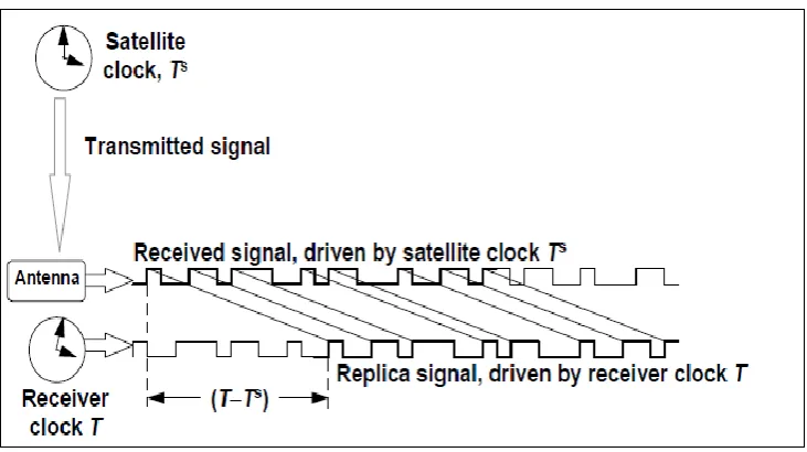
3.1.2 GPS signal transmission and reception
A GPS signal is transmitted from a satellite to a receiver on the ground which may be
embedded in the mobile phone. Information is encoded in the form of binary bits on the
carrier signal using phase modulation. It starts as a voltage which oscillates at the
fundamental frequency 10.23 MHz then transmitted by antennas which radiate the signal in
the form of an electromagnetic wave. The receiver also generates an electronic replica of the
received signal as shown in Figure 3.1 (Blewitt, 1997). By getting the difference in time
between when the GPS signal from the satellite was sent and when it is received, the actual
observation to the satellite(s) can be written as;
P
T
T
c
S
S
(3.1)
Where T is the reading of the receiver clock, S
T is the reading of the satellite clock and C is
the speed of light (in a vacuum) = 299792458 m/s. The satellite clock reading is transmitted
as part of information encoded in the form of binary bits on the carrier signal using phase
modulation (Tsui, 2000). The modeled observation can be developed by setting the clock
time T equal to the true receive time (t) plus a clock bias (
), for both the receiver andsatellite clocks:
23
T
S
t
s
s (3.2b)Substitution gives the pseudo-range as a function of the true time the signal is received:
P
t
t
t
c
S S
S
(3.3a)
S S
c
c
c
t
t
(3.3b)
S S
S
c
c
t
t
,
(3.3c)Where
S
t
,
t
S is the range from receiver (at receive time) to the satellite (at transmit time).This model is simplified and will give an accuracy of 10- 15 meters. Since, the satellites are
constantly moving relative to observers on the Earth, effects predicted by the Special and
General theories of Relativity must be taken into account and there corresponding equations
included to achieve the desired high level of accuracy to centimeter level. From Pythagoras
theorem (Pogge, 2016);
ρs(t, ts) = √(xs(ts) − x(t))2+ ys(ts) − y(t))2+ zs(ts) − z(t))2 (3.4)
24
Figure 3.1: Aschematic diagram showing how the GPS pseudo-range observation is related to the satellite and receiver clocks (Blewitt, 1997).
The navigation message allows the computation of the satellite position
x
S,
y
S,
z
S
and thesatellite clock biasS. Therefore, there are only 4 unknowns; the receiver position (x, y, z)
and the receiver clock bias
. The satellite position must be calculated at transmission time (t)and this is important because the satellite range can change as much as 60 meters from the
time the signal was transmitted, to the time the signal was received, approximately 0.07
seconds later. If the receiver time were used instead, the error in computed range could be
tens of meters. Starting with the receiver time (t), the transmit time can be computed by an
iterative algorithm known as “the light time equation,” which can be written as follows:
c t t t t c t t t t T t t S S S S S S S 1 , 2 0 , 1 0 (3.5)Where
S
t
,
t
S is the range to the satellite position at each step, t, the receiver time, T is the25
The above algorithm starts with the true receive time, which requires the receiver clock bias.
Usually, the bias is not known in advance but for most receivers it never gets larger than a
few milliseconds (beyond which, the receiver will reset its clock). If zero is assumed in the
above computation, the error produced is a few meters, which is much smaller than typical
point positioning precision of approximately 50 meters with selective availability switched on
(Blewitt, 1997). Using the above notation, the pseudo-range to each satellite in view of the
receiver can be written as:
1 2 1 2 1 2
12 11
c c z z y y x x
P (3.6a)
2 2 2 2 2 2
12 22
c c z z y y x x
P (3.6b)
3 2 3 2 3 2
12 33
c c z z y y x x
P (3.6c)
4 2 4 2 4 2
12 44
c c z z y y x x
P
(3.6d)
Where ρ1, ρ 2 , ρ 3 and ρ 4 are the pseudo-ranges to each of the four satellites, (x1 –x) , (x2–x),
(x3 –x ) and (x4 –x ) gives the range in the X coordinate ; (y1 –y) , (y2–y), (y3 –y) , (y4 –y )
gives the range in the Y-cordinate and (z1 –z) , (z2–z), (z3 –z ) and (z4 –z ) are the ranges to
the four satellites from the receiver in the Z coordinate respectively.
1,
2,
3 and
4 are the26
Figure 3.2: Determination of in 3-D space. The navigation message allows the computation of the satellite position
x
S,
y
S,
z
S
and the satellite clock bias (Blewitt, 1997)3.1.3 Converting Cartesian to ellipsoidal position coordinates
The Figure 3.3 shows the ellipsoidal coordinates (𝜑, λ, h), which are used rather than
Cartesian coordinates (X, Y, Z).The ellipsoidal coordinates 𝜑, corresponds to latitude, λ to
longitude and h to the ellipsoidal height, that is, the length of the vertical P line to the
ellipsoid.
27
Cartesian and ellipsoidal coordinates can be converted from the one representation to the
other. As 𝜑 and h show up on the right side of the following equations, these equations have
to be evaluated iteratively for an accurate solution.
Where (𝜑, λ, h) are the ellipsoidal coordinates and RN is the radius of the ellipsoid.
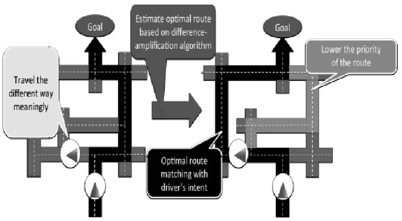
3.1.4 Route recommendation based on difference amplification algorithm (DAA)
Difference Amplification algorithm (DAA) is a method that can estimate driver’s intent and
recommend another route matching with the driver’s intent when choosing a different route
from the route originally recommended by car navigation system, Figure 3.4. Furthermore,
the destination is assumed to be fixed even if driving route is changed; because the driver’s
destination does not change when the driver uses route recommendation function of car
navigation system, (Tanaka et al., 2003). The DAA is a method that estimates what the user
originally demand based on comparing and amplifying difference between “what the user
selected” and “what the user did not select”. Thus, it tries to recommend new route matching
with user’s intent by re-calculating traveling cost of each route based on difference (3.7a) (3.7b)
(3.7c)
(3.7d)
28
amplification between “the route that navigation system has not recommended but the user
has travelled” and “the route that the user has not travelled but navigation system has
recommended”.
Figure 3.4: Difference Amplification algorithm method that estimates what the user originally has set as the destination and amplifying difference between that and “what the user did not select” (Tanaka et al., 2003).
Figure 3.5 shows an example of traveling cost and the shortest route. The nodes are
corresponding to intersections, links are corresponding to roads between intersections, and
numbers of links are corresponding to traveling cost on the links. The 10 traveling cost can be
regarded as 10 minutes driving time. The route (1 → 3 → 9 → 12 → 15) corresponds to the
shortest route from node 1 to node 15. If a driver traveling from node 1 to node 15 drives on
the route (1 → 2) contrary to recommended route. In such a case, conventional car navigation
system often recommend the shortest route from node 2 to node 15, and then the system may
recommend the route(2 → 3) to the driver because the shortest route from node 2 to 15 is the
29
route (1 → 3) if s/he want to move to node 3. Therefore, it is not appropriate to recommend
the route (2 →3) if the driver have selected the route (1 →2) intentionally (Laasonen, 2005).
Figure 3.5: Traveling cost of each road and the shortest route. Node 1 is the origin while node 15 is the destination. Nodes 2 to 14 are the possible routes the user can
choose (Tanaka et al., 2003).
The cost of a route estimated that driver wants to travel on it gets bigger than the original
cost. The algorithm thus, calculates the shortest route after re-estimating based on DAA. The
method can recommend the optimal route matching with user’s intent without going back to
original recommended route by means of rerouting the user through the shortest path
available.
3.2 Short Message Service (SMS)
SMS is a technology that enables sending and receiving of short messages between mobile
phones. It is a technology that has been used extensively in today’s wireless world. It was
originally designed for person-to-person messaging service where a sender could use his
mobile phone to send a brief text message to a recipient. This is achieved through the use of
Attention (AT) commands. They are a set of instructions used for controlling mobile phone
30
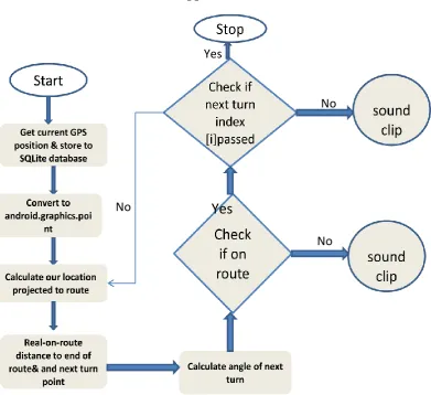
3.3 A flow chart for the mGuide Application
Figure 3.6: A flow chart diagram for the mGuide application, used in this work, showing the
flow of activities starting from the obtaining of the GPS position to speaking of voice commands when a wrong turn is made.
Figure 3.6 above shows the flow chart for the mGuide application. The GPS gets the current
locations of the phone and stores them in the SQLite local database. The database then
converts the coordinates into graphical format for display on the map. The destination is also
converted to graphical format. The DAA is used to get the shortest distance between the two
points projected to the mapped routes; calculates and displays the angle to the next turn along
the route and guides the user through a turn by turn to the destination. The navigation is real
time hence, the application keeps on updating its current location and if the user deviates
from the route, a warning sound clip is played and the DAA reroutes the user to the
destination using an alternative route.
No No
Yes
Yes
31
CHAPTER FOUR
RESEARCH METHODOLOGY
4.1 Introduction
This chapter focuses on the following aspects of mGuide application developed in this work;
the code used, the main classes for the determination of location and distances, use of SQLite
for the determination of route statistics and the use of query builders. The chapter commences
with the designing of the mGuide application.
4.2 Design of the mGuide Application
An Android application is a collection of tasks, each of which is called an activity. Each
activity is designed to fulfill a unique purpose and user interface (Darcey and Conder, 2010).
The design of the application is simplified with three screens to perform the vital
functionalities of the application. The first screen is the Splash which is the startup screen,
with the application logo and plays a sound clip welcoming the user to the application as
shown in Figure 4.1.
32
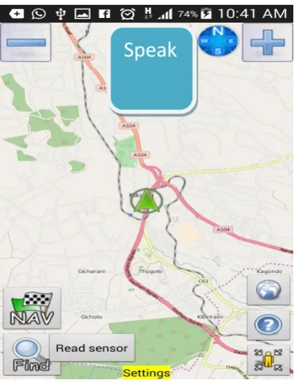
The Menu screen is the home page with the map used in the setting of destination.
The destination can be set using the speak button where the VCP is prompted to speak
onto the phone’s speaker for a google search of the desired destination. Alternatively,
another person can help in setting the destination by zooming out on the map and
identify the specific destination as shown in Figure 4.2. The settings button opens to
settings screen which displays instructions for how to set the destination and changing
the appearance of the menu screen. The instructions are read out by invoking the Text
to Speech engine.
Figure 4.2: The Menu Screen showing the ‘speak’, ‘zoom’, ‘read sensor’, ‘NAV’and ‘settings’ buttons.
The Navigation screen is where the user is guided through a turn by turn voice guidance
from the origin to the destination. The voice is a series of recorded voice commands and
activated continually till the user reaches the set destination in the menu screen. The screen is
33
activated by pressing the Navigation button shown in Figure 4.2. The design of the
Navigation screen is as shown below in Figure 4.3 shown below
Figure 4.3: The Navigation Screen showing the distance remaining to destination.
4.3 The Implementation of the mGuide
The mGuide application designed as shown was implemented mainly using three software
parts. The initial part was the receiving of GPS coordinates and converting them into location
on a map, then the DAA was used to guide the user through each portion of the route at
regular intervals. The voice clips for warning the user in case of lost route were also recorded
and added to the software. The developed application was compared with handheld GPS
device to check on precision, accuracy and reliability.
4.3.1 Block Diagram of the mGuide Application
A complete block diagram for the system is shown in figure 4.4. The application was first
implemented on a computer then the Android Package File (APK) installed onto the user’s
phone. The mGuide application was installed on an android supported mobile phone with an
34 kjnkn
Figure 4.4: The system architecture of the designed navigation application, showing the mGuide installed the open street maps servers, and in case of wrong turn an SMS is sent to
guardian’s phone.
Java language was used for back-end coding and android programming was used for user
interfacing. Android is platform independent as it uses Linux Kernel as an abstraction layer
between the application and the mobile hardware. The Android Software Development Kit
(SDK) provides a powerful development and debugging tools for software development. The
android emulator supports many hardware features such as; an internal memory, a 16-bit
Liquid Crystal Display (LCD), a camera and other sensors like an accelerometer. The
emulator however does not have GPS sensors for loading map tiles. Therefore, the testing
was done on an actual device: an Android phone running on Android operating system.
The GPS satellite system was used by the mobile phones with embedded GPS chips for the
purpose of geo-location data. The maps used in this application were downloaded in real time
from the open street map servers after obtaining a cloudmade key from their website. The
DAA was incorporated in the SQLite 3 database in the phone for turn by turn voice guidance.
GUARDIAN
PHONE
Internal SQLite 3 database
Lost route (send text)
tiles Route
statistics Position data
Loading map tiles
Reroute
35
The voice commands were studio recorded and uploaded to the application’s resources
folder. A total of sixty five voice commands were recorded for various route commands. The
voice commands were recorded in MP3 format in both English and Kiswahili languages.
4.3.2 The mGuide code
The Java program, being an object oriented programming, is divided into packages which are
further divided into smaller units called classes to execute a specific task. The mGuide
application has twenty packages developed over time to accomplish various aspects of the
whole project. The rest of the packages are listed in the appendix E. Here is a description of
some of the main classes.
The LocationManager method in the MainActivity class offers background service for
querying the current location of the mobile terminal and storing it in the mobile database. The
SQLiteHandler method is used to insert the position data into the database. The
onLocationChanged method, is called when a new location is found by the network location
provider. It updates the application with the new location information on regular intervals and
calculates the distance to destination using the calculateDistance method. The voice engine
is called through the Text to Speech (TTS) class which is called via the Timer method after a
specified time interval of about 30 seconds to inform the distance to destination. The
MainActivity class extends FragmentActivity which loads the maps and implements
LocationListener. The code segment was tested using the real device and was found to load
maps and calculate distances to destination progressively at the same giving turn by turn