SIMULATION MODEL FOR COMPATIBILITY OF CO-SITED IMT-ADVANCED AND POINT TO MULTIPOINT SERVICES
Z. A. Shamsan and T. A. Rahman
Wireless Communication Center Faculty of Electrical Engineering Universiti Teknologi Malaysia (UTM) Malaysia
Abstract—3.5 GHz fixed wireless access system is a
point-to-multipoint wireless technology providing broadband services. In this paper, point-to-multipoint fixed cellular service network structure such as Local Multipoint Distribution (LMDS) service is proposed to share same network area and frequency band (3400–3600 MHz) with the fourth generation of mobile (IMT-Advanced) represented by mobile Worldwide Interoperability for Microwave Access (WiMAX) service on base of co-sited systems. As a result of space and frequency domain sharing, harmful interference probability may be transpired between the two services. Different network cell sizes and different channel bandwidths were considered in dense urban area to investigate the intersystem interference effects based on the average interference to noise ratio INR as a fundamental criterion for coexistence and sharing coordination between different systems. Adjusting of antenna discrimination loss is also proposed to facilitate the frequency efficiency and accomplish frequency sharing.
1. INTRODUCTION
LMDS or Local Multipoint Communications Services (LMCS) is an immediate extension of MMDS (Microwave Multipoint Distribution Systems) more focused on residential market services, and may eventually replace it. LMDS are delivering broadband services from a central transmitter or base station to fixed customer stations mounted on individual buildings, blocks of apartments, or buildings
of residential as well as business customers within its cell size [1]. Spectrum for these systems has been allocated at various frequencies from 2500–38000 MHz (2.5–38 GHz) [2]. Due to scarcity of the frequency spectrum on one hand and the drastic growth demand for wireless communications on the other hand, many bands are allocated for more than one radio service and therefore the sharing is necessity. Because of all that, International Telecommunication Union for Radiocommunication (ITU-R) Working Party 8F (WP 8F) has allocated the frequency band 3400–3600 MHz for International Mobile Telecommunication-Advanced (IMT-Advanced) on co-primary basis with fixed services. This means that intersystem interference will be occurred and cause performance degradation [3, 4] within C-band (3400-4200) which is characterized by excellent propagation features [5, 6].
There are several studies have been done to investigate the interference using carrier to interference ratio C/I within the same system [1, 5–9]. Our study will focus on intersystem interference and compatibility issue between two systems using average interference to noise ratio INR as coexistence and interference protection criteria between systems.
Some recent coexistence studies were carried out in the band 3.5 GHz [3, 4] between IMT-Advanced service and FWA as a point to point service in different terrestrial areas, different clutter loss and different intersystem interference scenarios. In this paper, we are proposing that FWA is a point to multipoint (P-MP) service uses an LMDS service structure in the band 3500 MHz [10] and IMT-Advanced service will share the same tower with point to multipoint service on co-sited systems basis. Different network cell sizes will be taken into account to evaluate coexistence and also to determine the minimum separation in spectral frequency and geographical space domains. In our simulation, spectral efficiency by modifying the off axis angles will be examined at different bandwidths by determining the minimum frequency offsets from the carrier frequency within dense urban area for a network cell size of 6×6 kms. WiMAX is the candidate technology for IMT-Advanced systems; therefore some parameters of WiMAX will be used instead of IMT-Advanced which are not officially released.
Figure 1. Establishing of IMT-Advanced and fixed services.
2. OPERATION NETWORK DESCRIPTION
According to [11, 12] LMDS system network structure can be configured as in Fig. 1. INR conditions link budget directions are obtained. A frequency-sectored LMDS system applying 4-frequency and 90◦ sectorization with Time Division Multiple Access (TDMA) are investigated in the 3.5 GHz band, whereas IMT-Advanced employs Orthogonal Frequency-Division Multiple Access (OFDMA). The frequency sectorizations and the dominant interference situations are depicted in Fig. 3. The frequency duplex type is Time Division Duplex (TDD) for IMT-Advanced whereas LMDS employs Frequency Division Duplex (FDD). The different frequencies (f1,3, f2,4, f3,1, and f4,2) are signed by different color shades such that (fx, y) means
(fLMDS frequency,IMT-Advanced frequency) as shown in Figs. 1–3. It is
Figure 2. Sectors frequencies used for fixed and IMT-Advanced services.
Figure 3. The simulated scenario between IMT-Advanced and fixed
services.
space sectored antennas.
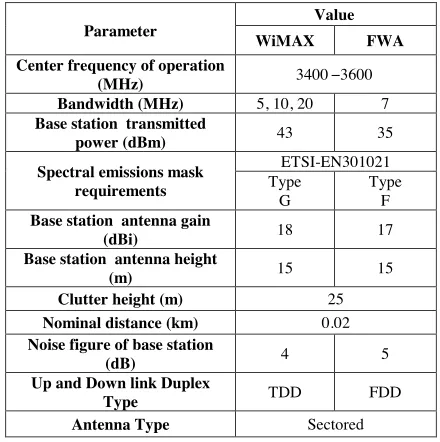
Table 1. WiMAX and fixed systems parameters.
Parameter
Value
WiMAX FWA
Center frequency of operation
(MHz) 3400 3600
Bandwidth (MHz) 5, 10, 20 7
Base station transmitted
power (dBm) 43 35
Spectral emissions mask requirements
ETSI-EN301021 Type
G
Type F
Base station antenna gain
(dBi) 18 17
Base station antenna height
(m) 15 15
Clutter height (m) 25
Nominal distance (km) 0.02
Noise figure of base station
(dB) 4 5
Up and Down link Duplex
Type TDD FDD
Antenna Type Sectored
system. As seen from Fig. 3 that IMT-Advanced antenna at base station 9 (B9) suffers from three intersystem interference signals (B1,
B7, and B3) (the intra-system interference is not considered here). Therefore, the separation distance between the interferer B1 and the victim BS (B9) antenna is (√((SeC)2+ (SeC)2)×4) km, whereas B3 andB7 have an equivalent distance to the victimB9 of (4×SeC) km. All geographical separation distances between every effective interferer base station and the victim base station are listed in Table 2. All FWA links utilize directional antennas, however, antenna patterns are not considered except for the maximum antenna gain in link budget, so it is assumed they are considered as omnidirectional in order to study the worst case scenario.
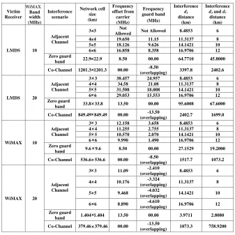
Table 2. Frequency offset, guard band, and the distance between interferer and victim in various coexistence scenarios and different network cell size.
Victim Receiver Band width (MHz) Interference scenario Network cell size (km) Frequency offset from carrier (MHz) Frequency guard band (MHz) Interference d1 distance (km) Interference
d3 and d7 distance (km)
LMDS 10
Adjacent Channel
3 3 Not
Allowed Not Allowed 8.4853 6
4 4 19.650 11.15 11.3137 8
5 5 18.126 9.626 14.1421 10
6 6 16.858 8.358 16.9706 12
Zero guard
band 22.9 22.9 8.50 00.00 64.7710 45.8000
Co-Channel 1201.3 1201.3 00.00 -8.50
(overlapping) 3397.8 2402.6
LMDS 20
Adjacent Channel
3 3 38.457 24.957 8.4853 6
4 4 34.58 21.08 11.3137 8
5 5 31.508 18.008 14.1421 10
6 6 29.053 15.553 16.9706 12
Zero guard
band 33.8 33.8 13.50 00.00 95.6008 67.6000
Co-Channel 849.49 849.49 00.00 -13.50
(overlapping) 2402.7 1699.0
WiMAX 10
Adjacent Channel
3 3 12.158 3.658 8.4853 6
4 4 11.255 2.755 11.3137 8
5 5 10.570 2.070 14.1421 10
6 6 9.990 1.490 16.9706 12
Zero guard
band 9.6 9.6 8.50 00.00 27.1529 19.2000
Co-Channel 536.6 536.6 00.00 -8.50
(overlapping) 1517.7 1073.2
WiMAX 20
Adjacent Channel
3 3 11.09 -2.410
(overlapping) 8.4853 6
4 4 10.176 -3.324
(overlapping) 11.3137 8
5 5 9.468 -4.032
(overlapping) 14.1421 10
6 6 8.890 -4.610
(overlapping) 16.9706 12 Zero guard
band 1.404 1.404 13.50 00.00 3.9711 2.8080
Co-Channel 379.46 379.46 00.00 -13.50
(overlapping) 1073.3 758.9200
WiMAX
the carrier frequency:
M ask Attenuation(∆f) =af+b (1)
wherearepresents the amount of attenuation in dB in the segment,f
3. SYSTEMS SHARING ANALYSIS
The two systems can be coexisted if the sharing fundamental criterion is achieved. The coexistence and interference protection criteria can be defined as an absolute interference power levelI, interference-to-noise power ratio INR, or carrier-to-interfering signal power ratioC/I [17].
In this paper, and according to ITU R F. 758-2, anINRof−6 dB is the fundamental criterion for coexistence and intersystem interference coordination [15, 18], and this can be justified as in Appendix A:
INR =I[dBm]−N[dBm]≤α (α=−6 dB) (2) In case of point to multipoint system network, there are more than one interference signal will affect the victim receiver base station as shown above in Fig. 3, and thus:
INR = Itotal[dBm]−N[dBm]≤α (3)
Itotal = M
j=1
IBj(∆f)
M (4)
where Itotal represents the total interference received power at victim
receiver in watt andM is number of the effective interferer base stations on victim receiver. In our case, there are three effective interference base stations (B1,B3, and B7).
Itotal=
3
j=1
IBj(∆f)
3
= IB1(∆f)[watt] +IB3(∆f)[watt] +IB7(∆f)[watt]
3 (5)
IBj(∆f)[watt] = 10((IBj(∆f)[dBm]/10)×10
−3)
(6)
IBj(∆f)[dBm] =P t[dBm]+Gt[dBi]+Gr[dBi]+M askAtt(∆f)[dB]
+Corr band[dB] +Lossesdj[dB] (7)
Corr banddenotes correction factor of band ratio and depends on bandwidth of interferer and victim receiver, where,
Corr band=
−10 log10
BWinterferer
BWvictim
dB if BWinterferer≥BWvictim
0 dB if BWinterferer< BWvictim
(8) The interference signal power is from different base stations and it mainly depends on spectral mask and distance between each effective interferer base station and the victim receiver. The Losses are the propagation model effects and include free space and clutter loss attenuation and for our considered frequency (3500 MHz), the Losses formula becomes:
Lossesdj[dB] = 103.33 + 20 log10(dj) +10.25e−dk 1−tanh 6
h
ha−
0.625
−0.33 (9) wheredj denotes distance between each interferer base stationBj and the victim receiver,dk is the distance (km) from nominal clutter point
to the antenna, h is the antenna height (m) above local ground level, and ha is the nominal clutter height (m) above local ground level.
Therefore, Eq. (4) becomes:
Itotal=
3
j=1
IBj(∆f)
3
=
10((IB1(∆f)[dBm]/10)×10 −3
) + 10((IB3(∆f)[dBm]/10)×10−3)
+10((IB7(∆f)[dBm]/10)×10−3)
3 (10)
For deriving the thermal noise floor (N) of receiver in dBm, it depends on bandwidth and noise figure of victim receiver:
N[dBm] =−114 +N F + 10 log10(BWvictim) (11)
where NF is noise figure of receiver in dB and BWvictim represents
victim receiver bandwidth in MHz. The interference to noise criterion can be expressed as a ratio in (12) or as a dB in (13):
INR = Itotal
10((N[dBm]/10)×10−3) ≤0.26 (12)
INR[dB] = 10 log10
Itotal/10−3
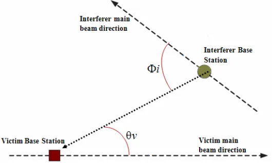
Figure 4. Interference scenario for one interferer base station to victim station with off axis angles Φiand θv.
4. ANTENNA DISCRIMINATION LOSS
Antenna discrimination is the differential gain compared to maximum for an antenna in the specified direction; usually, masks are provided for the main lobe, the first sidelobe, and other sidelobes [19]. Antenna discrimination loss is resultant from the antenna direction of the interferer transmitter and victim receiver services which is dependant on the off axis angles Φi and θv as in Fig. 4. Therefore, as it is seen from Fig. 4, the interference signal emitted from one interferer base station (it can be supposed that the same scenario is applied for the other effective interferers signals) impacts one victim base station. Any interferer signal goes under different losses which include propagation path loss, dense urban clutter loss, and antenna discrimination loss. As a result of presence more than one interferer signal (multi interferers) will influence the other receiver service, the interferer signals power from the aggressive base stations can be estimated as an average received power.
5. RESULTS AND DISCUSSIONS
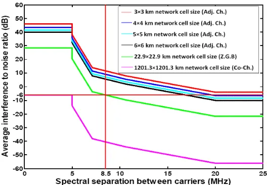
Figure 5. Interference within different network cell size (1×1 kms up to 6×6 kms) from 10 MHz WiMAX to 7 MHz FWA.
Figure 6. Intersystem interference scenarios in different network cell
Figure 7. Intersystem interference scenarios in different network cell size from 20 MHz WiMAX to 7 MHz FWA.
5.1. Intersystem Interference When WiMAX is the Interferer Service
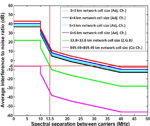
Figures 5–7 show the external interference effects into 7 MHz fixed serviceB9 from 10 MHz and 20 MHz WiMAX service in terms ofINR
Figure 8. Intersystem interference scenarios in different network cell size from 7 MHz FWA into 10 MHz WiMAX.
The minimum network cell size for co-channel is 1201.3 × 1201.3 kms and 849.49×849.49 kms for 10 MHz and 20 MHz WiMAX channel bandwidth, correspondingly. These values are too large to be practically realizable. The detail analysis of how to share co-channel frequency has been done in further Section.
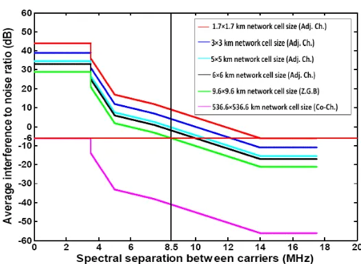
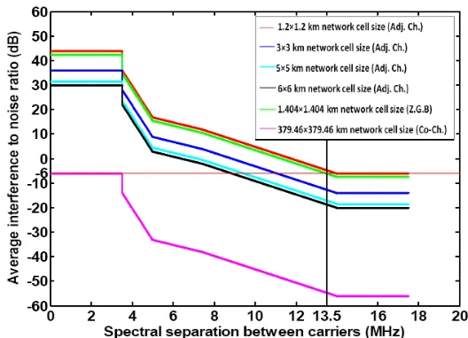
5.2. Intersystem Interference When WiMAX is the Victim Service
It can be seen from Figs. 8 and 9 that the largest frequency separation is 14 MHz because of the interferer has fixed channel bandwidth. In comparison with the interference from WiMAX service, the minimum network cell sizes here are smaller. These cell sizes are 1.7×1.7 kms and 1.2×1.2 kms by a frequency offset from the desired carrier frequency of 14 MHz for 10 MHz and 20 MHz channel bandwidth, in that order. Null guard band setting up is feasible for a cell size of 9.6×9.6 kms in case of 10 MHz WiMAX channel bandwidth, whereas it degrades up to 1.404×1.404 kms for 20 MHz WiMAX channel bandwidth. Similarly, co-channel frequency compatibility can be deployed within a network cell size of 536.6×536.6 kms and 379.46×379.46 kms for 10 MHz and 20 MHz, respectively.
Figure 9. Intersystem interference scenarios in different network cell size from 7 MHz FWA into 20 MHz WiMAX.
victim services leads to an improvement in systems compatibility especially if the interferer has a bandwidth much less than that of victim receiver. Therefore the interference from fixed service has less serious effects than that of WiMAX depending on their parameters, and wave propagation.
6. FREQUENCY EFFICIENCY WITH ANTENNA DISCRIMINATION
6.1. Antenna Discrimination When WiMAX is the Interferer Service
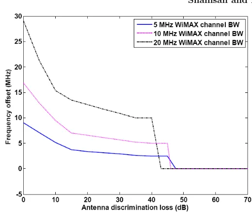
Figure 10. Effect of antenna discrimination loss on spectrum efficiency when interference from WiMAX into fixed service in case of 6×6 kms network cell size.
5 MHz, 10 MHz and 20 MHz WiMAX channel bandwidth, respectively. Moreover, for coexistence the two services by frequency offset equals to the same WiMAX channel bandwidth, it is needed to 10 dB, 9 dB, and 6 dB antenna discrimination loss for 5 MHz, 10 MHz, and 20 MHz respectively. These results indicate that achieving the same intersystem interference scenario by high channel bandwidth requires lower antenna discrimination loss than that in case of low channel bandwidth. This is due to high channel bandwidth is technically having high thermal noise floor which increases the margin between interference and noise floor and thus the required antenna discrimination loss becomes low.
6.2. Antenna Discrimination When WiMAX is the Victim Service
Figure 11. Effect of antenna discrimination loss on spectrum efficiency when interference from fixed into WiMAX service in case of 6×6 kms network cell size.
is shown that for intersystem interference coordination, 3.5 MHz (half of the fixed service frequency bandwidth) is the minimum frequency offset from the carrier frequency in order to initiate the operation of WiMAX and FWA simultaneously. This frequency offset is applicable for all WiMAX channel bandwidths because it depends on the assigned channel bandwidth of interferer spectral mask which here has a value of 7 MHz. Adjacent channel coexistence sharing requires antenna discrimination loss of 35 dB, 34.5 dB, and 29 dB in case of interference to 5 MHz, 10 MHz, and 20 MHz, respectively. Moreover, frequency sharing by co-channel may be valid for antenna discrimination loss of 40.58 dB, 39.03 dB, and 36.03 dB when channel bandwidth of WiMAX is 5 MHz, 10 MHz, and 20 MHz, in that order.
7. CONCLUSION
spectral emission mask in a 6 × 6 kms cellular network cell size. Average interference to noise ratio have been used with different channel bandwidths, and network cell sizes for estimating impact of intersystem interference between WiMAX and fixed service. Antenna discrimination loss have to be adjusted by modifying the off axis angles between WiMAX and fixed services to provide at least 47.58 dB, 46.03 dB, and 43.02 dB to achieve co-channel compatibility for WiMAX channel bandwidth of 5 MHz, 10 MHz, and 20 MHz, respectively. High spectral efficiency in intersystem interference situations could be satisfied by maintaining a significant antenna discrimination loss value.
APPENDIX A.
((C/N)−(C/N+I))[dB] = 1 dB
C/N
C/N +I = 1.26 (as a ratio) (N+I)
N = 1.26
I/N = 0.26
I/N[dB] = −6 dB
REFERENCES
1. Bose, R., “Improving capacity in LMDS networks using trellis coded modulation,”EURASIP J. Wireless Commun. Networking, No. 2, 365–373, Nov. 2004.
2. Salgado, H., “Spectrum allocation for fixed wireless access technologies in the americas,” Proceeding of IEEE Vehicular Technology Conference (VTC’98), 282–287, 1998.
3. Shamsan, Z. A. and T. A. Rahman, “Spectrum sharing studies of IMT-advanced and FWA services under different clutter loss and channel bandwidths effects,” Progress In Electromagnetics Research, PIER 87, 331–344, 2008.
4. Shamsan, Z. A. and T. A. Rahman, “On the comparison of intersystem interference scenarios between IMT-Advanced and fixed services over various deployment areas at 3500 MHz,”
Progress In Electromagnetics ResearchC, Vol. 5, 169–185, 2008. 5. Panagopoulos, A. D., “Uplink co-channel and co-polar interference
6. Mandeep, J. S. and J. E. Allnutt, “Rain attenuation predictions at Ku-band in south east Asia countries,” Progress In Electromagnetics Research, PIER 76, 65–74, 2007.
7. Bose, R., G. Bauer, and R. Jacoby, “Two-dimensional line of sight interference analysis of LMDS networks for the downlink and uplink,”IEEE Trans. Antennas Propag., Vol. 52, No. 9, 2464– 2473, Sept. 2004.
8. Panagopoulos, A. D., P.-D. M. Arapoglou, J. D. Kanellopoulos, and P. G. Cottis, “Intercell radio interference studies in broadband wireless access networks,” IEEE Transactions on Vehicular Technology, Vol. 56, 3–12, Jan. 2007.
9. Arapoglou, P.-D. M., A. D. Panagopoulos, J. D. Kanellopoulos, and P. G. Cottis, “Intercell radio interference studies in CDMA-based LMDS networks,” IEEE Trans. Antennas Propag., Vol. 53, No. 8, 2471–2479, Aug. 2005.
10. Espias, M. and J. Perez, “The viability of fixed wireless access in the Spanish market,”Information Economics and Policy, Vol. 17, No. 1, 85–96, Elsevier, Jan. 2005.
11. Sinka, C. and J. Bito, “Site diversity against rain fading in LMDS systems,” IEEE Microwave and Wireless Components Letters, Vol. 13, No. 8, 317–319, Aug. 2003.
12. Shamsan, Z. A., M. I. Abo-zeed, and J. Din, “Rain fading mitigation in BWA using site diversity,” Proceedings of IEEE Conference (APACE 2007), 1–5, Dec. 2007.
13. Draft Report for ITU-R M.2045, “Mitigating techniques to address coexistence between IMT-2000 Time division duplex and frequency division duplex radio interface technologies within the frequency range 2500–2690 MHz operating in adjacent bands and in the same geographical area,” 2004.
14. Ofcom, “Digital dividend–mobile voice and data (IMT) issues,” Mason Communications Ltd., 2007.
15. ITU-R M. 2113, “Draft new report on sharing studies in the 2500– 2690 MHz band between IMT-2000 and fixed broadband wireless access (BWA) systems including nomadic applications in the same geographical area,” 2007.
16. ETSI EN 301 021 (V1.6.1), “Fixed radio systems; point-tomultipoint equipment; time division multiple access (TDMA); point-to-multipoint digital radio systems in frequency bands in the range 3 GHz to 11 GHz,” 2003.
Available: http://www.ntia.doc.gov/osmhome/reports/ntia05-432/ipc phase 1 report.pdf
18. IEEE Std 802.16.2-2004, “IEEE recommended practice for local and metropolitan area networks coexistence of fixed broadband wireless access systems,” Mar. 2004.