Stability Assessment of Pipeline Cathodic Protection Potentials
under the Influence of AC Interference
Thabane H. Shabangu1, Purva Shrivastava1, *, Bolanle T. Abe1, and Peter A. Olubambi2
Abstract—Metallic pipelines are protected from induced corrosion by the application of coating and Cathodic Protection (CP) systems. The latter is achieved by keeping the pipeline at a constant Direct Current (DC) voltage in relation to the surrounding soil. While this is conventionally meant to arrest corrosion, the Alternating Current (AC) interference from high voltage transmission lines has been a major problem to the CP potential systems of buried steel pipelines. Several research studies dealing with this problem have been published, and a lot of research work is still on going. This work focuses on assessing the stability of the CP potentials under the influence of AC interference. Seven different CP potentials varying from−800 mV to−1200 mV were applied on steel pipe specimen exposed to the AC interference with a varying AC voltage from 0–50 V. The results of the laboratory investigation revealed that CP potential of −1150 mV was more stable under the influence of AC interference, with just a minimal shift from the set value. The results from the corrosion morphology tests on the pipelines using Scanning Electron Microscope (SEM) and Energy Dispersive X-ray Spectroscopy (EDS) reveal the need for optimising the CP potential to provide adequate or optimum protection to the pipelines. Thus, more research studies involving simulation and field studies may lead to a major breakthrough in improving protection potentials.
1. INTRODUCTION
With increasing residential and industrial developments, buried steel pipelines are now widely used to transport water, oil and other fluids for several kilometres to serve the needs of these growing communities. These pipelines are exposed to various environmental conditions such as soil chemistry and air constituents. The integrity of buried steel pipelines has been majorly threatened by soil corrosiveness for decades [1].
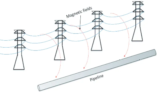
Metallic pipelines are usually made to share corridors for long distances with high voltage transmission lines due to the land use regulations and some environmental factors [2]. The high voltage (HV) transmission lines installed parallel to the pipelines cause AC interference on the pipe due to the time varying electromagnetic field produced by the line current. As a result of the impressed AC potential on the pipeline, the cathodic protection system of the pipe is compromised. The AC interference could be due to the inductive, capacitive and resistive couplings [2–7]. For buried metallic pipelines, the effect of capacitive coupling is negligible due to screening effect of the earth against electric fields. Resistive coupling only occurs when lightning strikes the power line, or when there are faults on the transmission line. The main coupling problem for buried pipelines is the inductive coupling where a fraction of the current flowing through the transmission line conductors is impressed on the metallic pipelines as illustrated in Fig. 1. Consequently, a voltage is induced on the metallic pipeline having its own internal resistance. In extreme cases, for instance during fault conditions where large potential of
Received 27 November 2017, Accepted 6 March 2018, Scheduled 18 March 2018 * Corresponding author: Purva Shrivastava ([email protected]).
1 Department of Electrical Engineering, Tshwane University of Technology, Pretoria, South Africa. 2 Department of Chemical
20 Shabangu et al.
Figure 1. Inductive coupling between high voltage power line and a buried metallic pipeline.
several kilovolts is impressed on the pipeline, the materials of the pipeline can be compromised [8]. The safety of utility workers operating on the pipeline can also be threatened [9, 10].
Several AC mitigation systems have been proposed to control the effect of the AC potential on pipelines [11–16]. In addition to the AC mitigation systems, buried pipelines are usually protected from corrosion through the application of coating and cathodic protection systems [17, 18]. The former requires the surface of the metallic pipelines to be coated with modern and common external coating materials such as fusion bond epoxy, 3 layer polyolefin or polyurethane [19]. The latter is meant to protect the pipeline against corrosion by keeping the pipeline at a constant potential with respect to the surrounding soil. Several CP potentials have been proposed in numerous research studies [1, 20] and technical standards [21, 22]; however, the presence of AC interference from the line shifts the CP potentials. Therefore, the effectiveness of the potentials in protecting the pipelines against corrosion is compromised. In this paper, the assessment of the stability nature of various CP potentials is investigated in the presence of AC potential variations. This paper is organized as follows: Section 2 presents the nature of the problem and an overview of CP systems; Section 3 describes the laboratory setup used for the investigation; Section 4 discusses the results of the laboratory investigation and Section 5 presents the conclusion and future research works.
2. CATHODIC PROTECTION SYSTEMS FOR PIPELINES
Cathodic protection systems are used to control the corrosion of a metal surface, achieved by making the CP system the cathode of an electrochemical cell. CP can be applied by the use of a Sacrificial Anode Cathodic Protection (SACP) system and Impressed Current Cathodic Protection (ICCP) system. The SACP system, shown in Fig. 2 is applied in such a manner that a less noble material acting as a sacrificial anode is connected by metallic conductors to the structure to be protected. Usually materials that are high in electrochemical series, such as magnesium, aluminum and zinc, are used for this purpose. Generally, SACP is used for protection in well coated areas where protective current requirements and soil or water resistivity are relatively low. It is also used where the surface area of a protected structure is relatively small. SACP systems are not suitable for large scale pipelines or in areas where the resistivity is high, as the galvanic anodes cannot produce the required current for adequate protection, so in such cases ICCP systems are preferred.
Figure 2. Sacrificial anode cathodic protection on a buried metallic pipeline.
Figure 3. Impressed current cathodic protection on a buried metallic pipeline.
soil. The ICCP systems are generally high maintenance, and the cost for the initial construction is also high. However, such systems can offer current outputs up to 10000 times more than galvanic anodes.
22 Shabangu et al.
3. EXPERIMENTAL SET-UP
In this section, an experimental investigation conducted on the stability nature of some CP potentials applied to a steel pipe specimen under the influence of AC interference is presented. The applied CP potentials ranges from −850 mV to −1200 mV (with a step increase of 50 mV). The same experimental framework used in [23] is conducted with uniform CP potential ranges to get a more accurate result, and the experiments are conducted for a duration of 7 days at different temperatures and times. Fig. 4 shows a snapshot of the laboratory setup used.
Figure 4. Snapshot of the experimental set up.
As standard practice, the setup consists of a DC source section which acts as a CP system, and the AC source acts as an inductive coupling from the real situation of transmission lines to pipelines. The third category is that of the pipe-soil environment. In this, a simulated soil solution used in [23] is also utilized in the current study. Three steel specimens each with a cross-sectional area of 260 mm2 were separately inserted in a simulated soil solution as shown in Fig. 4. A variable DC source was used to supply varying DC potentials from−850 mV to−1200 mV in range of (−850 mV,−900 mV,−950 mV,
−1000 mV, −1050 mV, −1100 mV, −1150 mV and −1200 mV). The DC power supply used is capable of supplying a voltage range of 0–30 V with a current range of 0–3 A. The applied potential on the steel pipe specimen is done in such a manner that the positive terminal is connected to an anode with its negative terminal to the steel pipe specimen. Thus, the potential of the pipe can be measured directly through a copper-copper sulphate electrode as in Fig. 4. Furthermore, AC is impressed on the steel by the use of a variable power supply with an AC variation capability between 0 and 220 V AC. Since the setup consists of both AC and DC, a 470µF capacitor was used to block DC from flowing through the AC source. On the other hand, a 10 H inductor (impedance for AC current at 50 Hz is 3,150 Ω and 50 Ω for DC current) should sufficiently limit AC from affecting the DC power supply.
Starting with a potential of −0.85 V on the steel pipe by adjusting the DC power supply, the stability in the applied potential of −0.85 V was monitored for a maximum period of 7 days. While no significant variation occurs, that is, the potential is stable, the system is then subjected to AC interference by switching ON the AC power supply adjusted between 0 and 50 V with an increment level of 5 V after every 10 minutes. The corresponding variation in the DC potential of the pipe was monitored and measured with the use of a multi-meter. Previous research work on steady state analysis of the induced potential mostly reveals a voltage range between 0 and 50 V [6, 10, 18, 24–26], thus this range is adopted here. The same procedure was repeated for the other CP potentials of −900 mV,
4. RESULTS AND DISCUSSIONS
The stability of the applied CP potential of −850 mV without the presence of AC interference is shown in Fig. 5. The stability experiment was conducted to check the influence of the soil environment on the applied potential. As maybe observed from Fig. 5, no significant change in the applied potential is noticed. Even while it has been slightly changed during the days 3, 5 and 7, the deviation is negligible enough. However, when an AC potential is applied, a significant variation in the CP potential is observed as shown in Fig. 6, the CP potential of −850 mV, in the presence of AC potential variations. AC potential of 0 V refers to a situation where no AC is interfering with the operation of the CP system, and as this is an ideal scenario, no deviation is observed. However, as the AC potential increases from 0 to 10 V, the CP potential changes drastically as can be seen from the steep slope of the characteristic. Beyond 10 V AC, the rate of change is small and plot nearly flatlines. This means that the applied CP of −850 mV is greatly influenced by lower AC potentials.
In Fig. 7, the effect of AC potential variation on the applied −900 mV on the steel pipe specimen is illustrated. In contrast to Fig. 6 for the−850 mV CP potential, no deviation on the CP potential is
Figure 5. CP potential on steel pipeline without AC interference.
Figure 6. AC interference effect on−850 mV CP potential.
Figure 7. AC interference effect on−900 mV CP potential.
24 Shabangu et al.
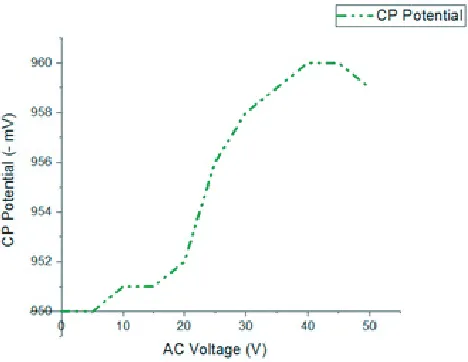
observed for lower values of the AC from 0 to 10 V. However, as the AC voltage increases beyond 10 V, the CP potential changes significantly. In Fig. 7, a larger voltage deviation occurs when the AC voltage varies between 30 V and 35 V. Fig. 8 shows the variation in the applied −950 mV CP potential due to the effect of varying AC potentials. In a similar manner to Fig. 7, no significant changes occur for lower AC potentials from 0 to say 6 V. A larger voltage difference occurs between AC potentials from 20 V to 40 V. Beyond 40 V AC to around 48 V, a stable potential is observed after which it starts diminishing. In Fig. 9, the effect of AC potential on the applied CP of −1000 mV is illustrated. The characteristics are similar to the results presented in Fig. 8. No significant changes occur for lower AC potentials from 0 V to about 6 V. However, for higher AC potential values, the CP potential on the pipe increases almost linearly (with a large voltage difference) and with a little voltage stability between 25 V and 30 V (even though the voltage stability is higher than the supplied true value).
When a CP potential of −1050 mV is applied on the pipe, the effect of AC potential variation interfering with the CP potential is shown in Fig. 10. Also for lower AC potentials, the CP value is stable and not affected by the AC variations. For higher potentials beyond 6 V AC, a different pattern of variation is noticed. In most cases, the CP potential values increase and decrease in a linear manner. Small stability in potential is also observed for AC voltage between 35 V and 45 V. The results obtained
Figure 9. AC interference effect on −1000 mV CP potential.
Figure 10. AC interference effect on −1050 mV CP potential.
Figure 11. AC interference effect on −1100 mV CP potential.
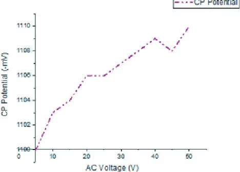
in Fig. 11 are similar to Fig. 10, with the difference that the AC potential values (both lower and higher) have an influence on the applied CP of −1100 mV. A different result is observed when a CP potential of −1150 mV is applied to the steel pipe specimen as shown in Fig. 12, and the potential is stable between voltage ranges of 0 to 15 V and 25 V to 50 V. A significant variation is only observed when AC potential varies from 15 V to 25 V. Between these values, the potential increases and decreases drastically with its peak value at 20 V AC. Fig. 13 concerns with the CP potential variations with AC interference for−1200 mV on the CP. As evidenced in Fig. 13, the potential decreases drastically at all AC voltages higher than 20 V. The deviation from the true potential (that is−1200 mV) is almost linear at some points for example, 0 V to 10 V. The results presented above indicated that the CP potential of
−1150 mV still provided better stability in the presence of AC (with minimal deviation). To this effect, the corrosion morphology at the−1150 mV CP protected steel pipe specimen is assessed.
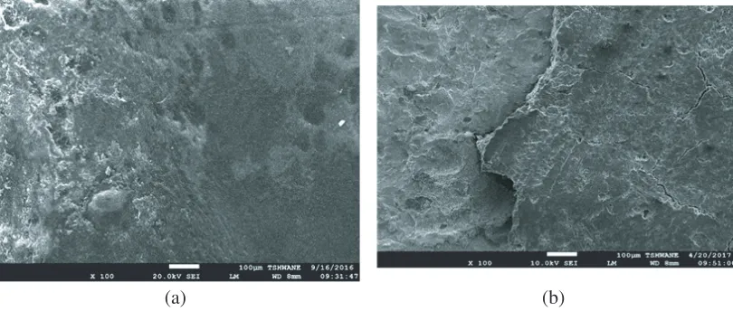
Figures 14 and 15 show the corrosion morphology and elemental analysis of the coated steel pipe specimen before and after AC interference with CP protection−1150 mV.
The results in Fig. 14 are supported by Table 1 showing the elements present in the steel pipe specimen before and after the application of AC interference. Initially, before the presence of AC, the surface morphology shows chain bonding of the elements to be intact without any disintegration.
Figure 13. AC interference effect on−1200 mV CP potential.
(a) (b)
26 Shabangu et al.
(a) (b)
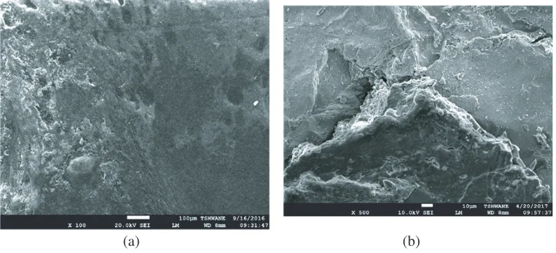
Figure 15. SEM image of the pipe, (a) before AC interference, (b) after AC interference with CP.
However, in the presence of AC, a bonding breakdown is noticed. The percent change that the elements present on the steel pipe specimen before and after AC is also shown in Table 1. In Fig. 15, supported by Table 2, the surface corrosion morphology and the elemental analysis on the coated steel pipe specimen are illustrated. The figure shows that before the specimens are exposed to the AC interference, an insignificant presence of Iron (Fe) is noticed. However, after the specimen is also exposed to AC interference, a higher percentage of Iron at 79.81% on the wall of the steel pipe is observed. Also, other elements such as carbon, silicon, calcium and titanium are no longer visible on the steel pipe after the presence of AC. The results reveal that steel pipe specimen is still not adequately protected, thus, a more advanced protection system remains a future research.
Table 1. Elemental analysis conducted at a point on the steel pipe specimen before and after exposure to AC interference.
Elements % at point number 1 Before Corrosion After Corrosion
C 75.52 23.65
O 24.26 32.18
Si 0.21 44.17
Table 2. Elemental analysis conducted at another point on the steel pipe specimen before and after exposure to AC interference.
Elements % at point number 2 Before Corrosion After Corrosion
C 71.58
-O 27 20.19
Si 0.24
-Ca 0.18
-Ti 0.51
5. CONCLUSION
The influence of AC interference on the stability nature of some CP potential applied to steel specimens is investigated and discussed. The results show that an increase in AC interference also increases the DC cathodic protection potential on the pipeline which affects its protection capabilities. Higher AC interference voltages cause more deviations on the pipe potential. The experimental results reveal that at some lower AC potentials, the AC has no influence on the CP potentials of −900 mV, −950 mV,
−1000 mV and −1150 mV. At these potentials, the applied CP potential shows no deviation from the supplied true value when being subjected to inference from some lower AC potentials. On the other hand, at some higher AC potentials, CP potential of −1150 mV shows promising results remaining stable (no variation from the true potential) as the AC potential becomes higher. The results of the corrosion morphology tests show that the steel pipe specimen is not completely protected from AC interference. Therefore, an optimum protection has not been fully achieved due to the presence of AC. However, it is evident from the experimental results that a CP potential of −1150 mV may provide a better protection to the pipeline in the presence of AC interference, while still not overprotecting the pipeline. The development of an advanced protection system remains a future research. Future work will focus on using a computer software for simulating field pipeline arrangements and simulating those environments with more tools to manipulate any of the field parameters. The impact of both AC and DC stray currents affecting the same pipeline will also form part of the future work.
REFERENCES
1. Brena, A., L. Lazzari, M. Pedeferri, and M. Ormellese, “Cathodic protection condition in the presence of AC interference,”La Metallurgica Italiana, No. 6, 29–34, 2014.
2. Christoforidis, G. C., D. P. Labridis, and P. S. Dokopoulos, “Inductive interference on pipelines buried in multilayer soil due to magnetic fields from nearby faulted power lines,”IEEE Transactions on Electromagnetic Compatibility, Vol. 47, No. 2, 254–262, 2005.
3. Satsios, K. J., D. P. Labridis, and P. S. Dokopoulos, “The influence of nonhomogeneous earth on the inductive interference caused to telecommunication cables by nearby AC electric traction lines,”
IEEE Transactions on Power Delivery, Vol. 15, No. 3, 1016–1021, 2000.
4. Qi, L., H. Yuan, Y. Wu, and X. Cui, “Calculation of overvoltage on nearby underground metal pipeline due to the lightning strike on UHV AC transmission line tower,” Electric Power Systems Research, Vol. 94, 54–63, 2013.
5. Ponnle, A. A., K. B. Adedeji, B. T. Abe, and A. A. Jimoh, “Planar magnetic field distribution underneath two-circuit linear configured power lines in various phase arrangement,”Proceedings of the 12th IEEE AFRICON Conference, 777–781, Ethiopia, Sep. 14–17, 2015.
6. Ponnle, A. A., K. B. Adedeji, B. T. Abe, and A. A. Jimoh, “Variation in phase shift of multi-circuits HVTLs phase conductor arrangements on the induced voltage on buried pipeline: A theoretical study,”Progress In Electromagnetics Research B, Vol. 69, 75–86, 2016.
7. Ponnle, A. A., K. B. Adedeji, B. T. Abe, and A. A. Jimoh, “Variation in phase shift of phase arrangements on magnetic field underneath overhead double-circuit HVTLs: Field distribution and polarization study,” Progress In Electromagnetics Research M, Vol. 56, 157–167, 2017.
8. Adedeji, K. B., A. A. Ponnle, B. T. Abe, and A. A. Jimoh, “Analysis of the induced voltage on buried pipeline in the vicinity of high AC voltage overhead transmission lines,”Proceedings of the 23rd Southern African Universities Power Engineering Conference, 7–12, Johannesburg, Jan. 28– 30, 2015.
9. Australian/New Zealand Standard, T.M, \ Electric hazards on metallic pipelines,” Standards Australia, 4853, AS/NZS, 2000.
28 Shabangu et al.
11. Southey, R., F. Dawalibi, and W. Vukonich, “Recent advances in the mitigation of AC voltages occurring in pipelines located close to electric transmission lines,” IEEE Transactions on Power Delivery, Vol. 9, No. 2, 1090–1097, 1994.
12. Tachick, H., “AC mitigation using shield wires and solid-state decoupling devices,” Materials Performance, Vol. 40, No. 8, 24–27, 2001.
13. Gregoor, R., A. Pourbaix, and P. Carnentiers, “Detection of AC corrosion,” CEOCOR Congress, Paper No. 2, 1–14, Biarritz, France, Oct. 2–5, 2001.
14. Markovic, D., V. Smith, and S. Perera, “Evaluation of gradient control wire and insulating joints as methods of mitigating induced voltages in gas pipelines,”Proceedings of the Australasian Universities Power Engineering Conference, 2001–2006, Hobart, Australia, Sep. 2005, 2005. 15. Shwehdi, M. and B. Al-qahtani, “Cost effective mitigation study of electromagnetic interference by
power lines on neighbouring gas pipeline,”CIGRE C4 Colloquium on Lightning and Power System, 11–17, Kuala Lumpur, May 16–19, 2010.
16. Adedeji, K. B., B. T. Abe, Y. Hamam, A. M. Abu-Mahfouz, T. H. Shabangu, and A. A. Jimoh, “Pipeline grounding condition: A control of pipe-to-soil potential for ac interference induced corrosion reduction,” Proceedings of the 25th Southern African Universities Power Engineering Conference, 577–582, Stellenbosch, South Africa, Jan. 30–Feb. 1, 2017.
17. Ouadah, M., O. Touhami, and R. Ibtiouen, “Diagnosis of the AC current densities effect on the cathodic protection performance of the steel ×70 for a buried pipeline due to electromagnetic interference caused by HVPTL,”Progress In Electromagnetics Research M, Vol. 45, 163–171, 2016. 18. Ouadah, M., O. Touhami, and R. Ibtiouen, “Diagnosis of AC corrosion on the buried pipeline due
to the high voltage power line,”Journal of Electrical Engineering, Vol. 16, 76–83, 2016.
19. Beavers, J. A. and N. G. Thompson, “External corrosion of oil and natural gas pipelines,” ASM Handbook on Corrosion: Environments and Industries, Vol. 13C, 1016–1025, 2006.
20. Xu, L., X. Su, and Y. Cheng, “Effect of alternating current on cathodic protection on pipelines,”
Corrosion Science, Vol. 66, 263–268, 2013.
21. CEN/TS12954, “Cathodic protection of buried or immersed metallic structures: general principles and application for pipelines,” European Technical Specification, Germany, 2001.
22. CEN/TS15280, “Evaluation of AC corrosion likelihood of buried pipelines-application to cathodically protected pipelines,”Technical Specification, European Committee for Standardization, Germany, 2006.
23. Shabangu, T. H., K. B. Adedeji, B. T. Abe, and P. A. Olubambi, “A study on the impact of ac interference on the cathodic protection potentials of buried pipelines,” 25th Southern African Universities Power Engineering Conference, Stellenbosch, South Africa, Jan. 30–Feb. 1, 2017. 24. Isogai, H., A. Ametani, and Y. Hosokawa, “An investigation of induced voltages to an underground
gas pipeline from an overhead transmission line,” IEEJ Transactions on Power and Energy, Vol. 126, 43–50, 2006.
25. Isogai, H., A. Ametani, and Y. Hosokawa, “An investigation of induced voltages to an underground gas pipeline from an overhead transmission line,” Electrical Engineering in Japan, Vol. 164, No. 1, 43–51, 2008.