GSVD-Based Optimal Filtering with Analog Circuits Preprocessing
for Interference Suppression in ELF Communication
Chun-Teng Li1, Yu-Zhong Jiang1, *, Fang-Jun Liu2, and Ting-Ting Jiang3
Abstract—In order to effectively improve the communication quality in the extremely-low frequency (ELF) communication, an integrated model of the analog circuit combined with the multi-channel array algorithm is constructed, and a highly sensitive magnetic sensor is designed. An array algorithm based on generalized singular value decomposition is proposed to find the optimal filter coefficient, and then to achieve the purpose of suppressing interference in ELF communication. In the manufacture of magnetic antenna, the method of partitioned windings divided by acrylic effectively reduces the distributed capacitance of the magnetic antenna, and the rational design of the amplification filter circuit lays the foundation for the interference suppression in the next step. Specific process of the proposed algorithm is deduced. The corresponding evaluation indices are given, and the correlation among evaluation indices is expounded. The simulated and experimental results are discussed respectively. The experimental setups are designed and presented. The results show that no matter which the simulated signal or the experimental data is, the proposed algorithm can effectively suppress the interference, and the output signal to interference ratio is increased by 30 dB.
1. INTRODUCTION
ELF communication [1] is regarded as a kind of reliable and strategic communication mode due to its small attenuation in seawater. However, signals received by ELF communication systems are usually weak, not only in small amplitudes, but also inundated by noise and interference, which makes signal detection rather difficult. In order to improve the communication quality, it is necessary to design a high sensitivity magnetic sensor and use a reasonable algorithm to suppress noise and interference.
In the design of magnetic sensors, Lukoschus [2] proposed the optimization theory of inductive magnetic sensors; Grosz and Paperno [3] designed magnetic sensors with the minimum noise by optimizing the diameter of core and winding diameter; Jilin University studied the main source of noise [4] through the theoretical analysis of coil structure and the preamplifier circuit of the magnetic sensor without magnetic core; Chinese Academy of Sciences reduced the noise influence on the sensor sensitivity [5] based on inductive magnetic sensor with flux negative feedback structure, through the use of flux negative feedback technology and chopper-stabilized amplifier. Aiming at the noise problem of the magnetic sensor in the low-frequency range, this paper chooses the AD797 with low noise as the chip of the amplification module and designs the amplifying and filtering circuit reasonably. In the process of manufacturing the magnetic antenna, the way of piece-wise winding by acrylic clapboard reduced the distributed capacitance of the magnetic antenna effectively.
In aspect of interference suppression algorithms, the traditional algorithms include channel estimation [6], empirical mode decomposition [7], matched filtering [8], etc. The proposed algorithm
Received 23 March 2018, Accepted 29 April 2018, Scheduled 12 June 2018 * Corresponding author: Yu-Zhong Jiang ([email protected]).
1College of Electronic Engineering, Naval University of Engineering, Wuhan 430033, China. 2Academy of Mathematics and Computer
belongs to beamforming algorithm [9]. And the purpose of this kind of algorithm is to design a spatio-temporal filter. The most basic model is a fixed beamforming algorithm, on the basis of which different beamformers were developed according to different cost functions such as minimum mean square error(MMSE) [10] and minimum variance distortionless response [11]. The purpose for adopting the multi-channel array algorithm in this paper is to minimize the signal distortion while suppressing interference using spatio-temporal information, which cannot be achieved by the single-channel algorithm. At present, there are few studies on interference suppression used GSVD method [12] in ELF communication. Besides, the paper introduces the Lagrange factor to control the degree of interference suppression reasonably so as to meet the different requirement of ELF communication.
The structure of this paper is as follows. Section 2 gives the material and methods, designs the magnetic antenna and the amplifying and filtering circuit respectively, describes specific derivation process of the proposed algorithm and evaluation index, furthermore, and reveals the inherent relationship among the different evaluation indexes. Section 3 gives the model of data acquisition in laboratory environment, displays the simulated and experimental results respectively, and analyses the influence of parameters on the algorithm. Section 4 draws the conclusion and summarizes the paper.
2. MATERIAL AND METHODS
The overall model of ELF communication is shown in Fig. 1. Because the ELF signal is weak, and the received signal is mixed with strong 50 Hz and its harmonic interference, the way called analog signal processing is adopted in the front end of receiver to ensure that the desired signal is effectively amplified, including preamplifier, notch filters, low-pass and high-pass filters. After the analog signal processing is completed, the analog signal is converted into the digital signal by the data acquisition device NI 9184, and the desired signal is obtained by using multi-channel array algorithm based on generalized singular value decomposition (GSVD) to suppress the interference. After the desired signal is synchronously demodulated and decoded, finally, the transmitted message is recovered.
Figure 1. The model diagram of ELF.
2.1. Magnetic Antennas
resistance, inductance and capacitance of the magnetic antenna determine the input noise of the amplifier and the measurement accuracy of the magnetic sensor. Therefore, on the basis of satisfying the corresponding bandwidth requirements, the overall optimization of the parameters of the magnetic antenna method is proposed to make the sensitivity as small as possible and to ensure that the weight and volume of magnetic sensor are not too large and convenient to carry.
Given that the magnetic core has greater impact on the performance of the magnetic antenna, the iron-based nanocrystalline alloy with maximum permeability greater than 80000 is chosen as the magnetic core. In the process of magnetic antenna production, the method of automatic winding by motor instead of the manual winding is used, and the motor counter is installed on the motor to record the number of winding turns automatically, which effectively improves the winding efficiency and the accuracy of the number of turns recorded. Furthermore, in order to reduce the distributed capacitance of the magnetic antenna, the method of partitioned windings divided by acrylic clapboard is adopted, the size of the acrylic clapboard designed reasonably, and a hole reserved at the upper right corner of the acrylic clapboard so as to fix the winding end and the winding head at the same piece of acrylic clapboard. By measuring the self-resonant frequency of the antenna, it is found that this winding method can reduce the distributed capacitance of the antenna by an order of magnitude compared with the original unwrapped direct winding method. In order to make the wound coil tightly fixed on the magnetic core, the produced antenna is immersed in the varnish for a period of time. Finally, the parameters of produced magnetic antenna are listed as follows. The number of turns is 20000, the diameter of windings 0.0008 m, and the resistance and inductance are respectively 1.89 KΩ and 163 H.
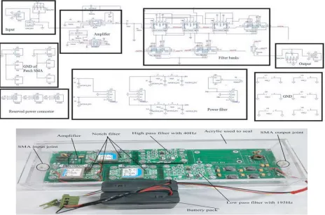
2.2. Amplifying and Filtering Circuits
The role of the preamplifier circuit is to amplify the front-end weak signal and to ensure that the quantization noise does not affect the performance of the receiver. The key to its design is to reduce the noise voltage while taking into account the noise sources of various devices and the 1/f noise of the devices. By referring to instructions and simulating the noise model of the AD797 chip as the amplifier circuit, it is found that the input and output noise of the AD797 is rather low below 1 kHz frequency, which is a better illustration of the extremely low noise nature of the AD797 chip and is well suited as a preamplifier. Therefore, the paper uses AD797 chip to design the preamplifier circuit. When debugging the circuit, the gain of the amplifying circuit should be set reasonably so as to avoid self-excitation of the circuit due to large gain.
Low-pass and high-pass filter circuits are mainly used to filter out out-of-band interferences. In order to make the filter circuits low noise, the active filter is used instead of switched capacitor filter. Compared with a passive filter, the active filter designed in this paper can realize any response without the use of inductors and avoid the thorny problem of magnetic exposure. Secondly, the introduction of an amplifier can make the signal amplified and have no energy loss in the passband, and the load effect is not obvious. In addition, the mutual influence is small when multiple stages are connected, and the high-order filter can be easily realized by using the method of cascade. Furthermore, in aspect of the construction, the universal standard device can be easily assembled, and the module is small in size and light in weight.
Due to a large number of 50 Hz and its harmonic interferences in the laboratory environment, it is necessary to design a notch filter to filter them. Notch filter means that the input signal can be quickly attenuated at certain frequency. Given that the 50 Hz and its odd harmonic component in atmospheric noise is much larger than even harmonics component, this paper uses 50 Hz and 150 Hz notch filters. The notch depth can reach 40 dB in theory, and it can be adjusted by the potentiometer provided by the module. The power supply adopts battery packs. The attenuation of the notch filter was found only 20 dB in the atmospheric environment, which may be due to the offset of the center frequency caused by the change of the input voltage. Therefore, in order to achieve better suppression effect on 50 Hz and its odd harmonic components, two 50 Hz and two 150 Hz notch filters are cascaded in this paper.
Figure 2. The schematic and physical structure of designed amplifying and filtering circuit.
2.3. Signal Model
ConsiderN magnetic antennas, where each signalyn(k),n= 0,1, . . . , N −1, at time k, consists of the desired signal xn(k) and the interference vn(k) composed of jam signal jn(k) and Gaussian white noise
vn(k), which can be expressed as
yn(k) =xn(k) +vn(k) (1)
Consider that the filter wn(k) = [wn0(k), wn1(k), . . . , wLn−1(k)]T has length L and constructs the L -dimension receive vectors yn(k) = [yn(k), yn(k− 1), . . . , yn(k −L + 1)]T, the operator T refers to matrix transposition. Consider that the stacked filter w(k) = [wT0(k), w1T(k), . . . , wTN−1(k)]T has length M (with M = L·N), and the M-dimensional stacked receive vector is defined as yn(k) = [yn(k), yn(k−1), . . . , yn(k−L+ 1)]T. Such that the filtered signal ˆx(k) can be written as
ˆ
x(k) =
N−1
n=0
wnT(k)yn(k) =wT(k)y(k) (2)
where ˆx(k) is an optimal estimate for desired signal x(k). Therefore, the problem of interference suppression is converted into solving the optimal filter coefficient.
Without loss of generality, consider theith channel signal as desired signal, change Equation (2) into vector expression asxˆ(k) =WTy(k), wherexˆ(k) isL×1 vector. The stacked filter matrix is defined as W = [W0, W1, . . . , WN−1]T with M ×L dimension. Wi(0 ≤ i≤ N −1) represents filter matrix of
each channel, and the estimation errore(k) after filtering is defined as
e(k) = xˆ(k)−xi−1(k) =WTy(k)−xi−1(k)
= WT(x(k) +v(k))−xi−1(k) = (WT −UT)x(k) ex(k)
+WTv(k)
ev(k)
whereU = [0L×L,0L×L, . . . , IL×L
i
, . . . ,0L×L]T represents filter matrix with M×L dimension,ex(k) the
signal distortion, and ev(k) the residual interference.
2.4. Evaluation Index
In order to quantify the effect of interference suppression and signal distortion degree, several useful performance evaluation indices are introduced. The most intuitive and simplest method is signal-to-interference ratio (SIR). Since our desired signal is the ith channel, the input SIR is defined as
SIR= σ
2 xi−1
σ2 v
i−1
= E
xT
i−1(k)xi−1(k)
EvT
i−1(k)vi−1(k)
= tr E
UTx(k)xT(k)U
tr{E[UTv(k)vT(k)U]} (4)
where the operator E{·} represents the mathematical expectation, andtr{·} represents the trace of a matrix. In order to evaluate the degree in which the filtering matrix W improves the SIR rationally, the output SIR is defined as
SIR(W) = tr E
WTx(k)xT(k)W
tr{E[WTv(k)vT(k)W]} (5)
In order to determine how much noise is actually attenuated, the interference-reduction factor is defined as
αv(W) = E
vT
i−1(k)vi−1(k)
EeT
v(k)ev(k) =
tr EUTv(k)vT(k)U
tr{E[WTv(k)vT(k)W]} (6) From Equation (6), the factor should be lower bounded by 1. The larger is the value of the factor, the more is the interference reduction.
Generally speaking, interference reduction is done at the expense of signal distortion. Similar to the former interference-reduction factor, signal distortion factor is defined as
βx(W) = E
xT
i−1(k)xi−1(k)
E[(WTx(k))TWTx(k)] =
tr EUTx(k)xT(k)U
tr{E[WTx(k)xT(k)W]} (7) From Equation (7), the larger is the factor, the more is the signal distortion.
In ELF communication, SIR is usually adopted as performance evaluation index of the proposed algorithm. In order to make sure that output SIR is improved, the equation SIR(W)> SIR must be met. Therefore, considering expressions (4), (5), (6) and (7),
SIR(W)
SIR =
αv(W)
βx(W) (8)
Hence, SIR(W)> SIR is met, if and only if αv(W) > βx(W). Therefore, the algorithm is converted
into find an optimal filter to meet αv(W) > βx(W). It means that interference can be suppressed
without signal distortion basically. At this time, αv(W) > 1, βx(W) ≈ 1. So, SIR(W) > SIR is
met. It is why the paper adopts multi-channel array algorithm, which makes full use of spatio-temporal information to improve the communication quality.
2.5. The GSVD-Based Optimal Filtering
The MMSE criterion is adopted, and the cost function is defined as
JMSE(W) =E
e(k)22
=E yT(k)W WTy(k)−2E yT(k)Wxi−1(k)
+E xTi−1(k)xi−1(k)
(9) The optimal filter is designed by setting the derivative to zero, which means ∂JMSE(W)/∂W = 0; therefore, the optimal filter matrix is defined as
whereRyy(k) =E{y(k)yT(k)}is the correlation matrix of the received signal withM×M dimensions, and Ryxi−1(k) =E{y(k)xTi−1(k)} is the cross-correlation matrix of the received signal and the desired signal withM×M dimensions. Given that the desired signal cannot be observed, the received signal and interference are statistically independent, which meansE{x(k)vT(k)}= 0. Therefore, Equation (10) is converted into
W =R−yy1(k)(Ryy(k)−Rvv(k))U (11) whereRvv(k) =E{v(k)vT(k)}is the correlation matrix of the interference with M×M dimensions. It can be seen that the filter matrixW is only related toRyy(k) andRvv(k). The former is estimated by the magnetic sensors receiving the desired signal and interference, and the latter is estimated by the magnetic sensors only receiving the interference.
Although the above algorithm minimizes the mean square error, it cannot control the compromise between the number of interference suppression and the degree of signal distortion well. In ELF communication, it is sometimes desirable to suppress the suppression to the minimum and to allow certain signal distortion. And sometimes it is desirable that the signal is completely undistorted and that interference is properly suppressed to some extent. Therefore, it is more practical to design a filter capable of adjusting the interference suppression and the degree of signal distortion, and the above object is achieved by introducing Lagrange factor.
As can be seen from the previous section, the multi-channel array algorithm can improve the output SIR under the condition that the signal is basically undistorted, which means that the equation
Jx(WK) =E{eTx(k)ex(k)}is minimum, and Jv(WK) =E{eTv(k)ev(k)} ≤Kσ2 is met. Given that the proposed algorithm has the ability to suppress the interference, Kσ2 < σv2
1. By introducing Lagrange
factor λ(λ≥0), the algorithm becomes
WK = minJ(WK, λ) J(WK, λ) =Jx(WK) +λ[Jv(WK)−Kσ2] (12)
The optimal filter matrix is deduced as
WK = (Rxx(k) +λRvv(k))−1Rxx(k)U = (Ryy(k) + (λ−1)Rvv(k))−1(Ryy(k)−Rvv(k))U
= IM×M + (λ−1)R−yy1(k)Rvv(k)−1W (13)
It is not easy to determine the optimal valueλ, but Equation (13) gives the corresponding meanings to different values. Ifλ= 1,WK =W, the overall mean square error was the minimum; ifλ= 0,WK =U, the signal was not distorted at all, but no interference is suppressed; ifλ >1, the ability of interference suppression was stronger, but the signal distortion was greater; ifλ <1, the signal distortion was small but the ability of interference suppression was weak.
It can be seen from Equation (13) that if the correlation matrices Ryy and Rvv can be joint
diagonalized,
Ryy(k) =Qdiag(ε2i)QT
Rvv(k) =Qdiag(η2i)QT (14) Therefore, it can be deduced as
WK=Q−Tdiag
ε2 i −ηi2 ε2
i + (λ−1)ηi2
QTU (15)
The paper uses the joint diagonalization of the correlation matrices Ryy and Rvv by GSVD, so constructs the desired signal matrix Y(k) and interference matrix V(k), making them become block-Toeplitz matrix
Y(k) =yT(k−p+ 1);. . .;yT(k−1);yT(k)p×M
V(k) =vT(k−p+ 1);. . .;vT(k−1);vT(k) p×M
(16)
where p is the number of received signals, and p > M. Owing to block-Toeplitz structure of Y(k) and V(k), the correlation matrix Ryy(k) and Rvv(k) can be approximated by YT(k)Y(k)/p and
VT(k)V(k)/p. The GSVD ofY(k) andV(k) is expressed as
Y(k) =UYdiag(ξi)VT
where UY and UV belong to orthogonal matrix, and V belongs to invertible matrix. The correlation matrixRyy(k) andRvv(k) can be deduced by Equation (17), and substituting the formula into Eq. (13),
the optimal filter matrix can be summarized as
WK=V−Tdiag
ξ2 i −δ2i ξ2
i + (λ−1)δ2i
VTU (18)
3. RESULTS AND DISCUSSIONS
3.1. The Simulated Results
As the atmospheric noise contains strong 50 Hz and its harmonic interference, the paper sets a group of 50 Hz and its harmonic components as the interference (the interference contains 50 Hz, 100 Hz, 150 Hz and 250 Hz), and the other strong interference is set to the Minimum Shift Keying (MSK) signal with 138 Hz center frequency, which has 20 Hz bandwidth. The desired signal is set to 130 Hz signal, and the noise is Gaussian white noise. The input SIR between the desired signal and 50 Hz interference is
Figure 3. The simulated results of interference suppression.
Table 1. The simulated results of interference suppression.
Channel name
Before GSVD method After GSVD method SIR
improved (interference)
SIR improved
(50 Hz) signal
peak (dB)
interference peak (dB)
50 Hz peak (dB)
signal peak (dB)
interference peak (dB)
50 Hz peak (dB) Main
antenna 1
−24.91 −19.3 −12.03
−21.1 −31.54 −40.27 16.05 31.04 Main
antenna 2
−24.76 −20.03 −12.89
Reference antenna
1
−36.86 −19.86 −13.34
Reference antenna
2
set to−12 dB, and the SIR between the desired signal and the MSK interference is−5 dB. Four sets of produced magnetic sensors are used, and two sensors receive the mixed signal composed by the desired signal and interferences. The other sensors only receive the interference. The sampling frequency is set to 2 kHz, and the number of data points is 20000. After a large number of simulations, setting Lagrange factor λ as 1.5, the filter length L is 20, and the number of received signal p is 400. In view of the limited space of the paper, the simulated result under this group of parameters is only shown in Fig. 3 and Table 1.
As can be seen from Fig. 3, the proposed algorithm can effectively suppress the interference. In terms of 50 Hz interference, the interference-reduction factor is up to 28 dB, and the output SIR is 19 dB. For the MSK interference, the interference-reduction factor is up to 14 dB, and the output SIR is 12 dB. It can be seen from the simulated results that the noise floor is properly increased by about 12 dB. This is because the Guassian white noise of each sensor is superimposed by the proposed algorithm. However, the proposed algorithm can make the SIR gain up to 31 dB, and the power spectrum of the output desired signal is also above the noise floor. Thus, the proposed algorithm can improve the communication quality significantly under the condition that the desired signal is basically undistorted.
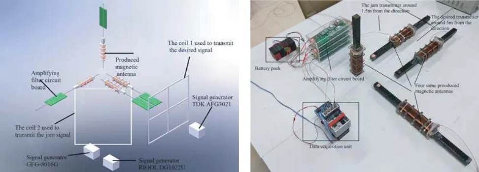
3.2. The Experimental Results
In order to verify that the proposed algorithm is also effective for the experiment in atmospheric environment, a data acquisition platform is set up in the laboratory. The schematic diagram drawn by Solidworks software and the actual acquisition device are shown in Fig. 4. The magnetic sensor is made up with the magnetic antennas and the amplifying and filtering circuit designed in Section 2. The four magnetic antennas are basically the same. Each circuit includes two 50 Hz notch filters, two 150 Hz notch filters, a 40 Hz high-pass filter and a 195 Hz low-pass filter. The signal generator TDK AFG3021 transmits 130 Hz signal as the desired signal to coil 1, which is about 5 meters from the magnetic antennas. The function generator RIGOL DG1022U generates noise to signal generator GFG-8016G which carries on random phase modulation with 138 Hz center frequency as the interference and the bandwidth about 20 Hz. The modulated signal transmits to coil 2, which is about 1.5 meters from the magnetic antennas with 45 degree angle. The physical structure of the above signal generators is shown in Fig. 5. The signal after amplifying and filtering is sent to the data acquisition device NI 9184 whose sampling frequency is set to 2 kHz through the connector SMA to Q9. In order to avoid the introduction of 50 Hz interference, the power supply of data acquisition device and designed circuit board is battery. In order to avoid the mutual influence among magnetic antennas, each board is powered by the separate battery. The experimental results are shown in Fig. 6 and Table 2.
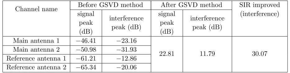
As can be seen from Fig. 6, for the actual atmospheric noise, the designed analog circuit is better to suppress the 50 Hz and its odd harmonic interference, and the proposed algorithm by combining
Figure 5. The physical structure of signal generators (The signal generator in left side generates the desired signal, and the others in right side generate the random phase modulation interference).
Figure 6. The experimental results of interference suppression.
Table 2. The experimental results of interference suppression.
Channel name Before GSVD method After GSVD method SIR improved (interference) signal
peak (dB)
interference peak (dB)
signal peak (dB)
interference peak (dB) Main antenna 1 −46.41 −23.16
22.81 11.79 30.07
Main antenna 2 −50.98 −31.93 Reference antenna 1 −61.21 −12.86 Reference antenna 2 −65.34 −20.06
atmospheric environment changes at any time, coupled with high sensitivity of the designed magnetic sensor, although variety of filter circuits are designed, some radiation signals of switching the door and the lift operation are collected, so the actual power spectrum looks rather messy.
4. CONCLUSION
In this paper, the design of a magnetic sensor and interference suppression algorithm for ELF communication are two important aspects. The steps of design and fabrication of magnetic antenna and amplifying and filtering circuits are given in detail. A multi-channel array algorithm based on GSVD is deduced. Furthermore, the correlation among the corresponding evaluation indices is expounded. Finally, the simulation experiments are carried on analog signal and actual collected data in the laboratory. The simulation result shows that although the algorithm can raise the noise floor to some certain extent, the interference suppression effect is obvious. Moreover, the output SIR gain can reach 30 dB. And the power spectrum of the desired signal is higher than all kinds of interference signals, which can improve the communication quality obviously. It can be seen through the actual collected data that the atmospheric noise still contains higher 50 Hz even harmonic components, and the next step will be continuing to improve the analog circuits.
REFERENCES
1. Ying, W., Y. Jiang, Y. Liu, et al., “A blind detector for Rayleigh flat-fading channels with non-Gaussian interference via the particle learning algorithm,” AEU — International Journal of Electronics and Communications, Vol. 67, No. 12, 1068–1071, Dec. 2013.
2. Lukoschus, D. G., “Optimization theory for induction-coil magnetometers at high frequencies,”
IEEE Trans. Geosci. Electron., Vol. 17, No. 3, 56–63, Jul. 1979.
3. Grosz and E. Paperno, “Analytical optimization of low-frequency search coil magnetometers,”IEEE Sensors J., Vol. 12, No. 8, 2719–2723, Aug. 2012.
4. Shang, X.-L., L. Wang, and J. Lin, “Low noise wideband inductive magnetic sensor,” Journal of Central South University (Science and Technology), Vol. 46, No. 9, 3295–3301, Sep. 2015.
5. Zhu, W., Q. Di, and L. Liu, “Development of search coil magnetometer based on magnetic flux negative feedback structure,”Chinese J. Geophys., Vol. 56, No. 11, 3683–3689, Nov. 2013.
6. Ahmed, M. and L.-N. Tho, “Channel estimation and self-interference cancelation in full-duplex communication systems,” IEEE Transcations on Vehicular Technology, Vol. 66, No. 1, 321–334, Jan. 2017.
7. Zhao, Y., T. Wang, C. Ren, et al., “Research on empirical mode decomposition of signals submerged in a heavy noise,”Journal of Vibration and Shock, Vol. 28, No. 3, 149–151, Mar. 2009.
8. Niu, J. P., T. Su, X. H. He, et al., “Weak NQR signal detection based on generalized matched filter,” Procedia Engineering, No. 7, 377–382, Aug. 2009.
9. Van Veen, B. and K. Buckley, “Beamforming: A versatile approach to spatial filtering,” IEEE ASSP Mag., Vol. 5, No. 2, 4–24, Apr. 1988.
10. Gannot, S., E. Vincent, S. Markovich-Golan, et al., “A consolidated perspective on multimicrophone speech enhancement and source separation,” IEEE/ACM Trans. on Audio, Speech, and Language Processing, Vol. 25, No. 4, 4–24, Apr. 2017.
11. Souden, M., J. Benesty, and S. Affes, “A study of the LCMV and MVDR noise reduction filters,”
IEEE Trans. on Signal Processing, Vol. 58, No. 9,. 4925–4935, Sep. 2010.