Compact Dual-Frequency Microstrip Antenna Array with Increased
Isolation Using Neutralization Lines
Yantao Yu*, Lijun Yi, Xiaoya Liu, and Zhaokai Gu
Abstract—An effective technique utilizing neutralization lines to increase the isolation of a compact two-element dual-frequency microstrip antenna array is proposed in this paper. Two neutralization lines connect the two elements at the edge of each radiating patch. The positions and lengths of the two neutralization lines are studied to get the best performance of element isolation. A prototype of the proposed design was fabricated to validate the results. The measured results agree well with the simulated ones. It is shown that an increase of about 25 dB at the lower frequency and that of 17 dB at the upper frequency in isolation between the two antennas have been achieved.
1. INTRODUCTION
In recent years, the demand for wireless communication keeps rising, such as high data rate and throughput in a given channel with limited bandwidth and to ensure reliable bit error rate. Multiple-input-multiple-output (MIMO) system can achieve these targets admirably. The MIMO technology can improve the communication quality and raise the system capacity by using multiple antennas at the transmitter and receiver terminals [1]. However, if the antennas are implemented in a size-limited platform, there will be challenges in terms of antenna size and mutual coupling between adjacent radiating elements, which affect the overall diversity performance of the MIMO system [2]. Therefore, how to keep the array size compact and at the same time minimize the effects of strong mutual coupling on the performance degradation of the array is a critical issue to address in the multi-antenna communication systems.
The problem of mutual coupling has attracted intensive studies especially in the past decade. Many techniques to reduce the mutual coupling or to increase the port isolation of antenna arrays have been proposed in literatures [3–12]. The element isolation can be increased by properly arranging the antennas in different orientations, for example, an antenna cube [3]. The parasitic elements can be added into the array to create reverse coupling to reduce the mutual coupling among array elements [4, 5]. The decoupling networks [6, 7] can be designed to increase port isolation. Mutual coupling can also be reduced by introducing defected ground structure (DGS) [8, 9], implementing electromagnetic bandgap structures (EBG) [10] or using neutralization lines [11, 12]. Most of the studies presented in literature
reveal a single operating band MIMO antenna system. However, some work shows a dual-band
operation [13–15] for two antennas. Inserting two co-centered circular split ring slots between the two elements of a dual-band printed monopole array was proposed in [13]. Although the structure is very simple, it changes the radiation pattern considerably, especially at the rear side. Paper [14] describes a procedure to achieve simultaneous decoupling and matching at two frequencies using decoupling network with series and parallel combination of inductors and capacitors, but the process of calculation is considerably intricate. Utilizing neutralization lines to reduce mutual coupling of a dual-frequency zeroth-order resonance antennas is presented in [15]. Although the isolation performance is achieved by introducing three neutralization lines, there is a considerably complex structure.
Received 17 August 2015, Accepted 18 September 2015, Scheduled 25 September 2015 * Corresponding author: Yantao Yu ([email protected]).
In this paper, a compact and simple structure is proposed to increase the isolation of a compact two-element microstrip antenna array. Two neutralization lines link the two elements, and each of them corresponds to one of the resonant frequencies of the microstrip antennas. The dimensions of the neutralization lines are optimized to achieve high isolation between array elements. A prototype of the proposed microstrip array has been fabricated and tested. The measured results which agree well with the simulated ones show that the element isolation has been obviously increased at the two operating frequencies.
2. DESIGN OF DUAL-FREQUENCY ANTENNA ARRAY
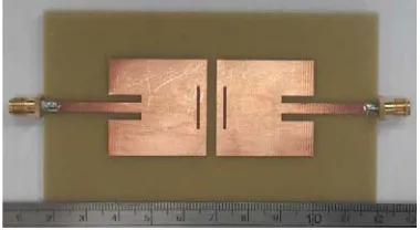
Figure 1 shows the geometry of the proposed array with two neutralization lines. The proposed dual-band antenna array is printed on a 103.2 mm×60 mm×1.6 mm FR4 substrate with relative permittivity of 4.4 and loss tangent of 0.02. A pair of microstrip antennas with the edge-to-edge distance of d= 3.2 mm is used as the array elements. Firstly, a traditional patch antenna with 50 Ω microstrip inset feed was designed. The size of the patch is 30 mm×30 mm, and the resonant frequency is about 2.3 GHz. To obtain another resonance, a rectangular slot was etched on the radiating patch. The antenna was simulated and optimized using Ansoft HFSS, and its design parameters are shown in Table 1.
x y
W W1
2 3
W W
4 W
5 W d
L L
L L1
2 3
4
5 L
L
H
2 1
H
Figure 1. Geometry of the proposed patch antenna array with the neutralization line.
Figure 2. The fabricated dual-frequency microstrip antenna array.
Table 1. Design parameters of the antenna array.
Parameter W L L1 L2 L3 W1 W2 W3 W4 d
Value (mm) 60 103.2 30 10 13.5 30 2.5 1 2 3.2
Figure 2 shows the fabricated dual-frequency microstrip array. The simulated and measured scattering parameters of the array are shown in Figure 3. The measured and simulated results agree well with each other. It can be seen from the measured results that the array resonates at about 2.3 GHz and 4.2 GHz. It is also noted that the coupling coefficient is −14 dB and −11 dB at the two resonant frequencies, respectively. The two neutralization lines connecting the two patch antennas at each side in Figure 1 are used to increase the isolation at the dual operating frequencies.
3. ISOLATION ENHANCEMENT USING NEUTRALIZATION LINES
2.0 2.5 3.0 3.5 4.0 4.5 Frequency (GHz)
0
-10
-20
-30
-40
-50
-60
|
S
| (dB)
Measured S Measured S Simulated S
Simulated S
12
11 12 11
Figure 3. The S-parameters of the designed microstrip antenna array.
2.0 2.5 3.0 3.5 4.0 4.5
Frequency (GHz) -10
-20
-30
-40
-50
S
(dB)
12
L = 29 mm L = 29.6 mm
L = 30.2 mm L = 30.8 mm
5 5 5 5
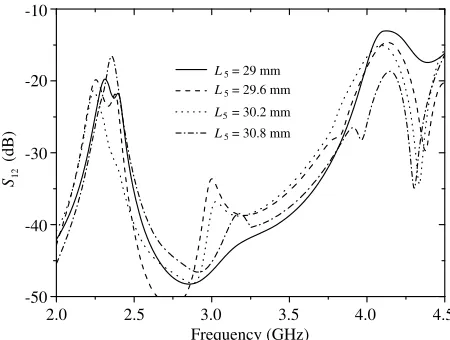
Figure 4. Simulated S12 of the first neutraliza-tion line for different values of L5.
2.0 2.5 3.0 3.5 4.0 4.5
Frequency (GHz) -10
-20
-30
-40
-50
S
(dB)
12
L = 24.6 mm L = 25.2 mm
L = 25.8 mm L = 26.2 mm
4 4 4 4
Figure 5. Simulated S12 of the second neutralization line for different values of L4.
2.0 2.5 3.0 3.5 4.0 4.5
Frequency (GHz) -10
-20
-30
-40
-50
S
(dB)
12
0
W = 0.25 mm W = 0.5 mm W = 0.75 mm
W = 0.1 mm
5 5 5 5
Figure 6. Simulated S12 of the proposed array for different values ofW5.
coupling of the array is discussed in Figure 4 withH2 equal to 4 mm. As shown in Figure 4, the coupling coefficient of the array with the neutralization line changes much more at the upper frequency band than at the lower frequency band with the variation of L5. It is also noted that the frequency shifts downwards at the upper band asL5 increases.
Similarly, the second neutralization line connecting the two elements is added and located at the other side of the array, as shown in Figure 1. WithH1equal to 3 mm, the effect of the variation ofL4on the mutual coupling of the array is shown in Figure 5. It can be seen that asL4 increases the frequency in the lower band also increases. Next, the width of the neutralization lines, W5, is considered, as in Figure 6. It is obvious that the variation ofW5 affects the coupling coefficient at both frequency bands. When W5 = 0.5 mm, significant reduction in mutual coupling can be achieved at both the lower and upper bands.
According to the above study, the dimensions of the neutralization lines can be optimized. With L4 = 26.5 mm andL5 = 31.6 mm, the simulatedS-parameters of the designed antenna array are depicted in Figure 7. As can be seen, the bandwidth of the proposed array almost remains unchanged in spite of a slight frequency shift. However, the coupling coefficient has been reduced to −35 dB at 2.3 GHz and
2.0 2.5 3.0 3.5 4.0 4.5 Frequency (GHz)
0
-10
-20
-30
-40
-50
|
S
| (dB)
S 11without neutralization lines
S without neutralization lines
S with two neutralization lines
S with two neutralization lines 11
12
12
Figure 7. Simulated S-parameters with the two neutralization lines integrated on array structure.
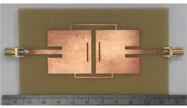
Figure 8. The fabricated dual-frequency microstrip antenna array with neutralization lines.
2.0 2.5 3.0 3.5 4.0 4.5
Frequency (GHz) 0
-10
-20
-30
-40
-50
|
S
| (dB) Measured S
Measured S Simulated S
Simulated S
12 11 12 11
Figure 9. The measured and simulatedS-parameters of the array with neutralization lines.
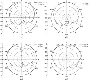
A prototype of the proposed array, as shown in Figure 8, has been fabricated to validate the results. The measured results are illustrated in Figure 9 with comparison of the simulated ones. It can be seen that the measurement agrees well with the simulation, in spite of a slight frequency shift. According to the measured results, an increase of 25 dB at 2.3 GHz and an increase of 17 dB at 4.2 GHz in the element isolation have been achieved, respectively. The simulated normalized radiation patterns of the microstrip antenna array with and without the neutralization lines are shown in Figure 10. It is noted that the patterns keep their general shapes when the neutralization lines are added to the microstrip array.
By assuming uniform external signal source distribution, the envelope correlation coefficient (ECC) between the two antenna ports based on theS-parameters can be calculated by [16]
ρe= |S
∗
11S21+S12∗ S22|2
−1− |S11|2− |S21|2 1− |S22|2− |S12|2
. (1)
0 180 -40 -30 -20 -10 0 -30 -20 -10 0 -40 -30 -20 -10 0 -30 -20 -10 0 -40 -30 -20 -10 0 -30 -20 -10 0 (a) (b) (c) (d) -40 -30 -20 -10 0 -30 -20 -10 0 150 120 30 60 90 330 300 270 240 210 0 180 150 120 30 60 90 330 300 270 240 210 0 180 150 120 30 60 90 330 300 270 240 210 0 180 150 120 30 60 90 330 300 270 240 210 xz-plane
yz-plane xzyz-plane-plane
xz-plane
yz-plane xzyz-plane-plane
Figure 10. The normalized radiation patterns of the array: (a) 2.3 GHz without neutralization lines (NL); (b) 2.3 GHz with NL; (c) 4.2 GHz without NL; (d) 4.2 GHz with NL.
2.0 2.5 3.0 3.5 4.0 4.5
Frequency (GHz) 0.10 0.08 0.06 0.04 0.02 0.00 ECC
without neutralization lines with neutralization lines
Figure 11. The measured envelope correlations of the proposed array.
4. CONCLUSIONS
is achieved at the higher band. Both the simulated and measured results show that the neutralization lines can be used to enhance the element isolation of a compact microstrip antenna array, even for dual frequency bands.
ACKNOWLEDGMENT
This work was supported in parts by the National Natural Science Foundation of China (grant 61101024) and the Fundamental Research Funds for the Central Universities (grants CDJZR12160013 and 106112014CDJZR165504).
REFERENCES
1. Jensen, M. A. and J. W. Wallace, “A review of antennas and propagation for MIMO wireless communication,” IEEE Trans. Antennas Propag., Vol. 52, No. 11, 2810–2824, 2004.
2. Song, L. and J. Shen, Evolved Cellular Network Planning and Optimization for UMTS and LTE, CRC Press, Boca Raton, FL, 2011.
3. Getu, B. and J. Andersen, “The MIMO cube — A compact MIMO antenna,”IEEE Trans. Wireless Comm., Vol. 4, No. 3, 1136–1141, 2005.
4. Farsi, S., et al., “Mutual coupling reduction between planar antennas by using a simple microstrip U-section,” IEEE Antennas and Wireless Propagation Letters, Vol. 11, 1501–1503, 2012.
5. Li, Z., Z. Du, M. Takahashi, K. Saito, and K. Ito, “Reducing mutual coupling of MIMO antennas with parasitic elements for mobile terminals,” IEEE Trans. Antennas Propag., Vol. 60, No. 2, 473–481, 2012.
6. Lee, T.-I. and Y. Wang, “Mode-based information channels in closely coupled dipole pairs,” IEEE Trans. Antennas Propag., Vol. 56, No. 12, 3804–3811, 2008.
7. Yu, Y., Y. Jiang, W. Feng, S. Mbayo, and S. Chen, “Compact multiport array with reduced mutual coupling,”Progress In Electromagnetics Research Letters, Vol. 39, 161–168, 2013.
8. Ou Yang J., F. Yang, and Z. M. Wang, “Reducing mutual coupling of closely spaced microstrip
MIMO antennas for WLAN application,” IEEE Antennas and Wireless Propagation Letters,
Vol. 10, 310–313, 2011.
9. Lin, D.-B., I.-T. Tang, and M.-Z. Hong, “A compact quad-band PIFA by tuning the defected ground structure for mobile phones,” Progress In Electromagnetics Research B, Vol. 24, 173–189, 2010.
10. Veeramani, A., et al., “Compact S-shaped EBG structures for reduction of mutual coupling,” IEEE 2015 Fifth International Conference on Advanced Computing&Communication Technologies (ACCT), 2015.
11. Su, S. W., C. T. Lee, and F. S. Chang, “Printed MIMO-antenna system using neutralization-line technique for wireless USB-dongle applications,” IEEE Trans. Antennas Propag., Vol. 60, No. 2, 456–463, 2012.
12. Cihangir, A., F. Ferrero, G. Jacquemod, et al., “Neutralized coupling elements for MIMO operation in 4G mobile terminals,”IEEE Antennas and Wireless Propagation Letters, Vol. 13, 141–144, 2014. 13. Yu, Y., L. Yi, X. Liu, and Z. Gu, “Dual-frequency two-element antenna array with suppressed
mutual coupling,” International Journal of Antennas and Propagation, Vol. 2015, 2015.
14. Sato, H., Y. Koyanagi, K. Ogawa, and M. Takahashi, “A method of dual-frequency decoupling for two-element MIMO antenna,”PIERS Proceedings, 1853–1857, Stockholm, Aug. 12–15, 2013. 15. Li, L., F. Huo, Z. Jia, and W. Han, “Dual zeroth-order resonance antennas with low mutual
coupling for MIMO communications,” IEEE Antennas and Wireless Propagation Letters, Vol. 12, 1692–1695, 2013.