LHCb High Level Trigger in remote IT datacentre
EdoardoMartelli1,∗,LoïcBrarda2,∗∗,LuisGranado Cardoso2,∗∗∗,MarcCollignon1,∗∗∗∗,Niko Neufeld2,†,TommasoColombo2,‡, andTonyCass1,§
1CERN (Geneva, Switzerland), IT-CS group 2CERN (Geneva, Switzerland), LHCb experiment
Abstract.In 2017 the CERN IT department and the major LHC experiments reviewed the possibility to build a common High Level Trigger facility, to share costs and for a more efficient utilization of computing resources. This paper
describes a Proof-of-Concept built by the CERN IT-CS group and the LHCb online and offline teams to demonstrate the feasibility of the proposal: the
dedi-cated, high speed connection between the LHCb detector and the IT data-centre, the setup of the servers and how they were used for offline simulation and
on-line data taking, the different technologies considered and used, the challenges
encountered and how they were tackled. The Proof of Concept exceed expec-tations and the remote servers were used for real data taking for more than two months during the summer 2018.
1 Introduction
The feasibility of a shared facility for the HLT farms of the four LHC Experiments was reviewed in 2017. The IT department proposed a state of the art data-centre building to be built on the French site of Prévessin, connected with very high bandwidth network links to the four major LHC experiments and to the IT data-centre in Meyrin [1].
The connections of the envisaged shared facility are depicted in figure 1. The main advantages of the proposed solution are:
• the possibility to re-purpose the servers during periods without data taking, and
• a reduction in aggregate costs as infrastructure and operational overheads would be shared between IT and the four experiments.
The main challenges are:
• managing and automating the re-purposing of servers among different management do-mains (IT, LHC experiments), and
• supporting the very high data rates —up to 40 Tbps —from the detectors to the HLTs. ∗e-mail: [email protected] - main author
∗∗e-mail: [email protected] ∗∗∗e-mail: [email protected] ∗∗∗∗e-mail: [email protected]
Figure 1.A proposal for a shared HLT facility.
Unfortunately, construction of such a shared data-centre could not be confirmed early enough to ensure its construction on the timescale necessary to meet the needs of ALICE and LHCb Run3 and these experiments are thus currently constructing dedicated facilities to house their HLT farms near their detectors.
Despite the lack of an immediate need, however, it was considered valuable to perform a proof-of-concept study to inform future discussions about a possible common facility. In fact the remote HLT could be implemented also in the existing data-centre in Building 513.
2 Setup of the case study
The IT-CS group and the LHCb online and offline teams agreed to use their facilities to set up this case study.
The locations involved were:
• the LHCb Experiment at Point 8 in Ferney-Voltaire as the data source, and
• the CERN IT data-centre in Building 513 in Meyrin which hosted the test HLT servers.
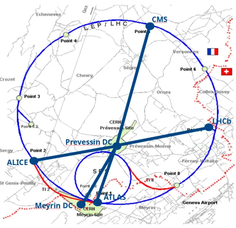
The locations are depicted in figure 2.
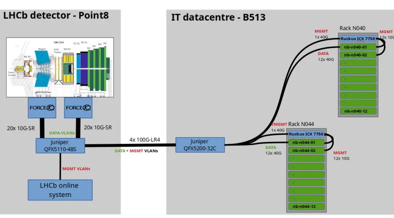
Network connectivity between the two sites was provided by two Juniper QFX switches equipped with four 100 Gbps interfaces each, connected to four fibre pairs.
The switch on the LHCb side was connected to A) the LHCb detector via the production Force10 switch (currently connecting the hardware trigger used for Run1 and Run2); B) to the management network switch. The switch in the IT data-centre was connected to C) two production top-of-rack (ToR) switches for the control/management interfaces of the servers; D) directly to the data interfaces of the test HLT servers.
Figure 1.A proposal for a shared HLT facility.
Unfortunately, construction of such a shared data-centre could not be confirmed early enough to ensure its construction on the timescale necessary to meet the needs of ALICE and LHCb Run3 and these experiments are thus currently constructing dedicated facilities to house their HLT farms near their detectors.
Despite the lack of an immediate need, however, it was considered valuable to perform a proof-of-concept study to inform future discussions about a possible common facility. In fact the remote HLT could be implemented also in the existing data-centre in Building 513.
2 Setup of the case study
The IT-CS group and the LHCb online and offline teams agreed to use their facilities to set up this case study.
The locations involved were:
• the LHCb Experiment at Point 8 in Ferney-Voltaire as the data source, and
• the CERN IT data-centre in Building 513 in Meyrin which hosted the test HLT servers.
The locations are depicted in figure 2.
Network connectivity between the two sites was provided by two Juniper QFX switches equipped with four 100 Gbps interfaces each, connected to four fibre pairs.
The switch on the LHCb side was connected to A) the LHCb detector via the production Force10 switch (currently connecting the hardware trigger used for Run1 and Run2); B) to the management network switch. The switch in the IT data-centre was connected to C) two production top-of-rack (ToR) switches for the control/management interfaces of the servers; D) directly to the data interfaces of the test HLT servers.
The network setup is depicted in figure 3. The list of the equipment used for the case-study is:
Figure 2.Case study locations.
Figure 3.Case study setup
• Network Hardware
• Servers in B513 data-centre:
– 24x servers Supermicro Quanta server with Intel Xeon CPU E5-2630 2.20 GHz, 16GB
of RAM, 1x 10 Gbps NIC for control and 1x 40 Gbps NIC for data traffic.
3 Observed results
3.1 Server automation
The servers in building 513 were originally part of the CERN IT Openstack cloud.
For the hand over to LHCb, the IT ToR switches were reconfigured to be connected at Layer2 to the LHCb Online System, thus routing PXE boot requests from the test HLT servers to LHCb managed DHCP servers, rather than those managed by the IT Department.
This configuration effectively handed control of the machines to LHCb and the Online
System was able to configure the servers as offline Simulation nodes or as HLT nodes ac-cording to the LHC accelerator status, just as for the production HLT servers located at the experiment.
In this proof-of-concept setup, the redirection of the PXE boot packets required some manual cabling and manual reconfiguration of the ToR switches in the Meyrin Data Centre. In a production setup, however, no manual reconfiguration would be required as switching servers between the IT cloud and the Experiment cloud could easily be automated by the IT-CS Network Management System.
3.2 Offline Simulation
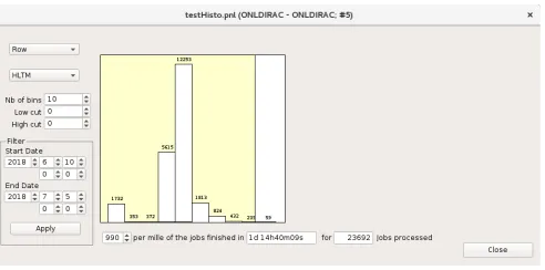
In the first phase of the case study, the nodes were used for offline Monte Carlo simulation. In this period, the 24 nodes in Building 513 (identified as HLTM01 and HLTM02) ran 23692 jobs, 1.5% of the jobs run in the whole LHCb farm in the same period. It was noticed that the jobs in the B513 farm were executed 15% faster than the whole average. Each of the node had 4 CPUs with 10 cores.
These results were confirmed by the values reported in the figures 4 and 5
• Servers in B513 data-centre:
– 24x servers Supermicro Quanta server with Intel Xeon CPU E5-2630 2.20 GHz, 16GB
of RAM, 1x 10 Gbps NIC for control and 1x 40 Gbps NIC for data traffic.
3 Observed results
3.1 Server automation
The servers in building 513 were originally part of the CERN IT Openstack cloud.
For the hand over to LHCb, the IT ToR switches were reconfigured to be connected at Layer2 to the LHCb Online System, thus routing PXE boot requests from the test HLT servers to LHCb managed DHCP servers, rather than those managed by the IT Department.
This configuration effectively handed control of the machines to LHCb and the Online
System was able to configure the servers as offline Simulation nodes or as HLT nodes ac-cording to the LHC accelerator status, just as for the production HLT servers located at the experiment.
In this proof-of-concept setup, the redirection of the PXE boot packets required some manual cabling and manual reconfiguration of the ToR switches in the Meyrin Data Centre. In a production setup, however, no manual reconfiguration would be required as switching servers between the IT cloud and the Experiment cloud could easily be automated by the IT-CS Network Management System.
3.2 Offline Simulation
In the first phase of the case study, the nodes were used for offline Monte Carlo simulation. In this period, the 24 nodes in Building 513 (identified as HLTM01 and HLTM02) ran 23692 jobs, 1.5% of the jobs run in the whole LHCb farm in the same period. It was noticed that the jobs in the B513 farm were executed 15% faster than the whole average. Each of the node had 4 CPUs with 10 cores.
These results were confirmed by the values reported in the figures 4 and 5
Figure 4.Number of jobs and their average duration ran on the HLTM servers during offline simulation.
Figure 5.Number of jobs and their average duration ran on the whole LHCb HLT servers during offline simulation.
3.3 Online Remote High Level Trigger
When the LHC finally started delivering collisions in July 2018, the servers were converted to HLT nodes and added to two sub-farms (HLTM01 and HLTM02) of the production LHCb HLT farm.
The remote nodes behaved correctly and performed exactly as the production nodes. The LHCb online team actually commented: “Operationally and performance-wise, it seems to be the same as running a sub-farm at Point 8".
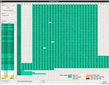
Figure 6 shows input rate of all the nodes used in the LHCb farm. The rates on the remote nodes are similar to those of other nodes.
4 DWDM transmission test
During Run3, LHCb will need to send data to the HLT farm at rates of up to 40 Tbps. While data transmission at such rates is affordable over very short distances, the transmission over distances exceeding a few tens of meters can quickly become very expensive, especially if fibre connections are scarce, as is the case between LHCb Point 8 and the IT data-centre in Building 513.
Given the very few fibre pairs available, two options were costed during the design studies for the proposed shared facility on the Prévessin site: installation of additional fibres and the use of DWDM (Dense Wavelength Division Multiplexing) transmission equipment. At the time of those studies, the only DWDM equipment available was that traditionally used by Telecom operators to cover longer distances and the cost of the DWDM solution exceeded the estimated cost of digging the relatively short trenches (<10km) required for the installation of additional fibres.
Since those studies, however, a more cost effective DWDM solution has appeared based on a new emerging technology, PAM-4 (Pulse Amplitude Modulation with 4 levels of pulse modulation). The Remote HLT proof-of-concept study provided a valuable opportunity to test this technology in a real-world scenario.
The PAM-4 technology could be tested thanks to the collaboration with Smartoptics[2], a Scandinavian manufacturer of transmission equipment, which provided a demo kit.
The significant cost advantages of the PAM-4 technology based DWDM solution is that the QSFP-28 100 Gbps optical transceivers can be plugged directly into standard switches or servers’ NICs. In our case, the transceivers were plugged into the Juniper switches already deployed for the case study.
Unfortunately, though, these transceivers have the peculiarity of having a transmission power level (-11 dBm) lower of its input sensitivity (-2 dBm). For this reason, an active line system is always necessary to amplify the signal. In the Smartoptics solution, the active line system was also the multiplexer/demultiplexer that merges the different signals into a single fibre pair.
4.1 Network setup
Initially it was planned to replace the four fibre pairs providing a 400 Gbps with 100GbaseLR4 optics by a single fibre pair using the PAM4/DWDM system to multiplex the four 100 Gbps streams.
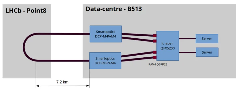
However, the demo kit consisted of only two 100 Gbps DWDM channels, so the band-width had to be reduced to 200 Gbps. Additionally, the Juniper switch at Point 8, a QFX5110,
was not able to supply sufficient power to meet the requirements of the laser of the PAM-4
optics. As a consequence, two fibre pairs were looped together in Point 8 and the test was performed not with real data from the experiment but rather with a simulation of traffic gen-erated by servers in B513. This change to our plans, however, does not affect the utility of the tests for our purposes—and, in any case the two-day period during which the demo kit was available did not correspond with a period of data taking. Figure 7 depicts the configuration of the network setup.
Figure 7.DWDM PAM-4 test setup.
4.2 Findings
The PAM-4 technology proved to be suitable for affordable DWDM transmission over the
link distance tested, around 15 km. In particular, the tests showed that:
• PAM-4 optical transceivers are usable with devices, such as the Juniper QFX5200-32C
which support high power optical modules,
• the PAM-4 transceivers place no special requirements on the operating system; the Juniper
switch used for the tests had a standard Operating System version installed, and.
• the two channels ran with high load for more than 12 hour without any transmission errors.
Some references to Juniper JUNOS commands used in the test are reported in Appendix A.
5 Conclusions
The tests demonstrated that a common computing facility for a shared Software High Level Trigger has been proved feasible. In this case the servers were shared between IT and LHCb, but the setup could be easily extended to other Experiments.
Additionally, we have shown that PAM-4 DWDM technology is an affordable and ready-to-use option to support Terabit data transmission over medium-range distances using a lim-ited number of fibre pairs.
Appendix A: Juniper JUNOS
Version
The PAM-4 QSF28 optical transceiver are supported on Juniper QFX running JUNOS version 17.3 or later [3].
Configuration
set interfaces et-0/0/51 gigether-options fec none set interfaces et-0/0/51 otn-options laser-enable set interfaces et-0/0/51 otn-options is-ma
set interfaces et-0/0/51 otn-options fec none
Show commands
This command shows the recognized PAM-4 transceivers
# run show chassis hardware [...]
QSFP-100GE-DWDM2 QSFP-100GE-DWDM2
This command shows the two 50 Gbps lines up and their power levels
# run show interfaces diagnostics optics et-0/0/31 Physical interface: et-0/0/31
[...] Lane 0
Laser bias current Laser output power Laser receiver power [...]
Lane 1
Laser bias current Laser output power Laser receiver power [...]
: 60.673 mA
: 0.111 mW / -9.56 dBm
: 1.739 mW / 2.40 dBm
: 78.699 mA
: 0.111 mW / -9.55 dBm
: 1.595 mW / 2.03 dBm
References
[1] I.Bird, H.Meinhard,Evolution of CERN facilties(HSF workshop, San Diego (US) - Jan-uary 2017)
https://indico.cern.ch/event/570249/
[2] Smartoptics, Ryensvingen 7 NO-0680 Oslo, Norway
https://www.smartoptics.com/
[3] Juniper Networks, "Junos" Operating System, version 17.3, not publicly available.