DD-
α
AMG on QPACE 3
Peter Georg1,,Daniel Richtmann1,, andTilo Wettig1
1Department of Physics, University of Regensburg, 93040 Regensburg, Germany
Abstract. We describe our experience porting the Regensburg implementation of the DD-αAMG solver from QPACE 2 to QPACE 3. We first review how the code was ported from the first generation Intel Xeon Phi processor (Knights Corner) to its succes-sor (Knights Landing). We then describe the modifications in the communication library necessitated by the switch from InfiniBand to Omni-Path. Finally, we present the perfor-mance of the code on a single processor as well as the scaling on many nodes, where in both cases the speedup factor is close to the theoretical expectations.
1 Introduction
The lattice QCD (LQCD) community has traditionally been an early adopter of new computing and network architectures. This typically requires major efforts porting simulation code or even commu-nication libraries. The Regensburg lattice group (RQCD) has been involved in such efforts, as well as supercomputer development, for more than a decade. While the first computer in the QPACE series [1,2] was based on IBM’s Cell processor and an FPGA-based custom interconnect, the subsequent machines are using Intel’s Xeon Phi series with standard interconnects (see Sec.2.1). To satisfy the increasing demands of the RQCD physics program we use a state-of-the-art method, DD-αAMG [3], to solve the discretized form of the Dirac equation. The high-performance implementation of this solver on QPACE 2 is described in [4–7]. The present contribution focuses on the software efforts we made to efficiently run this implementation on QPACE 3.
This paper is structured as follows. In Sec.2we give an overview of QPACE 3 and highlight the differences to QPACE 2 in terms of processor and network. We discuss the network technology in some detail because it has changed rather drastically. In Sec.3we describe how our solver and our communication library were adapted to the new technologies. In Sec.4we present single-node and multi-node benchmarks of the solver on QPACE 3 and compare the results with numbers obtained on QPACE 2. In Sec.5we conclude and give an outlook on future work.
2 QPACE 3
2.1 Overview
While QPACE 2 [8] is based on the Knights Corner (KNC) version of the Intel Xeon Phi processor series and an FDR InfiniBand network, its successor QPACE 3 utilizes the current Xeon Phi processor,
Knights Landing (KNL), and Intel’s new Omni-Path fabric. QPACE 3 was installed in two phases. Phase 1 consists of 352 nodes, each equipped with a 64-core Xeon Phi 7210 running at a clock frequency of 1.3 GHz. Each core can run up to 4 hardware threads, giving a total of 256 threads per chip. The KNLs have 16 GB on-package high-bandwidth memory, denoted MCDRAM by Intel, as well as 48 GB of DDR4 memory. The Omni-Path network is arranged in a 2:1 blocking-tree topology, where we use edge switches exclusively. This system was ranked 5th in the November 2016 issue of the Green 500 list and 18th in June 2017, both times being the most energy-efficient KNL system on the list. Phase 2 consists of 320 nodes with almost the same configuration. The only differences to Phase 1 are the doubled amount of DDR4 memory (96 GB instead of 48) and the blocking factor of 5:1. Given a fixed budget, these choices were made to be able to efficiently run ensemble-generation jobs that require strong scaling to many nodes on phase 1 as well as weak-scaling analysis jobs that require more memory per node on phase 2. All data shown in these proceedings were obtained on QPACE 3 (or on QPACE 2 when comparisons are made).
2.2 KNC vs. KNL hardware comparison
While the KNL is quite similar to the KNC from the point of view of a software developer, with the exception that the KNL is now self-bootable,1the hardware has been changed quite significantly. Starting at the innermost level, the first improvement is the addition of a second vector processing unit (VPU), which enables a KNL core to issue twice as many floating-point operations per clock. Another improvement is that these cores are now able to execute instructions out of order, which reduces stalling penalties when cache misses occur. Furthermore, a KNC core could issue instructions from a given thread only every other cycle, which led to the need to have at least two threads running on the same core to be able to issue instructions in each cycle. This restriction is no longer present on the KNL. Concerning the cache structure, the per-core size of the L1 and L2 caches stays constant at 32 kB and 512 kB, respectively. However, with the KNL, Intel introduces the concept of a tile, which bundles two cores together sharing 1 MB of L2 cache. In contrast to standard Xeon processors, there is no shared L3 cache. However, Intel makes up for that by adding an on-package high-bandwidth memory (MCDRAM) with a capacity of 16 GB and a bandwidth of about 420GB/s, in addition to a standard DDR4 memory interface with 6 channels and a bandwidth of about 80GB/s(both numbers are for the KNL 7210, to be compared with about 160GB/s for the KNC 7120). The MCDRAM is probably the most significant new feature of the KNL. There are different usage models for it, called memory modes. It can either be used as a large L3 cache (Cache mode), as a directly mapped NUMA node yielding an extra 16 GB of memory in addition to the DDR4 memory (Flat mode), or a combination of both, called Hybrid mode. The tiles, the MCDRAM and DDR4 memory controllers, and the distributed tag directory are connected in a two-dimensional mesh, in contrast to the KNC’s ring bus. According to Intel, this yields higher bandwidth and lower latency between the cores. This feature is by now also incorporated in the Xeon server architecture. The 2D mesh increases the flexibility of configuration options of the KNL even further with so-called cluster modes. It enables the chip to be used either as is (All-to-All) or divided into two/four equal parts which are then either software transparent (Hemisphere/Quadrant) or exposed to the operating system as separate NUMA domains (SNC2/4). From first to last, these modes increase the affinity between tile, distributed tag directory, and memory, thus yielding lower latency and higher bandwidth.
1A PCIe card was also planned but never reached the mass market.
2.3 InfiniBand vs. Omni-Path hardware comparison
QPACE 3 utilizes the Omni-Path interconnect, replacing the previously used InfiniBand, for commu-nication in multi-node jobs and access to the shared network storage. As shown in previous work [7] optimization for a particular network may yield significant improvements compared to relying on plain MPI. Therefore our DD-αAMG implementation uses a custom communication library, pMR. Previously, pMR only supported InfiniBand and local inter-process communication, leveraging Linux CMA. The idea now is to add support for Omni-Path to pMR. To do that properly, it is crucial to un-derstand the hardware, especially the differences to the well-known InfiniBand hardware. Apart from many differences that do not affect us, there are two main differences of these competing technologies we need to take a closer look at: connection-oriented vs. connectionless communication and intercon-nect offloading vs. onloading.
2.3.1 Connection-oriented vs. connectionless communication
Omni-Path implements connectionless communication only, while InfiniBand mainly relies on connection-oriented communication for reliable data transfer. The InfiniBand specification also in-cludes connectionless reliable and unreliable data transfers, but the former is not implemented in any well-known hardware. For simplicity, we ignore unreliable data transfer as it is not used in any communication pattern of interest to us.
Connection-oriented communication requires one connection for each pair of processes that com-municate with each other. Each connection consumes a certain amount of host memory, and the total memory utilization scales linearly with the number of connections. The InfiniBand Host Chan-nel Adapter (HCA) uses on-chip memory to cache connection-related data, but if the cache is full it has to exchange data with the host’s main memory via PCIe, resulting in a performance penalty. It is therefore sensible to minimize the number of connections.
In a connectionless approach it is only necessary to set up communication endpoints and exchange address information with all other peers once (with MPI, typically during the initialization phase). This allows for scaling of applications to an arbitrary number of processes without any noticeable increase in the resources required per process.
The preceding discussion implies that connectionless communication should be superior. For communication patterns that rely heavily on all-to-all communication, this indeed seems to be the case [9]. However, there are two reasons why connection-oriented communication can still obtain similar or better performance.
First, many stencil-type applications, including LQCD, only require a limited subset of commu-nication patterns for performance-relevant parts, in particular nearest-neighbor halo exchanges and global reductions. The former requires a maximum of 2dconnections per process in ad-dimensional theory. The latter is often implemented using the recursive-doubling algorithm, which in turn consists of nearest-neighbor exchanges in a log2(p)-dimensional grid, where p is the number of processes. Hence, it only adds log2(p) connections, some of which might even be identical to the connections already set up for halo exchanges. Assuming a 256-node job with one process per node, no more than 8+log2(256)=16 connections are required to be set up for those two communication patterns. For other non performance-relevant parts, e.g., parallel input/output to the shared network storage, con-nections can be set up dynamically without any noticeable impact on wall-clock time.
Transport Service that enables processes running on the same node to share certain connections [10] and the Dynamically Connected (DC) Transport service that hands over the connection management to the HCA, which then sets up or tears down connections dynamically as required [11]. However, if the number of connections is low, as in stencil-type applications, these new modes are not necessary and the traditional reliable connected (RC) mode still yields best performance.
2.3.2 Interconnect offloading vs. onloading
Interconnect offloading/onloading specifies whether network functions are offloaded to the network adapter (InfiniBand HCA), or onloaded onto the CPU (Omni-Path).
Onloading interconnect technology tends to be less complex and hence easier to build. However, while the CPU is managing and executing network operations it is not available for other tasks, most importantly computations. Whether this CPU overhead is significant depends on the particular appli-cation.
Offloading hardware does not block any compute resources and can be beneficial in two ways. First, if an application is able to overlap communication and computation, the CPU can continue to execute computation tasks while the network adapter performs communication. This is true for LQCD simulations, where many algorithms allow for overlap of computation and halo exchanges. Second, even if no overlap is possible, offloading enables several technologies that can improve per-formance. One example is RDMA, which reduces the latency involved in non-overlapping halo ex-changes. Another example is relevant for the other important communication pattern in LQCD, i.e., global reductions. These can hardly be overlapped with computation, as the result is either required immediately or is used as a stopping criterion in iterative algorithms. Most InfiniBand adapters nowa-days support offloading collective routines to the HCA, reducing the involvement of the host CPU in these operations [12]. For global reductions, this approach is taken even further with the most recent InfiniBand networks, which now support in-network computing and in-network memory to reduce data movement [13].
3 Porting of simulation code and communication library
3.1 DD-αAMG for Xeon Phi
The starting point of the present work is our implementation [5, 6] of the DD-αAMG algorithm for QPACE 2. This implementation contains a number of optimizations with respect to the original Wuppertal code (which was neither threaded nor vectorized). In the following we describe these optimizations, most of which are now part of the official DD-αAMG code base [14]. We adapted the data layout to be able to make efficient use of the hardware (i.e., the caches and the 512 bit vector registers), performed extensive vectorization using compiler intrinsics, and inserted many software prefetching directives to overcome the limitations of the KNC. Furthermore, we implemented an MPI-like threading model with fully persistent threads and further enhanced the use of mixed precision by adding support for storing some data structures in half precision, i.e., 16 bit floating-point numbers.
The subject of this contribution is the porting of our existing code base to QPACE 3. Reference [4], which was prepared in collaboration with Intel engineers and is part of our code base as the fine-grid smoother, states that the port from KNC to KNL will require only modest efforts since the instruction set architecture of these two processors is quite similar. Mainly, we need to replace the explicit IMCI intrinsics scattered all around the code by the corresponding AVX512 intrinsics. We realize this by introducing a lightweight abstraction layer consisting of small functions. This layer wraps the bare
inline void store(half *data, maskF mask, regF ®) {
#if defined (KNC)
_mm512_mask_extstore_ps(data, mask, reg, _MM_DOWNCONV_PS_FLOAT16, 0);
#elif defined (KNL)
_mm256_store_si256( (__m256i *)data,
_mm512_cvtps_ph(
_mm512_mask_blend_ps(
mask,
_mm512_cvtph_ps(_mm256_load_si256((__m256i const *)data)),
reg),
_MM_FROUND_TO_NEAREST_INT));
#endif }
Listing 1.Wrapper function for a masked store operation from a SIMD register to memory in half precision. The KNL code is inspired by the up/down conversion in the code generator of the QPhiX library [15].
intrinsics, which is mostly straightforward except for the permutation intrinsics. At the time of this writing, no further KNL-specific optimizations have been performed.
An issue of particular interest for our porting efforts is the support for half precision. The KNC does not support computations in half precision, but is able to do on-the-fly up/down conversions in hardware when loading/storing data from/to memory. We utilize this feature in our code to reduce the working set size, and as a consequence the requirements on cache capacity and memory bandwidth. However, on the KNL the up/down conversions are no longer part of the instruction set. We attempted to work around this problem by utilizing legacy Intel processor instructions, as depicted in Listing1. Unfortunately, this attempt actually degrades the performance, see the benchmarks below.
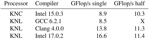
In contrast to the KNC, where only the Intel compiler and its runtime libraries are usable, the KNL is supported by all three major compiler suites: GCC, Clang, and Intel. In Tables1and2we compare the single-core performance of two important code parts, the MR inversion within a domain and the entire Schwarz method, obtained with these compilers.2
Processor Compiler GFlop/s single GFlop/s half
KNC Intel 15.0.3 8.9 10.3
KNL GCC 6.2.1 8.5 X
KNL Clang 4.0.0 13.8 11.3
KNL Intel 17.0.2 16.6 11.4
Table 1.Single-core performance for the MR inversion within a domain.
Processor Compiler GFlop/s single GFlop/s half
KNC Intel 15.0.3 7.4 9.0
KNL GCC 6.2.1 5.6 X
KNL Clang 4.0.0 9.2 7.6
KNL Intel 17.0.2 9.7 7.6
Table 2.Single-core performance for the Schwarz method.
We see that the Intel compiler yields the best performance, closely followed by Clang. On KNL, half precision deteriorates the performance, rather than improving it, in contrast to KNC. This may be a problem with our implementation and will be investigated further in the future.
The KNC has no L1 hardware prefetcher, and the performance of the L2 prefetcher is not optimal. Therefore software prefetching of data to the caches is essential for achieving good performance on KNC. Although the KNL now features an L1 hardware prefetcher, we still use manual software prefetching since our code base already contains these directives.
3.2 pMR communication library
In Sec.2.3we have discussed the hardware differences of InfiniBand and Omni-Path. In this section we take a look at the Omni-Path software stack to identify necessary modifications of our own com-munication library.
There are currently two APIs available to work with Omni-Path. The first API, which MPI im-plementors have been encouraged to rely on, is defined by libfabric, which is a core component of OpenFabrics Interfaces (OFI), a common framework for various interconnects. This API is supposed to be hardware agnostic and yield good performance on any supported hardware. However, this is currently not the case. Although one can, in theory, use the same user code on top of this API on, e.g., InfiniBand and Omni-Path hardware, this leads to severe performance degradation. Therefore, in practice the user code needs to be adapted to the hardware to achieve good performance. The sec-ond API is Performance Scaled Messaging 2 (PSM2), which is used by libfabric under the hood for Omni-Path. Due to the current limitations of libfabric just described, it is sensible to use PSM2 di-rectly to avoid performance degradation due to unsuitable abstraction. This is in fact what many MPI implementations still do, and we also follow this path for pMR.
The PSM2 API supports a tag-matched two-sided messaging model that is very similar to the MPI two-sided messaging API. In contrast to InfiniBand it is not necessary to register any memory region for use as send or receive buffers. Although PSM2 is the lowest-level Omni-Path API, it not only supports Omni-Path but also includes a self (for intra-process communication) and a shared-memory (for local inter-process communication) provider. Furthermore, PSM2 over Omni-Path supports two send methods, programmed input/output (PIO) and Direct Memory Access (DMA), and two receive methods, Token ID (TID, commonly known as rendezvous) and eager. These methods are mainly chosen by globally set thresholds and can hardly be influenced by the user code. The send method has an impact on the CPU utilization. As for the receive methods, the eager protocol might be able to reduce network latency by adding an additional memory copy on the receiving side.
In Fig.1we compare the performance of all available combinations of PSM2 send and receive methods as a function of the KNL memory modes. For all three combinations there are only marginal differences between MCDRAM and DDR4, which presumably are due to the slightly lower latency of DDR4. For PIO/eager and DMA/TID there is no significant dependence on the memory mode, while for DMA/eager the performance of the additional memory copy depends on the memory mode, with cache being worse than flat. Note that this synthetic benchmark is only useful to identify the best memory mode. It cannot identify the best combination of send/receive methods because it neglects the CPU utilization. The global thresholds at which PSM2 switches between different methods should be tuned using benchmarks of the actual application.
Since the PSM2 API is very similar to MPI it is easy to port existing MPI software to run directly on top of PSM2. However, there is a limitation in PSM2 which potentially impacts performance: PSM2 is limited to open only one endpoint per process,3but one endpoint is not sufficient to achieve 3After completion of the work presented here, which is based on Omni-Path Fabric Software 10.3, this limitation has been removed in version 10.5. See Sec.5for future opportunities utilizing the updated software.
0 32 64 96 128
0 50 100 150
Message size in KiB
Time
per
iteration
in
µ
s
PIO/eager Cache DMA/eager Cache DMA/TID Cache
PIO/eager DDR4 DMA/eager DDR4 DMA/TID DDR4
PIO/eager MCDRAM DMA/eager MCDRAM DMA/TID MCDRAM
Figure 1.Ping-ping benchmark of PSM2 send and receive methods as a function of the KNL memory modes, cache and flat. For flat mode the application was bound once to DDR4 and once to MCDRAM. The combination PIO/TID is not available.
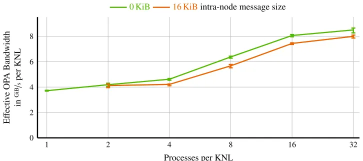
full bandwidth utilization (see Fig.2below). For non-threaded MPI applications this is obviously not an issue since there are many processes, and therefore many endpoints, per node. However, all of our software is based on hybrid MPI+OpenMP [4,5]. To obtain full bandwidth we need to open more than one endpoint, and thus we need more than one process per node. This in turn adds inter-process communication overhead within every node. This intra-node overhead is not negligible but can be reduced by utilizing fully threaded communication.
In Fig. 2 we show the effective Omni-Path bandwidth per KNL depending on the number of processes per KNL. The effective bandwidth increases with the number of processes (=endpoints), and we need at least 16 processes per KNL to get close to peak bandwidth.
1 2 4 8 16 32 0
2 4 6 8
Processes per KNL
E
ff
ecti
ve
OP
A
Bandwidth
in
GiB
/
s
per
KNL
0 KiB 16 KiBintra-node message size
Figure 2. Halo-exchange benchmark running on 16 KNL nodes. Inter-node message size per process was set to 512 KiB/(number of processes per node) to have a constant amount of data per node transferred via
Omni-Path. For the 0 KiB intra-node message size, the processes were synchronized to ensure that all processes are communicating at the same time and not sequentially. The 16 KiB intra-node message size was chosen to simulate real-world applications.
4 Performance figures for DD-
α
AMG
4.1 On-chip strong scaling
We first investigate the on-chip scaling behavior of DD-αAMG, i.e., the scaling of the wall-clock time for a single solve with the number of cores utilized on a single Xeon Phi. Both on KNC and KNL we use the standard hybrid approach with one process per chip and threads on all cores (in our case, 4 threads per core). All results are for a 163×32 lattice, which fits in the 16 GB corresponding to the total memory of a KNC or the MCDRAM of a KNL. Before discussing the results we remind the reader of the relevant peak performance figures. The ratio of the peak floating-point performance of KNL and KNC is 2.2. The memory bandwidth is about 420GB/sfor KNL with MCDRAM, 80GB/sfor KNL with DDR4, and 160GB/sfor KNC, respectively, i.e., the ratio of KNL with MCDRAM to KNC is about 2.6.
Our results are depicted in Fig.3, where all numbers are normalized to the value of a single KNC core. We first notice that on the KNL there is no significant difference between cache mode and flat mode from MCDRAM, and therefore we do not consider cache mode further. The remaining results should be interpreted with care. Note that we are benchmarking a complex code and not just a simple kernel. The DD-αAMG code contains many parts, some of which are memory-bandwidth bound, while others are compute bound. Microbenchmarks have shown that the total memory bandwidth of both KNC and KNL scales roughly with the number of cores utilized. (For KNL with DDR4 this statement only holds for low core count.) Therefore, for both memory-bandwidth and compute bound code, the ideal scaling would be linear in the number of cores. However, once more and more cores are utilized, the overhead for synchronization between threads leads to a flattening of the speedup curve. This is indeed what we observe qualitatively in all cases.
1 2 4 8 16 32 0 2 4 6 8
Processes per KNL
E ff ecti ve OP A Bandwidth in GiB / s per KNL
0 KiB 16 KiBintra-node message size
Figure 2. Halo-exchange benchmark running on 16 KNL nodes. Inter-node message size per process was set to 512 KiB/(number of processes per node) to have a constant amount of data per node transferred via
Omni-Path. For the 0 KiB intra-node message size, the processes were synchronized to ensure that all processes are communicating at the same time and not sequentially. The 16 KiB intra-node message size was chosen to simulate real-world applications.
4 Performance figures for DD-
α
AMG
4.1 On-chip strong scaling
We first investigate the on-chip scaling behavior of DD-αAMG, i.e., the scaling of the wall-clock time for a single solve with the number of cores utilized on a single Xeon Phi. Both on KNC and KNL we use the standard hybrid approach with one process per chip and threads on all cores (in our case, 4 threads per core). All results are for a 163×32 lattice, which fits in the 16 GB corresponding to the total memory of a KNC or the MCDRAM of a KNL. Before discussing the results we remind the reader of the relevant peak performance figures. The ratio of the peak floating-point performance of KNL and KNC is 2.2. The memory bandwidth is about 420GB/sfor KNL with MCDRAM, 80GB/sfor KNL with DDR4, and 160GB/sfor KNC, respectively, i.e., the ratio of KNL with MCDRAM to KNC is about 2.6.
Our results are depicted in Fig.3, where all numbers are normalized to the value of a single KNC core. We first notice that on the KNL there is no significant difference between cache mode and flat mode from MCDRAM, and therefore we do not consider cache mode further. The remaining results should be interpreted with care. Note that we are benchmarking a complex code and not just a simple kernel. The DD-αAMG code contains many parts, some of which are memory-bandwidth bound, while others are compute bound. Microbenchmarks have shown that the total memory bandwidth of both KNC and KNL scales roughly with the number of cores utilized. (For KNL with DDR4 this statement only holds for low core count.) Therefore, for both memory-bandwidth and compute bound code, the ideal scaling would be linear in the number of cores. However, once more and more cores are utilized, the overhead for synchronization between threads leads to a flattening of the speedup curve. This is indeed what we observe qualitatively in all cases.
The case of KNL with DDR4 deserves special attention. For low core count the memory band-width per core is the same for MCDRAM and DDR4, and therefore the performance is the same in
5 10 15 20 25 30 35 40 45 50 55 60 65
10 20 30 40 50 60 70 Cores Speedup ov er 1 KNC core
Quad Cache Quad MCDRAM Quad DDR4 KNC
Figure 3.On-chip strong scaling of the DD-αAMG solver for a 163×32 lattice on KNC and on KNL in different
memory modes.
this case. Since both the compute power and the memory bandwidth per core is higher than on the KNC, the performance is also higher than on the KNC. At 10∼15 cores we are starting to approach the sustainable DDR4 bandwidth of about 80GB/s(measured with the STREAM benchmark), which explains that the red curve flattens much earlier than the green curve. At maximum core count, KNL with DDR4 and KNC achieve about the same performance. We regard this as an interesting coinci-dence. For our particular code, it seems that the two competing effects of higher compute power and lower memory bandwidth, which affect different code parts in different ways, just compensate each other in terms of the total solve time.
Finally, the maximum performance on KNL with MCDRAM is a factor of 2.1 higher than on KNC, which is roughly consistent with the factors of 2.2 or 2.6 based on peak performance and memory bandwidth, respectively.
4.2 Multi-node benchmarks
1 2 4 8 16 32 0.8
0.9 1.0 1.1 1.2
Processes per KNL
Speedup
ov
er
1
Process
1 KNL 2 KNLs 4 KNLs 8 KNLs 16 KNLs
Figure 4. DD-αAMG solver with Omni-Path on various numbers of KNLs vs. number of processes per KNL. The lattices sizes are 163×32 for single node and 323×96 for multiple nodes.
available and thus increases bandwidth utilization, but the resulting intra-node overhead reduces this effect for a low number of KNLs.
In the second benchmark, see Fig.5, we plot the off-chip strong scaling of our DD-αAMG imple-mentation, comparing KNL and Omni-Path to KNC and InfiniBand. The KNC benchmarks were run on QPACE 2, where each KNC shares its dual-port FDR InfiniBand adapter with three other KNCs. Thus, the network bandwidth per KNC is limited to 28Gbit/scompared to 100Gbit/sin case of KNL. We first observe that KNL with DDR4 gives almost the same performance as KNC, which is consis-tent with Fig.3, where the single-node performance is also the same. This means that the network bandwidth is not the limiting factor for our particular application, since quadrupling the network band-width from InfiniBand to Omni-Path does not improve the scaling behavior. The real potential of the KNL can be unleashed by utilizing the MCDRAM either as cache or exclusively in flat mode. The Omni-Path performance is slightly worse using cache mode than running exclusively from MC-DRAM, as already indicated by the benchmark in Fig.1. Running in flat mode we indeed achieve the expected speedup of about 2.1 over KNC.
So far we have not discussed the performance drops at 6 and 12 KNLs with DDR4. These drops can be explained by a non-optimal mapping of the lattice to processes (i.e., MPI ranks) as done by QDP++[16], which is hard to explain in words but easily shown in a picture, see Fig.6. This can only happen if there is more than one process per node and if the number of nodes contains a prime factor (three in our case) that is not contained in the number of processes per node. The problem can easily be fixed by changing the order in which the lattice is distributed to processes, see Fig.6 again. This would have to be done either in the QDP++library or by instructing the process manager to do so.4 An additional reason for the performance drop is that our communication is not yet fully threaded, e.g., it can happen that an inter-node data transfer is stalled by a blocking intra-node data transfer. This is only the case when using pMR, as the user is responsible for all threading. In case of MPI, even if communication is not threaded in an application, the MPI implementation may have some internal threading.
1 2 4 8 16 32 0.8
0.9 1.0 1.1 1.2
Processes per KNL
Speedup
ov
er
1
Process
1 KNL 2 KNLs 4 KNLs 8 KNLs 16 KNLs
Figure 4. DD-αAMG solver with Omni-Path on various numbers of KNLs vs. number of processes per KNL. The lattices sizes are 163×32 for single node and 323×96 for multiple nodes.
available and thus increases bandwidth utilization, but the resulting intra-node overhead reduces this effect for a low number of KNLs.
In the second benchmark, see Fig.5, we plot the off-chip strong scaling of our DD-αAMG imple-mentation, comparing KNL and Omni-Path to KNC and InfiniBand. The KNC benchmarks were run on QPACE 2, where each KNC shares its dual-port FDR InfiniBand adapter with three other KNCs. Thus, the network bandwidth per KNC is limited to 28Gbit/scompared to 100Gbit/sin case of KNL.
We first observe that KNL with DDR4 gives almost the same performance as KNC, which is consis-tent with Fig.3, where the single-node performance is also the same. This means that the network bandwidth is not the limiting factor for our particular application, since quadrupling the network band-width from InfiniBand to Omni-Path does not improve the scaling behavior. The real potential of the KNL can be unleashed by utilizing the MCDRAM either as cache or exclusively in flat mode. The Omni-Path performance is slightly worse using cache mode than running exclusively from MC-DRAM, as already indicated by the benchmark in Fig.1. Running in flat mode we indeed achieve the expected speedup of about 2.1 over KNC.
So far we have not discussed the performance drops at 6 and 12 KNLs with DDR4. These drops can be explained by a non-optimal mapping of the lattice to processes (i.e., MPI ranks) as done by QDP++[16], which is hard to explain in words but easily shown in a picture, see Fig.6. This can only happen if there is more than one process per node and if the number of nodes contains a prime factor (three in our case) that is not contained in the number of processes per node. The problem can easily be fixed by changing the order in which the lattice is distributed to processes, see Fig.6 again. This would have to be done either in the QDP++library or by instructing the process manager to do so.4 An additional reason for the performance drop is that our communication is not yet fully threaded, e.g., it can happen that an inter-node data transfer is stalled by a blocking intra-node data transfer. This is only the case when using pMR, as the user is responsible for all threading. In case of MPI, even if communication is not threaded in an application, the MPI implementation may have some internal threading.
4Unfortunately, Intel MPI 2017, which was used to perform the benchmarks, contains a bug that prevents us from reversing
the order in which MPI ranks are distributed to nodes.
2 4 6 8 12 16
1 2 3 4 5
Number of Xeon Phis
Speedup
ov
er
2
KNLs
Cache
DDR4 Cache MCDRAM KNC
Figure 5.Off-chip strong scaling of DD-αAMG for a 323×96 lattice on KNL with Omni-Path and on KNC with
InfiniBand. The following parameters have been tuned to achieve the best performance: number of processes per KNL, Omni-Path threshold values (see Sec.3.2), and mapping of lattice to processes. The parameters of the solver algorithm are identical for all runs.
Figure 6.Depiction of mapping of lattice to processes with multiple processes per node. Each rectangle presents data on one process. Rectangles of the same color represent processes running on the same node. Left: non-optimal default distribution, right: non-optimal distribution.
5 Conclusions and future opportunities
Our future strategy thus includes optimizing for flat mode, which means that the entire solver, which is an external library used by Chroma [16], is allocated in MCDRAM by default. The corre-sponding data copying is not an issue at all, since data layout transformations are required at solver entry anyway. The limitation on the number of endpoints per process imposed by the Omni-Path soft-ware stack has been removed in a recent major softsoft-ware update. Hence, we are no longer required to have more than one process per KNL to achieve full Omni-Path performance but can use threaded communication and have each communication thread open its own endpoint. Finally, we plan to im-prove our multi-node scaling behavior by applying domain decomposition to the coarsest grid of the multigrid method, a project that has already been started but is still work in progress.
References
[1] G. Goldrian et al., Comput. Sci. Eng.10, 46 (2008),10.1109/MCSE.2008.153
[2] H. Baier et al., PoSLATTICE2009, 001 (2009),0911.2174
[3] A. Frommer et al., SIAM J. Sci. Comput.36, A1581 (2014),1303.1377
[4] S. Heybrock et al., Proc. of SC2014(2014),1412.2629
[5] S. Heybrock et al., PoSLATTICE2015, 036 (2015),1512.04506
[6] D. Richtmann et al., PoSLATTICE2015, 035 (2016),1601.03184
[7] P. Georg et al., PoSLATTICE2016, 361 (2017),1701.08521
[8] P. Arts et al., PoSLATTICE2014, 021 (2015),1502.04025
[9] A.R. Mamidala et al., Proc. of PPoPP2007, 46 (2007),10.1145/1229428.1229437
[10] M.J. Koop et al., Proc. of CLUSTR2008, 203 (2008),10.1109/CLUSTR.2008.4663773
[11] H. Subramoni et al., Proc. of ISC2014, 278 (2014),10.1007/978-3-319-07518-1_18
[12] R.L. Graham et al., Proc. of CCGRID2010, 53 (2010),10.1109/CCGRID.2010.9
[13] R.L. Graham et al., Proc. of COM-HPC2016, 1 (2016),10.1109/COM-HPC.2016.6
[14] M. Rottmann et al., DDalphaAMG repository (2016),GitHub
[15] B. Joó et al., QPhiX repository (2014),GitHub