241
Power System Loss Minimization Using Optimal
Placement of UPFC Given by Bat Algorithm
Bairu Vijay Kumar
Asst. professor, EEED, KITSW, India. Email: [email protected]
Abstract- In this paper a heuristic method for minimizing active power loss of the power system using Unified Power Flow Controller is proposed. The novelty of the proposed method is to use the Bat algorithm to find optimal location of UPFC. Bat algorithm provides superior searching ability. Here, the bat algorithm optimizes location of UPFC when the generator outage occurs in the system. Generator outage affects the power flows, bus voltages, power loss, real and reactive power. By placing The UPFC at the optimal location, performance of the system is analyzed. The proposed method is implemented in the MATLAB/Simulink platform and tested on IEEE 30 bus standard bench mark system. The proposed method’s performance is evaluated by comparison with different conditions. The comparison results proved the effectiveness of the proposed method and confirm its potential to minimize power loss.
Keywords: Bat algorithm, Power loss, UPFC.
1. INTRODUCTION
The quantity of electrical power transmitted safely by a transmission system is restricted [1]. Electrical power utilities through the world are working under pressured, in order to maximize total capacities due to the the environmental along with economic constraints to emerge a new generating plants and transmission lines [2] [3]. Power flow in the lines and transformers shouldn't be allowed to raise into a level in which a haphazard occurrence might lead to the actual system fall down as cascaded breakdowns [4] [5]. With regard to managing the power transmission system, Flexible Alternating Current Transmission System (FACTS) is often a better device that's utilized [6-7]. FACTS is regarded "an electric power automated dependent process along with other fixed device in which present management of a number of AC transmission system parameters to build up controllability in addition to magnify power transfer capability” [8]. The actual several types of FACTS devices available for this function contains Static Var Compensator (SVC), Thyristor controlled series Capacitor (TCSC), Static Synchronous series compensator (SSSC), Static Synchronous Compensator (STATCOM), Unified Power Flow Controller (UPFC) and Interlink Power Flow Controller (IPFC) [9]. UPFC is probably the best FACTS devices which can control both active and reactive power flow in transmission line. [10].
The optimum position of UPFC device permits to manage its power flows for an interconnected system, and thus to raise the system load ability [11]. Various kinds of optimization algorithms are used to solve this
sort of issue, for example genetic algorithms, reproduced annealing, tabu search and etc. [12].
This paper proposes a heuristic method for minimizing power loss in the power system using UPFC. The novelty of the proposed method is to use the Bat algorithm to find optimal location UPFC under generator outage conditions. When the generator outage occurs, which in turn affects the power flow constraints like voltage, power loss, real and reactive power? For improving the system performance, UPFC is placed in the optimum location given by Bat algorithm. The objective of this paper is to reduce the power loss. The rest of the paper is organized as follows: Recent research works are discussed in section 2. Section 3 deals with UPFC structure, problem formulation and Heuristic algorithm. Section 4 gives the results and section 5 concludes the paper.
2. RECENT RESEARCH WORK: A BRIEF REVIEW
Number of similar performs are available in literary works, which dependent on improving the power transfer ability to electrical power process. Some of them are usually assessed here.
242 voltage collapse are explored by analyzing a
multi-machine test system.
Seyed Abbas Taher et al. have got introduced this demands connected with hybrid immune algorithm to have the optimum location of UPFCs for attaining minimum total active and reactive power production cost of generators and reducing the installation cost of UPFCs [14].. They executed simulations upon IEEE 14-bus and 30-14-bus test system.
Farangfar et al. [15] used, the UPFC injection model and investigated its effect on load flow and loss reduction in power systems. In this study, the Newton-Raphson algorithm is modified to consider the benefits of having a UPFC in the power system. Simulations have been implemented in MATLAB and the IEEE 14-bus system has been used as a case study.
Chuan Wang et al. [16] have planned a new hybrid topology scale-free Gaussian-dynamic particle swarm (HTSFGDPS) optimization algorithm for real power loss minimization problem of power system. Many people focus on a new combination of swarm intelligence optimization theory and complex network theory, as well as its application to electric power system.
B.Vijay kumar et al have attempted the problem of optimal location of UPFC to minimize power loss of power system using Artificial Bee Colony algorithm [17]. They were carried out simulation studies on IEEE 30 bus system.
3. POWER SYSTEM MODEL WITH UPFC
The UPFC (unified power flow controller) is a FACTS device able to control simultaneously active power flows, reactive power flows and voltage magnitude at the UPFC terminals. UPFC consist of two voltage source converters, i.e., converter 1 and converter 2, connected back to back through a common DC link provided by a DC storage capacitor. The converter 1 is a shunt connected voltage source converter, which is used to generate or absorb controllable reactive power and shunt reactive compensation for the line [18]. The converter 2 performs the main function of UPFC by bringing in an AC voltage with magnitude that can be controlled and the phase angle is in series with the transmission line through a series transformer. The necessary reactive power is supplied or absorbed locally by converter 2 and active power is replaced as a consequence of the series injection voltage [18,19]. The UPFC structure basic arrangement between
i
andj
bus is described in the following figure 1.
Figure.1: UPFC structure basic arrangement
Power flows from
i
toj
:i i
V
Shunt transformer
Bus i
Converter 1 Converter 2 Series transformer
Bus j
j j
V
243
ij
t ij ij t ij t j t i j kl t ij j kl t ij t kl t j j kl t ij t kl t i t ij t kl t i ij
b
G
V
V
b
G
V
V
G
V
V
G
V
V
t
P
sin
cos
)
(sin
)
cos(
)
cos(
2
)
(
) ( ) ( ) ( ) ( ) ( ) ( ) ( ) ( ) ( ) ( ) ( ) ( ) ( 2 ) ( 2
(1)
ij
t ij ij t ij t j t i i kl t ij i kl t ij t kl t i t ij t i t t i ij
b
G
V
V
b
G
V
V
B
b
V
I
V
t
Q
cos
sin
)
(cos
)
sin(
)
2
(
)
(
) ( ) ( ) ( ) ( ) ( ) ( ) ( ) ( ) ( ) ( 2 ) ( ) (
(2) Where, ij ij ij ijjX
R
jb
G
1
,V
i andV
j are the voltage of the busesi
andj
andV
kl is the voltage of thecompensating device,
The above equations power flow equations of UPFC. Initially the system is in stable condition and whenever the generator outage occurs, the power flows of the system are disturbed. This causes increase in power loss. The increased power loss can be reduced by connecting UPFC at the optimum location, which is given by Bat algorithm. The required objective function and the constraints are described in the following section 3.1.
3.1Determination of optimal location of UPFC using Bat algorithm
This section describes about the determination of the UPFC location using bat algorithm. The bat algorithm is the heuristic search optimization algorithm, which works based on the echolocation behavior of bats [20]. Here, the Newton Raphson (N-R) method is used for the load flow analysis of the IEEE standard bench mark system. Then the generator outage is introduced in the system, during this time the bat-inspired algorithm is used to find the optimum location. At the beginning, the input micro-bats like voltage at each bus and the power loss are initialized, which is given in the following equation (3).
]
)
,
(
)
,
(
,
)
,
(
,
)
,
[(
1 L1 1 2 L2 2 3 L3 3 n Ln ni
V
P
V
P
V
P
V
P
B
(3)
Where,
B
iis the micro-bats. The input bus voltage is randomly generated with the requiredn
dimensions search space. Here, each micro-bat have the velocityvector
(
v
i)
and position vector(
x
i)
and echolocation parameters like frequency(
f
i)
, pulse rate(
r
i)
and the loudness parameters(
l
i)
, which are given in the following equation (4), (5) and (6).max min
f
f
f
i
(4)
max min
r
r
r
i
(5)
max min
l
l
l
i
(6)
Here, we assign the frequency range
f
min
0
andf
max
1
, the pulse rate minimum value is5
.
0
min
r
and the loudness maximum value isl
max
1
. The remaining values are determined by the following equation (7).sec min
1
n
l
and max
1
1
1
d
n
r
244 Where,
n
sec is the number of sections in the discrete setused for sizing the design variable and
n
d is the number of discrete design variables. Then the objective function is evaluated, using the following equation (8).
E
N k
ij j i j i k
loss g V V VV
P ( 2 2 2 cos
)(8) The current populations of micro-bats are randomly updated based on the frequency and the velocity. The frequency and the velocity calculation are explained in the following equation (9).
i t
i
f
f
f
u
f
min
(
max
min)
(9)
Where, ui is the random number of values, which is
selected from
0
to1
, then the frequency is applied into the velocity equation, which can be described in the following.]
)
(
[
it 1 it 1 it
i
round
v
X
X
u
v
(10)
Where,
v
itand1
t i
v
are the velocity vectors of the micro-bats at the time stepst
andt
1
,X
it and1
t i
X
are the position vectors of the micro-bats at time stepst
andt
1
,X
is the current global best solution. Here after the local search is performed in the randomly selected population that is described in the following equation (11).t avg j i t i t
i
x
l
x
1
,(11)
Where,
i,j is a random number between
1
and1
,t avg
l
is the average value of loudness at time stept
. Then find the fitness of the new micro-bats using equation (9) and improve the echolocation parameters.)]
exp(
1
[
.
1 max'
t
r
r
and
l
a
l
i
i it
(12)
Where,
l
i'andl
iare the previous and updated values ofthe loudness,
r
t1is the pulse rate of the micro-bats in time step ,a
and
are the adaptation parameters of the loudness and pulse rate. Then the steps to find the optimum location are described below.Steps to find the optimum location
Step 1: Initialize the micro-bats are randomly generated at N dimension. Here, the bus voltage and line losses are the input micro-bats.
Step 2: Evaluate the objective function for the random number of the micro-bats.
Step 3: The solutions are separated into two groups, the first groups have the minimum best solutions and another group has maximum best solutions.
Step 4: Find the best solution according to the objective function and store the current population.
Step 5: Randomly update the current micro-bats population to update position vector and velocity vector of the micro-bats.
Step 6: Evaluate the objective for the new micro-bats population and select the best solution among the solution.
Step 7: Find the power loss, voltage, real and reactive power flow of the best solution.
Step 8: Check the termination criterion. If it is satisfied terminate or else go to step 9.
Step 9: Generate the new agents to generate new solutions. Go to Step 2.
Once this process is finished, the system is ready to give the optimum location to place the UPFC.
4. RESULTS AND DISCUSSION
245 algorithm. Results are discussed in the following
Section 4.1.
4.1. Testing of IEEE 30 bus system
In the section, the performance analysis of proposed method when applied to IEEE 30 bus system is discussed. Figure 2 gives the layout of the IEEE 30 bus system. It consists of 6 generator buses, 21 load buses and 42 transmission lines. Initially, normal load flow in the IEEE 30 bus system is analyzed using N-R load flow analysis. Consequently, generator outages such as
single generator outage and double generator outage are arbitrarily introduced in the generator buses, 1, 2, 6, 13, 22 and 27. Such generator outages cause disturbance in power flow and which further causes increase in power loss the system. Table 1 gives the details of power flow under normal condition, single generator outage condition and after connecting UPFC at optimum location given by bat algorithm. The power loss comparison at different conditions is given in Table 2. It shows the dominating performance of the proposed method. The proposed method effectively reduces the power loss under single generator outage condition.
Figure.2: IEEE 30 bus system structure
Table.1: Power flow analysis at single generator outage using the proposed method
Generator bus no.
Best location
Power flow
Normal Generator outage
After connecting UPFC at optimum location given by bat algorithm
From bus
To bus
P (MW)
Q (MVAR)
P (MW)
Q (MVAR)
P (MW)
Q (MVAR)
246
6 8 28 2.971 1.398 1.963 1.3691 5.104 0.839
13 12 16 9.529 4.077 5.564 4.766 10.835 9.409
22 24 25 1.453 3.584 1.380 1.404 3.186 6.9701
27 10 22 4.046 6.617 0.6402 4.803 4.359 8.549
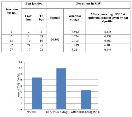
From the table it is observed that normal power loss of the IEEE 30 bus system is 10.809 MW. It may rise to 13.211 MW, when there is a single generator outage problem. The increased power loss can be reduced to
[image:6.612.94.519.238.616.2]6.445 MW by connecting UPFC at optimum location given by proposed algorithm. This shows the effectiveness of the proposed method.
Table.2: Power loss at single generator outage using the proposed method
Generator bus no.
Best location Power loss in MW
From bus
To
bus Normal
Generator outage
After connecting UPFC at optimum location given by bat
algorithm
2 2 4
10.809
13.912 6.445
6 8 28 13.724 6.434
13 12 16 12.795 6.460
22 24 25 13.119 6.400
27 10 22 13.211 6.445
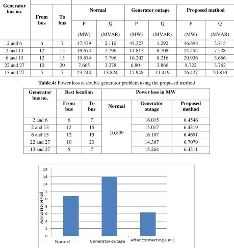
Fig.3 Power loss comparison at single generator outage condition Subsequently, double generator outage is introduced in
the IEEE 30 bus system. At this instant, the power flow of the system is affected. Table 3 gives the details of power flow under normal condition, double generator outage condition and after connecting UPFC at
247 power loss of the IEEE 30 bus system is 10.809 MW. It
may rise to 16.107 MW, when there is a double generator outage problem. The increased power loss can be reduced by connecting UPFC at optimum location
[image:7.612.77.536.204.692.2]given by proposed algorithm. This shows the effectiveness of the proposed method. Figure 3 and Figure 4 shows the power loss comparison at different conditions.
Table.3: Power flow analysis at double generator problem using the proposed method
Generator bus no.
Best location Power flow
From bus
To bus
Normal Generator outage Proposed method
P (MW)
Q (MVAR)
P (MW)
Q (MVAR)
P (MW)
Q (MVAR)
2 and 6 6 7 47.479 2.110 44.327 1.292 46.898 3.715
2 and 13 12 15 19.674 7.796 14.813 8.708 24.454 7.528 6 and 13 12 15 19.674 7.796 16.202 8.216 20.936 3.666
22 and 27 10 20 7.665 3.278 6.801 3.866 8.722 3.762
13 and 27 5 7 23.744 13.824 17.948 11.419 26.427 20.810 Table.4: Power loss at double generator problem using the proposed method
Generator bus no.
Best location Power loss in MW
From bus
To
bus Normal
Generator outage
Proposed method
2 and 6 6 7
10.809
16.015 6.4546
2 and 13 12 15 15.017 6.4319
6 and 13 12 15 16.107 6.4691
22 and 27 10 20 14.367 6.7079
[image:7.612.129.487.378.695.2]248 Fig.4 Power loss comparison at double generator outage condition
5. CONCLUSION
This paper describes about minimization of power loss by optimal location of UPFC given by the bat algorithm. By connecting UPFC at the optimum location, and the power flow has been analyzed. The advantage of the proposed method is capability and robustness to solve the complex optimization problem. In the results, system power flows, power loss was analyzed. The comparison of results proved that the proposed method is the most effective technique to reduce power loss of the power system, which is competent over the other techniques.
REFERENCE
[1] P. Ramasubramanian, G. Uma Prasana, and K. Sumathi, "Optimal Location of FACTS Devices by Evolutionary Programming Based OPF in Deregulated Power Systems", British Journal of Mathematics & Computer Science, Vol.2, No.1, pp.21-30, 2012
[2] Rakhmad Syafutra Lubis, Sasongko Pramono Hadi, and Tumiran, "Selection of Suitable Location of the FACTS Devices for Optimal Power Flow", International Journal of Electrical & Computer Sciences, Vol.12, No.3, pp.38-49, 2012
[3] S.Durairaj, and B.Fox, "Optimal Placement of Facts Devices", International Conference on Energy & Environment, 2008
[4] D. Devaraj, and J. Preetha Roselyn, "Genetic algorithm based reactive power dispatch for voltage stability improvement", International Journal of Electrical Power & Energy Systems, Vol.32, No.10, pp.1151–1156, December 2010
[5] Chaohua Dai, Weirong Chen, Yunfang Zhu, and Xuexia Zhang, "Reactive power dispatch considering voltage stability with seeker optimization algorithm", Electric Power Systems Research, Vol.79, No.10, pp.1462–1471, October 2009
[6] Rahul J. Shimpi, Rajendra P. Desale, Kunal S. Patil, Jaswantsing L. Rajput and Shailesh B. Chavan, "Flexible AC Transmission Systems", International Journal of Computer Applications, Vol.1, No.15, pp.54-57, 2010
[7] P. K. Dash, S. R. Samantaray, and Ganapati Panda, "Fault Classification and Section Identification of an Advanced Series-Compensated Transmission Line Using Support Vector Machine", IEEE Transaction on Power Delivery, Vol.22, No.1, pp.67-73, January 2007
[8] H O Bansal, H P Agrawal, S Tiwana, A R Singal and L Shrivastava, "Optimal Location of FACT Devices to Control Reactive Power", International Journal of Engineering Science and Technology, Vol.2, No.6, pp.1556-1560, 2010
[9] Xuan Wei, Joe H. Chow, Behruz Fardanesh and Abdel-Aty Edris, "A Common Modeling Framework of Voltage-Sourced Converters for Load Flow, Sensitivity, and Dispatch Analysis", IEEE Transactions On Power Systems, Vol.19, No.2, pp.934-941, May 2004
[10] S. V. Ravi Kumar, and S. Siva Nagaraju, "Functionality of UPFC in Stability Improvement", International Journal of Electrical and Power Engineering, Vol.1, No.3, pp.339-348, 2007 [11] Gerbex, S., Cherkaoui, R., and Germond, A.J.,
"Optimal location of FACTS devices to enhance power system security", IEEE Bologna Power Tech Conference Proceedings, 2003
[12] Mori, H., and Goto, Y., "A parallel tabu search based method for determining optimal allocation of FACTS in power systems", International Conference on Power System Technology, 2000 [13] Husam I. Shaheen, Ghamgeen I. Rashed, and
S.J. Cheng, "Optimal location and parameter setting of UPFC for enhancing power system security based on Differential Evolution algorithm", Electrical Power and Energy Systems, Vol.33, pp.94–105, 2011
[14] Seyed Abbas Taher, and Muhammad Karim Amooshahi, "New approach for optimal UPFC placement using hybrid immune algorithm in electric power systems", Electrical Power and Energy Systems, Vol.43, pp.899-909, 2012
[15] A.R. Phadke, and Manoj Fozdar, K.R. Niazi, "A new multi-objective fuzzy-GA formulation for optimal placement and sizing of shunt FACTS controller", International Journal of Electrical Power & Energy Systems, Vol.40, No.1, pp.46–53, September 2012
[16] Chuan Wang, Yancheng Liu, Youtao Zhao and Yang Chen, "A hybrid topology scale-free Gaussian-dynamic particle swarm optimization algorithm applied to real power loss minimization", Engineering Applications of Artificial Intelligence, Vol.32, pp.63-75, June 2014.
249 [18] Abdelaziz Laifa and Mohamed Boudour, "Optimal
Placement and Parameter Settings of Unified Power Flow Controller Device using a Perturbed Particle Swarm Optimization", IEEE International Energy Conference and Exhibition, pp.205-210, 2010 [19] A. Rajabi-Ghahnavieh, M. Fotuhi-Firuzabad, M.
Shahidehpour and R. Feuillet, "UPFC for Enhancing Power System Reliability", IEEE Transactions on Power Delivery, Vol.25, No.4, pp.2881-2890, October 2010.
[20] Xin-She Yang, "Bat Algorithm for Multi objective Optimization", pp.1-12, mar 2012.