Volume 6, No. 1, Jan-Feb 2015
International Journal of Advanced Research in Computer Science
RESEARCH PAPER
Available Online at www.ijarcs.info
ISSN No. 0976-5697
Multiple Direct Data Domain Genetic Algorithm Beamforming Approach to Space
Time Adaptive Processing Using Real Array Elements
Hassan M. Elkamchouchi and Mohamed M. Hassan*
Electrical Department, Engineering Faculty Alexandria University
Alexandria, Egypt
Abstract: This study presents a new multiple direct data domain genetic algorithm beamforming approach to space time adaptive processing using real array elements. Using this new genetic-algorithm-based approach, multiple signals of interest could be handled at the same time. The proposed approach performance will be tested using uniformly spaced real antenna array elements. Hence, received signals by array elements are affected by mutual coupling. The method of moments is used to estimate these mutual coupling effects. Then, the transformation matrix method is used to compensate for these undesired effects. The matrix pencil method is used to estimate the directions of arrival of all coming signals. Finally, the genetic algorithm is used for array multiple beamforming. Numerical examples are used to demonstrate the efficient capability of formed beam patterns to reconstruct more than one signal of interest.
Keywords:Adaptive antennas; mutual coupling; matrix pencil; genetic algorithms; method of moments
I. INTRODUCTION
Adaptive antenna array systems constitute a multiple discipline technology field that has spanned a number of decades in the engineering and scientific community, due to advances in electromagnetic and signal processing [1]. These techniques are considered to be the best methods to handle sever dynamic interference as it has the ability to electronically direct the pattern main lobe to the target direction while also automatically placing deep pattern nulls in the directions of interferers [2].
In direct data domain (D3) methods, which process the data on snapshot by snapshot basis, no assumption is made about the statistics of the environments. Hence, the effect of nonstationarity in the data could be mitigated [3]. D3 methods could be used for space time adaptive processing (STAP). In this case, two dimensional data is collected on snapshot by snapshot basis by an antenna array utilizing space and time diversity for adaptively enhancing signals in a nonhomogeneous environment. The nonhomogeneous environment may consist of nonstationary clutters and could include blinking jammers [4].
Genetic algorithms (GAs) might be more efficient than gradient-based methods for improving the nulling performance of a linear antenna array since the gradient-based methods have following disadvantages:
a. The methods are highly sensitive to starting points when the number of variables, and hence the size of the solution space, increases.
b. The methods frequently converge to local suboptimum solutions.
c. The methods require a continuous and differentiable objective function.
d. The methods require piecewise linear cost approximation (for linear programming).
e. The methods have problems with convergence and algorithm complexity (for non-linear programming). The main advantage of the direct data domain genetic algorithm (D3GA) beamforming approach to STAP [5] is that, in addition to the method ability to maintain the array
beam pattern value at the signal of interest (SOI) direction, it could minimize the side lobes level and hence reduce the energy which will leak from the array through these side lobes. However, D3GA algorithm can handle only one SOI at a time. So, in this study, a new technique for multiple beamforming based on D3GA approach is developed. Using this new algorithm, multiple SOIs could be handled at the same time.
In practical cases, the real antenna array elements spatially sample and reradiate the incident fields. The reradiated fields interact with the other elements causing the sensors to be mutually coupled. Mutual coupling severely degrade the interference nulling capabilities of the D3 algorithms and hence these effects must be evaluated and compensated [2].
The rest of the paper is organized as follows: In section II, the using of the method of moments (MoM) to evaluate the mutual coupling in an array of uniformly spaced thin half-wavelength dipoles will be presented and the transformation matrix approach to the compensation for these mutual coupling effects will be also presented. Section III represents the matrix pencil (MP) method to estimate the directions of arrival (DOAs) of all coming signals. Section IV states a brief description of the D3GA beamforming approach to STAP. Section V presents the new multiple direct data domain genetic algorithm (MD3GA) beamforming approach. Section VI presents the main component of the GA used in this paper. Finally, in section VII, the performance of the proposed new approach will be evaluated using two numerical examples.
II. MUTUALCOUPLINGEVALUATIONAND COMPENSATION
the next two subsections, the evaluation of the mutual coupling effects in an array of uniformly spaced thin half-wavelength dipoles using the MoM will be presented. Then, the compensation for these effects using the transformation matrix method will be illustrated.
A. Mutual Coupling Evaluation:
First, Consider an incident field Einc impinging on a receiving linear antenna array of N parallel thin uniformly spaced dipoles. Each element of the array is identically point loaded at the center with the load impedance ZL. The dipoles
are z-directed, of length L and radius a, and are placed along the x-axis, separated by distance Δx. The array lies in the X-Z plane. Thus the integral equation that relates the incident field to the current on the wires could be written as [2], [3]
(1)
Equation (1) could be solved using MoM. By Considering B (chosen odd) piecewise sinusoids basis functions per element, (1) could be reduced to the matrix equation [6]:
(2)
Where I is the MoM current vector, V is the MoM voltage vector. Z and Y are the MoM impedance and admittance matrices respectively. Assuming that the incident field is linearly polarized; the ith entry in the MoM voltage vector V, corresponding to the qth basis function on the mth antenna, is given by the analytic form [3]
(3)
Where xm is the x-coordinate of the axis of the m
th
antenna, , and is the distance between
two successive basis functions’ centers. An analytic form for the entries of the MoM impedance matrix could be found in [6]. The mutual coupling affected measured voltage at the mth antenna port, , could be computed by [2]
(4)
B. Mutual Coupling Compensation:
In this subsection, the transformation matrix approach to compensate for the undesired electromagnetic effects in a non-uniformly spaced antenna array whose received elements’ signals are affected by the presence of near-field electromagnetic effects using a transformation matrix[3], [7]. Hence, it is required to find the optimal transformation matrix Tm between the real array manifold and the array
manifold corresponding to a ULVA, such that
(5)
In order to find the transformation matrix Tm, we start by
dividing the field of view of the array into sectors. Next, we
define a set of uniformly defined angles to cover each sector such that:
(6)
Where is the step size. Then we measure/ compute the real array manifold corresponding to the set and compute the ULVA array manifold corresponding to the same set . Now the transformation matrix Tmq is
computed for each sector q such that
using the least squares method. The least squares solution for the transformation matrix could be written as
(7)
Where the H superscript represents the conjugate transpose of a complex matrix. The processed input voltage in which the mutual coupling effects and the effects of various near field scatterers have been eliminated, xc(t), could
be written as various signals impinging on an antenna array [3], [8]. For a uniformly spaced linear array composed of N+1 element, the voltage induced in the array nth element, xn, could be written
processing a Hankel matrix as illustrated in [3], [8]. Then, the DOAs of various signals could be obtained as follows:
(10) containing the induced voltages at the array elements.
IV. D3GABEAMFORMINGAPPROACHTOSTAP
constant velocity is considered. The system consists of a linear antenna array with uniformly spaced N elements where each element has its own independent receiver channel and it is also assumed that the system processes M coherent pulses within a coherent processing interval (CPI). Hence, there are NM complex weights to be used for beamforming. Given the DOAs for all the coming signals, a genetic algorithm (GA)
b. Maximizing the pattern value in the direction of the SOI (PS) in order to radiate maximum possible power in this
direction.
c. Placing deep nulls in directions of interferers and also the nulls’ depths will be proportional to the interference incident signals’ intensities.
The fitness function which is supposed to achieve the above objectives could be written as:
(12)
Where J is the number of interferers (jammer) signals, Pi
is the array beam pattern complex value in the direction of the ithjammer, PS is the array beam pattern complex value in
the direction of the SOI, Ni is the ithnormalized pattern null
value corresponding to the ithjammer, and w is the weighting factor used to increase the amplitude of the fitness function’s 1st term, subtraction term, and hence balance the GA
Where W is the complex weights vector obtained by the D3GA beamforming approach, T denotes the transpose of the vector, and is the spatial-temporal steering vector in computed at the kth direction. The ith normalized pattern null value corresponding to the ith jammer, Ni, could be computed mentioning that all pattern values and complex weights will be normalized with respect to Ps. The weights could be used
to reconstruct the SOI using genetic algorithm (MD3GA) beamforming approach to STAP will be presented. This approach is based on the D3GA approach [5] which is capable of maintaining the beam pattern value in the direction of SOI, placing deep nulls in directions of interferers, and minimizing the side lobes level. Hence, this approach outperforms the methods presented in [3], [4], [9], and [12] which have no means to control the side lobes levels. However, the D3GA approach is capable of handling only one SOI at a time. In this study, the D3GA beam pattern values at the directions of the SOIs must have the same complex value. Suppose that there are I SOIs impinging on the array, the fitness function which is supposed to achieve the algorithm objectives will be the same as (12) with an addition of a third term. Hence, the fitness function could be written as
(19) minimizes the fitness function in (19) will be found using the GA. When all SOIs have the same carrier frequency, (18) could be used to reconstruct the sum of all of them. In order to estimate each SOI individually, consider the other SOIs as interferers as it will be demonstrated in the next examples [9], [13], [14], [15].
VI. GENETICALGORITHMCOMPONENTS
current population to be parents and uses them to produce the children of the next population. Over successive generations, the population “evolves” toward an optimal solution which is considered to be the solution which gives the minimum of
a. Genetic representation of solution: Real number encoding is used to represent individual solutions or chromosomes.
b. Population initialization: uniform random initialization is used and the population size is selected to be ten times the number of the antenna array elements taking into consideration that two chromosomes are used to represent each array element complex weight one for the real part and the other for the imaginary part [11].
c. Evaluation of the fitness function: The GA should find the global minimum of the fitness function. d. Fitness scaling: The ranking method in which the
scaling of raw scores is based on the rank of each individual instead of its score is used [11].
e. Selection methods: Stochastic uniform selection method is used. Stochastic uniform selection method lays out a line in which each parent corresponds to a individuals at each generation [10], [11]. In this paper, the most fit two chromosomes survive directly to the next generation as elite chromosomes.
f. Genetic operators: genetic operators are used to produce new individuals. Crossover and mutation are the most frequently used genetic operators and are described as follows: 1- The crossover operator is the exchange of genes between parent’s chromosomes to produce offspring. The scattered crossover method is used. In this method, crossover is done by creating a random binary vector and selecting the genes where the vector's elements are ones from the first parent, and the genes where the vector's elements are zeros from the second parent, and combines the genes to form the child [10], [11]. The fraction of each population, other than elite children, that are made up of crossover children is set to 0.8. The remaining chromosomes are mutation children. 2- Mutation is done by the addition of a random number which is chosen from a Gaussian distribution to each entry of the parent vector.
g. Termination condition: a maximum number of 500 generations is used to terminate GA.
VII.NUMERICALEXAMPLES
In this section, two numerical examples illustrating the effectiveness of the proposed MD3GA beamforming technique will be presented. The examples use a 10-element array of thin half-wavelength long wire dipoles. The z -directed dipoles each have radius and are spaced a half-wavelength apart along the x-axis. Each wire is centrally
loaded with a 50 Ω resistance. Seven unknowns per wire are used in the MoM analysis. The array is operating at 900 MHz and the array vision range is limited to
measured starting from the x-axis. We consider that all the coming signals are in the azimuth plane (θ= ) and these signals are composed of two jammers and two SOIs, also w and M are chosen to be 100 and 16 respectively. The Doppler frequency is fd= 900 Hz, the PRF is 4000Hz, and the CF is
chosen to be 1000 m/V. White Gaussian noise of 26 dB below the 1st SOI is added to the received signals.
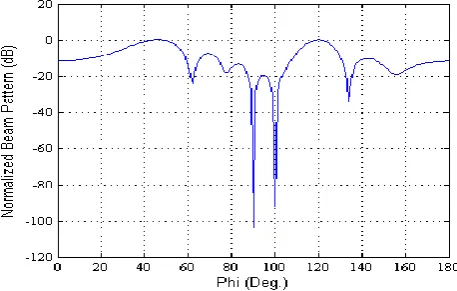
After mutual coupling evaluation, the transformation matrix method is used to compensate for these mutual coupling effects. Then, the MP method is used to estimate the incident signals’ DOAs and the amplitudes of all impinging signals will be also estimated. Finally, the proposed multiple beamforming approach is used to find the weights’ optimal values and then the SOIs are reconstructed using (18). jammers’ intensities and the normalized beam pattern values in the directions of the SOIs are maintained at 0dB. The reconstructed signal, which represents the sum of the incident SOIs, is found to be 2.9862 + 2.0196i. It is also clear that all the side lobes levels, all are below 0dB, are significantly minimized with respect to the results obtained by the multiple beamforming approaches presented in [9], [13], [14], and [15].
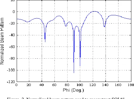
In order to reconstruct one SOI at a time, the other one should be considered as an interferer. Fig. 2 shows the normalized beam pattern in dB when SOI2 is considered as an interferer; one deep null is placed in its direction. Hence, this pattern could be used to reconstruct the 1st SOI, SOI1,
Figure. 2.Normalized beam pattern used to reconstruct SOI #1
Figure 3.Normalized beam pattern used to reconstruct SOI #2
B. Example Two: Varying Signals:
In the second example, the 1st incident SOI intensity is 1 V/m and arriving from the direction and the 2nd incident SOI intensity is varied from 0.2 V/m to 10 V/m and its DOA is varied from ∅=120° to ∅=170°. The 1st jammer intensity is fixed at 50dB over the 2nd SOI and arriving from a fixed direction of while for the 2nd jammer the intensity is varied from 0dB to 50 dB over the 2nd SOI and its DOA is varied from ∅=100° to ∅=110°. All the variations in the amplitudes and the DOAs of the 2nd SOI and 2nd jammer are done over 50 equal steps.
Fig. 4 plots the magnitudes of the actual and the reconstructed SOIs, i.e. the sum of the incident SOIs. As it can be seen, the reconstructed SOIs magnitudes are almost coincide with the actual values. The reconstruction root mean square error (RMSE) is found to be 0.0059V/m; the reconstruction errors are plotted in Fig. 5.
The 1st SOI could be reconstructed by considering the 2nd SOI as an interferer. Fig. 6 shows the actual and the reconstructed 1st SOI magnitudes. The reconstruction RMSE is found to be 0.0049 V/m. Similarly, the 2nd SOI could be reconstructed by considering the 1st SOI as an interferer. Fig. 7 shows the 2nd SOI actual and reconstructed magnitudes and the corresponding reconstruction errors are shown in Fig. 8. The 2nd SOI reconstruction RMSE is found to be 0.0054 V/m.
Figure 4.Magnitudes of actual and reconstructed SOIs (V/m)
Figure 5.SOIsmagnitudes’ reconstruction errors (V/m)
Figure 7.Magnitudes of actual and reconstructed SOI #2 (V/m)
Figure 8.SOI #2magnitudes’ reconstruction errors (V/m)
VIII.REFERENCES
[1] A. Svendsen, and I. Gupta, “The effect of mutual coupling on the nulling performance of adaptive antennas,” IEEE Antennas and Propagation Magazine, vol. 54, no. 3, June 2012, pp. 17 – 38.
[2] R. Adve and T. Sarkar, “Compensation for the effects of mutual coupling on direct data domain adaptive algorithms,” IEEE Transactions on Antennas and Propagation, vol. 48, no.1, January 2000, pp. 86 - 94.
[3] T. Sarkar, M. Wicks, M. Salazar-Palma, and R. Bonneau, Smart Antennas. Wiley-IEEE Press, 2003.
[4] T. Sarkar, H. Wang, S. Park, R. Adve, J. Koh, K. Kim, Y. Zang, M. Wicks, and R. Brown, “Deterministic least-squares approach to Space–Time Adaptive Processing (STAP),” IEEE Transactions on Antennas and Propagation, vol. 49, no.1, January 2001, pp. 91 - 103.
[5] H. Elkamchouchi and M. Hassan, “Space time adaptive processing using real array elements based on direct data domain adaptive nulls genetic algorithm beam forming,” Proc. the Int. Conf. Electronics and Communication System. Coimbatore (India), 2014, pp.183-187.
[6] B. Strait, T. Sarkar, and D. Kuo, “Special programs for analysis of radiation by wire antennas,” Syracuse Univ. Tech. Rep. AFCRL-TR-73.0399, June 1973.
[7] K. Kim, T. Sarkar, and M. Palma, “Adaptive processing using a single snapshot for nonuniformaly spaced array in the presence of mutual coupling and near-field scaterrers,” IEEE Transactions on Antennas and Propagation, vol. 50, no.5, May 2002, pp. 582- 590.
[8] T. Sarkar, and O. Pereira, “Using the matrix pencil method to estimate the parameters of a sum of complex exponentials,” IEEE Antennas and Propagation Magazine, vol. 37, no.1, May 1995, pp. 48 – 55.
[9] W. Ellatif, “Smart Antennas: Space Time Adaptive Processing Based on Direct Data Domain Least Squares Using Real Elements,” Ph.D thesis, electrical engineering, Alexandria university, 2011.
[10] M. Hassan, “A Proposed Fault Identification Scheme in Systems Using Soft Computing Methodologies,” M.Sc. thesis, electrical engineering, Alexandria university, 2008.
[11] Genetic Algorithm and Direct Search Tool Box User’s Guide. The MathWorks, Inc., 2006.
[12] H. Elkamchouchi, D. Mohamed, W. Ali, and M. Omar, “Space time adaptive processing (STAP) using uniformly spaced real elements based on direct data domain least squares (D3LS) approach,” Proc. ICMMT – International Conference on Microwave and Millimeter Wave Technology, Ghengdu(China), 2010, pp.1360-1363.
[13] W. Choi and T. Sarkar, “Multiple beamforming technique using direct data domain least squares (D3LS) approach,” IEEE Antennas and Propagation Society int. Symp., 2006, pp. 3315-3318.
[14] H. Elkamchouchi, D. Mohamed, and W. Ali, “Multiple constraint space time adaptive processing (STAP) using real elements based on direct data domain least squares (D3LS) approach,” Proc. 27th NRCS 2010-National Radio Science Conference, March 2010, Egypt.