---
-
- - -
-
-
--
---- ----
-
---
---_
.
-
3745 Communication Controller
Maintenance Information Reference (MIR)
Part 1
co co co
D
..
co coIII
..
---
---
-
..
-_
....
..
- .----
....
---
-~-,-IBM 3745 Communication Controller
Models 210,310,410, and 610
IBM 3746 Expansion Unit
Models A11, A12, L 13, L 14, and L 15
Maintenance Information Reference (MIR)
Part 1
Note!
Before using this information and the product it supports, be sure to read the general
information under "Notices" on page ix.
Seventh Edition (August 1991)
The information contained in this manual is subject to change from time to time. Any such changes will be reported in subsequent revisions. Changes have been made throughout this edition, and this manual should be read in its entirety.
Order publications through your IBM representative or the IBM branch office serving your locality. Publications are not stocked at the addresses given below.
A form for readers' comments appears at the back of this publication. If the form has been removed, address your comments to:
International Business Machines Corporation Department 6R1 LG
180 Kost Road
Mechanicsburg PA 17055-0180 U.S.A.
or
IBM France
Centre d'Etudes et Recherches Service 0762 BP 79
06610 La Gaude France
When you send information to IBM, you grant IBM a non-exclusive right to use or distribute the infor-mation in any way it believes appropriate without incurring any obligation to you.
©
Copyright International Business Machines Corporation 1988, 1991. All rights reserved.Contents
Part 1
Chapter 1. General Information
Introduction . . . .
Modes of Operation . . . .
Machine Identification and Capacity 3745 Model Identification . . . . Frame Locations . . . . IBM 3745 Programming Support Using the 3745 Library for Service Preventive Maintenance
Maintenance Philosophy Maintenance Aids
1-1 1-2 1-8 1-10 1-10 1-11 1-19 1-22 1-24 1-24 1-24
Chapter 2. Central Control Unit (CCU) 2-1
The CCU in 3745 Data Flow 2-2
General Description . . . . 2-3
Functional Description . . . 2-4
CCU Environment 2-12
Main Storage . . . 2-14
CCU to/from Storage 2-19
CCU to/from Adapters (CA-LA) 2-23
CCU to/from MOSS . . . 2-46
CCU Diagnostics . . . 2-47
Problem Isolation Procedure for 210-to-410 or 3'10-to-610 Model Upgrade . 2-55
Chapter 3. Buses and Bus Switching . . . .
The Buses and Bus Switching in 3745 Data Flow
Generalities .. . . .
Bus Switch
Buses . . .
Adapter Addressing .
Bypass Mechanism for LAs Bypass Mechanism for CAs
Extended Troubleshooting: Adapter Bus Problem Isolation
Chapter 4. Transmission Subsystem (TSS)
Low Speed Scanner (LSS)
LlC Unit (LlU) . . . . Serial Link (SL) . . . . Communication Scanner Processor (CSP) Card
Front End Scanner (FES) . . . .
Front End Scanner Adapter (FESA) . . . .
Serial Link (SL) . . . .
Double Multiplexer Card (DMUX) . . . . .
Single Multiplexer Card (SMUXA/B)
LlCs Type 1 to 4 Cards . . . .
LlCs Type 5 and 6 DTE Function
LlC Type 5 DCE Function . . . .
3-1 3-2 3-3 3-4 3-23 3-55 3-72 3-80 3-84 4-1 4-8 4-10 4-15 4-16 4-27 4-31 4-38 4-40 4-44 4-49 4-59 4-62
L1C Type 6 DSU/CSU Function . . . ; . . .
Scanner Microcode . . . .
Microcode Interaction with the Control Program Microcode Interaction with FES
Microcode Interaction with MOSS
Instruction Operation . . .
External Registers Description FES RAM A Description FES RAM B Description . FES RAM C Descri ption . Error Detection . . . . Reporting Errors to the CCU Reporting Errors to the MOSS Miscellaneous Status Fields Error Status Description
Problem Determination Aids for LlC1s to L1C4s Problem Determination Aids for LlC5s and L1C6s
Chapter 5. The Token-Ring Subsystem The TRSS in 3745 Data Flow . . . . . Token-Ring Network . . . . The Token-Ring Adapter in the 3745 Token-Ring Interface Coupler (TIC) Card Token-Ring Multiplexor (TRM) Card Machine Internal Communications Programmed Input/Output Operations PIO Functional Description . . . . PIO/MMIO Hand-Shaking Mechanism PIO Format and Types
TRM PIO Command Description TRM Cycle Steal Operations .. TRM Interrupt Operations
TRA Disconnect/Connect Function TRA Resets . . . . Error Detection and Reporting .. TRA Interaction with Control Program Problem Determination Aids . . . .
Chapter 6. High Performance Transmission Subsystem (HPTSS) HPTSS in 3745 Data Flow . . . .
Introduction . . . . Internal Interconnections . . . . Communication Scanner Processor (CSP) Front End Scanner High-Speed (FESH) NCP-to-CSP Command Flow ..
Transmit Operation . . . .
Receive Operation . . . . Modem Interface Management
Microcode Interaction with Control Program Microcode Interaction with MOSS
HSS Registers . . . .
Error Detection and Reporting Miscellaneous Status Fields Problem Determination Aids Communication Interfaces
iv
IBM 3745 Maintenance Information Reference (MIR)Part 2
Chapter 7. Channel Adapter (CA) . . . . . The Channel Adapter in 3745 Data Flow . Introduction . . . .
CA Operating Environment '"
Overall Operation . . . .
Input/Output Instruction Format CA Instructions (Register Contents) Autoselection . . . .
Cycle Steal . . . .
CA Interface Enabling/Disabling CA/MOSS Connection . . . . . Interrupt Requests . . . . Control Character Recognition Two-Processor Switch (TPS) CA Error Condition
Channel Stop . . . . Interface Disconnect I/O Error Alert
CA Concurrent Maintenance (CACM) Testing and Checking Hardware Channel Monitoring
CA Initialization . . . .
Chapter 8. Maintenance and Operator Subsystem (MOSS) Introduction . . . .
MOSS Reset MOSS Functions MOSS States MOSS Microcode MOSS Interrupt Levels Detection of MOSS Errors MOSS/CCU Communication
MOSS/CCU Adapter (MCCU) Registers MOSS/CA Adapter (MCAD) Registers MOSS/SWL Adapter (SWAD) Registers Branch Trace . . . .
Address Compare . . . . Mailbox Description . . . . MOSS/Line Adapter Communication
LSSD Operation . . . .
MOSS/Disk Drive Interaction
MOSS/Operator Console Connections
Chapter 9. Control Panel, Operator Consoles, Disk/Diskette Drives Control Panel . . .
Operator Consoles Disk/Diskette Drive
Chapter 10. 3745 Power System The Power System in 3745 Data Flow Introduction . . . .
AC Voltages Input . . . .
7-1 7-4 7-5 7-10 7-11 7-14 7-16 7-43 7-45 7-46 7-46 7-47 7-48 7-49 7-53 7-55 7-55 7-56 7-56 7-57 7-60 7-61 8-1 8-3 8-4 8-6 8-7 8-9 8-10 8-11 8-14 8-15 8-18 8-21 8-24 8-26 8-30 8-34 8-35 8-37 8-38 9-1 9-2 9-6 9-9 10-1 10-3 10-4 10-4
Power Control Subsystem Power Mode of Operation Power ON/OFF Sequence POR from Power Control Maintenance
Chapter 11. IML and IPL
IPL Initialization . . .
Controller Initialization IPL Structural Description MOSS IML Description
Scanner IML Step Description Timed IPL . . . .
Chapter 12. Error Logging . Introduction . . . . BER Generalities . . . . BERs Which Are Not Machine Errors Specific Mechanisms
AutoMaint . . . . BER Recovery Procedures . Unresolved Interrupts .. MOSS BER Type 01 Diagnostics BER Type 03
Power BER Type 04 .
NCP ESS BER Type 08 NCP CA BER Type 10
NCP TSS/HPTSS BER Type 11 NCP/PEP BER, Type 12 NCP CCU BER Type 13 NCP IOC BER Type 14 NCP TRSS BER Type 15
Chapter 13. Traces, Dumps and File Transfer
Traces . . . .
Traces in an ACF/VTAM Environment Host Traces (Environment-Independent) External Scanner Interface Trace . . . . Internal Scanner Interface Trace
Scanner Microcode Checkpoint Trace Internal Channel Adapter Trace .. .
LOGREC Display With EREP . . . . .
Dumps and File Transfer to the Host
Chapter 14. Ethernet Subsystem (ESS)
ESS in 3745 Data Flow . . . .
Introduction . . . . Frame Types Supported
ELA Microcode Description . . . . .
Internal Interconnections . . . . Communication Scanner Processor (CSP)
Ethernet LAN Coupler Card (EAC) . . . .
NCP-to-CSP Command Flow . . . . Microcode Interaction With Control Program
Parameter/Status Area Layout . . . .
vi
IBM 3745 Maintenance Information Reference (MIR)ELA Command Description . . . Microcode Interaction With MOSS
ELA Registers . . . .
Error Detection and Reporting . Problem Dete"rmination Aids
List of Abbreviations
Glossary ..
Bibliography . . . .
3745 Models 210, 310, 410, and 610 Customer Documentation 3745 Models 210, 310, 410, and 610 Service Documentation.
Index . . . .
14-32 14-39 14-42 14-50 14-59
X-1
X-11
X-17 X-17 X-18
X-19
Notices
References in this publication to IBM products, programs or services do not imply that IBM intends to make these available in all countries in which IBM operates. Any reference to an IBM product, program, or service is not intended to state or imply that only IBM's product, program, or service may be used. Any functionally eq·uivalent product, program, or service that does not infringe any of IBM's intellectual property rights may be used instead of the IBM product, program, or service. Evaluation and verification of operation in con-junction with other products, except those expressly designated by IBM, is the user's responsibility.
IBM may have patents or pending patent applications covering subject matter in this document. The furnishing of this document does not give you any license to these patents. You can send license inquiries, in writing, to the IBM Director of Commercial Relations, IBM Corporation, Purchase, NY 10577, U.S.A.
Electronic Emission Notices
Federal Communications Commission (FCC) Statement
Note: This equipment has been tested and found to comply with the limits for a Class A digital device, pursuant to Part 15 of the FCC Rules. These limits are designed to provide reasonable protection against harmful interference when the equipment is operated in a commercial environment. This equipment gen-erates, uses and can radiate radio frequency energy and, if not installed and used in accordance with the instruction manual, may cause harmful interfer-ence to radio communications. Operation of this equipment in a residential area is likely to cause harmful interference, in which case the user will be required to correct the interference at his own expense.
Properly shielded and grounded cables and connectors must be used in order to meet FCC emission limits. IBM is not responsible for any radio or television interference caused by using other than recommended cables and connectors or by unauthorized changes or modifications to this equipment. Unauthorized changes or modifications could void the user's authority to operate the equip-ment.
This device complies with Part 15 of the FCC Rules. Operation is subject to the following two conditions: (1) this device may not cause harmful interference, and (2) this device must accept any interference received, including interfer-ence that may cause undesired operation.
For Canada, Canadian Department of Communication Statement, GX27-3883, applies.
Trademarks and Service Marks
The following terms, denoted by an asterisk (*), used in this publication, are
trademarks or service marks of IBM Corporation in the United States or other countries:
IBM NetView RETAIN
LPDA OS/2
YES
MVS PS/2 VTAM
The following terms, denoted by a double asterisk (**), used in this publication,
are trademarks of other companies:
Ethernet Xerox Inc.
Product Safety Information
General Safety
Safety Notices
This product meets IBM* safety standards.
For general safety information, see:
• Telecommunication Products Safety Handbook, GA33-0126
See Safety Notices located at the beginning of the Maintenance Information
Pro-cedures manual, SY33-2054.
Service Inspection Procedures
The Service Inspection Procedures helps service personnel check whether the 3745 conforms to IBM safety criteria. They have to be used each time the 3745 safety is suspected.
The Service Inspection Procedures section is located at the beginning of the
3745 Maintenance Information Procedures (MIP) manual.
The 3745 areas and functions checked through service inspection procedures are:
1. External covers 2. Safety labels
3. Safety covers and shields 4. Grounding
5. Circuit breaker and protector rating 6. Input power voltage
7. Power-ON indicator 8. Emergency power OFF.
About This Book
This manual provides:
1. Introductory and how-to-fix information
2. Information for maintaining CSAs (Common Sub-assemblies) 3. Description of IBM 3745 Communication Controller functional units.
The console(s) and operator panel procedures are not provided in this manual, but are provided in the:
• 3745 Advan(;ed Operations Guide, SA33-0097, and 3745 Service Functions, SY33-2055, for the maintenance functions used by service personnel.
• 3745 Basic Operations Guide, SA33-0098, for the control panel functions.
Who Should Use This Book
This manual is intended for the product support-trained CE (PST CE) to service the IBM 3745 Communication Controller whenever the product-trained CE (PT eE) cannot repair the machine using the Maintenance Information Procedures (MIP) manual.
The person using this Maintenance Information Reference (MIR) manual should:
• Have an understanding of the telecommunications environment. • Be trained to service the 3745 Communication Controller.
• Be familiar with the data circuit terminating equipment (modems, autocall units, and- so on) and the terminals that attach to 3745s.
• Be familiar with the host channel to which the 3745 can be attached.
Service Personnel Definition
See Maintenance Information Procedures manual.
How to Use the Maintenance Library
Maintenance on the 3745 is performed only when a failure or suspected failure occurs in the machine. The customer is first expected to perform problem determination to see if a 3745 problem exists. He uses the Problem Determi-nation Guide and a host or 3745 console to perform the requested procedures. The problem determination guide generally produces a reference code that the customer should provide to the Hardware Central Service (HCS)
If the HCS is contacted, they will confirm that the initial problem determination has been done correctly, and determine if a hardware failure is indicated. Where hardware replacement is required, the HCS will determine which FRU(s) should be replaced, and dispatch a CE with the information needed to identify and replace them. When replacement has been completed, the CE will test the machine as directed by the MIP and Service Functions manuals, to verify ,the repair.
At this point, the Maintenance Information Procedures portion of the 3745 Main-tenance Library has been exhausted. If additional problem analysis is required, the CE should contact the HCS for assistance, since the problem may require special tools or techniques that are described in the Maintenance Information Reference and Service Functions manuals, and are applied by a Product Support-Trained CE.
For more details, see "Maintenance Philosophy" in Chapter 1.
Where to Find More Information
See "Bibliography" page X .. 17.
Summary of Changes
This revised edition gives information concerning the Ethernet**/IEEE 802.3 local area network feature and the new 3745 models 310 and 610.
This edition also corrects minor errors or omissions.
© Copyright IBM Corp. 1988, 1991
Part 1 contain's Chapters 01 to 06, the Abbreviation list, Glossary, and Index.
Chapter 1. General Information
Introduction . . . . ControHer Organization 3745 Data Flow
Console Summary Modes of Operation
Machine Identification and Capacity
3745-210 or 310 (Base Frame or Frame 01) 3745-410 or 610 (Base Frame or Frame 01) 3746-A 11 (Frame 02)
3746-A12 (Frame 03) 3746-L 13 (Frame 04) 3746-L 14 (Frame 05) 3746-L 15 (Frame 06) 3745 Model Identification Frame Locations . . .
Base Frame, Frame 01 Component Locations Adapter Frame, Frame 02 Component Locations Adapter Frame, Frame 03 Component Locations Line Frame, Frame 04 Component Locations Line Frame, Frame 05 Component Locations Line Frame, Frame 06 Component Locations IBM 3745 Programming Support
Controller-Resident Programs . . . . Host-Resident Programs . . . . Generating and Loading the Control Program Migration/Coexistence . . . . Using the 3745 Library for Service . . . .
Remote Service From Hardware Central Service (HCS) On Site Service
Preventive Maintenance Maintenance Philosophy Maintenance Aids
Tools and Test Equipment
© Copyright I BM Corp. 1988, 1991
Introduction
Controller Organization
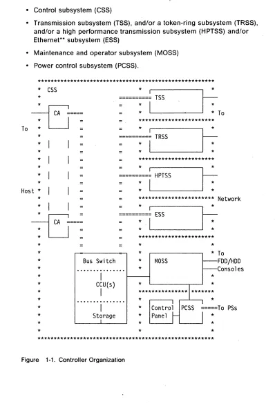
The IBM 3745 communication controller is composed of a:
• Control subsystem (CSS)
• Transmission subsystem (TSS), and/or a token-ring subsystem (TRSq), and/or a high performance transmission subsystem (HPTSS) and/or Ethernet** subsystem (ESS)
• Maintenance and operator subsystem (MOSS) • Power control subsystem (PCSS).
******************************************************
*
CSS
*
*
:=====:=tL.--TS.,--S
--"---II:
To
*
~===:
To
:
~
=
*
***********************
*
~===~IL.--TR_SS _---I~
*
*
************************
:=====~==t
HPTSS
1-":-**=
* ... ---'.
*
*
Host
*
*
***********************Network
*
I
I
:6
*
CA ====:
*
=
*
*
~====~==t
ESS
1-":-** =* ... ---'.
***********************
* *
*
* *To
*
Bus Switch
*MOSS
FDD/HDD
*
Consoles
*
...
*
I
** *
*
CCU(s)
*
I
*
...
* ** *
PCSS =====To PSs
*
Storage
*Panel
** * *
* * *
******************************************************
Figure 1-1. Controller Organization
[image:21.612.122.520.140.728.2]Control Subsystem
The control subsystem (CSS) controls data transfer through the channel inter-face and executes the control program (NCP, or PEP).
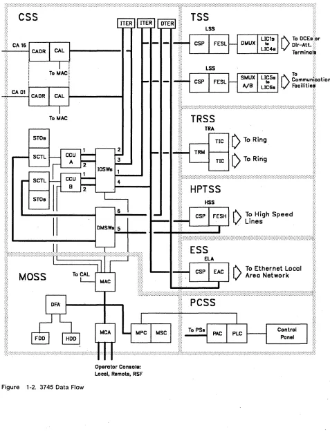
See Figure 1-2 on page 1-6.
It is composed of the central control unit (CCU) with its associated storage (STO), up to eight megabytes, and storage control (SCTL) with the IOC bus switch (IOSW), and the DMA bus switch (DMSW) for direct memory a,ccess (DMA), if the HPTSS is installed.
Two CCUs can be installed to obtain more availability or better performances.
For more details on the CCU, see Chapter 2, "Central Control Unit (<;CU)."
Each CCU controls its associated adapters via two IOC buses, and one DMA bus. A bus switch allows attaching all the adapters to one CCU or to the other, or attaching one group of adapters to one CCU and the remaining group to the other CCU.
For more details on the buses and bus switch, see Chapter 3, "Buses and aus Switching. "
Channel Adapter: The channel adapters (CA) are part of the control subsystem.
Each channel adapter is composed of a channel adapter logic card (CAL), and a channel adapter driver receiver card (CADR).
Two types of <;ttannel adapter are av~ilab~~:
• Channel adapter type 6: Channel adapter data streaming (CADS)
• Channel adapter type
7:
Buffer chaining channel adapter (BCCA). For more details on the channel adapter, see Chapter 7, "Channel Adapter (CA)."Transmission Subsystem
The transmission subsystem (TSS) includes up to 32 low-speed scanners (LSS), also called line adapters (LA). One LSS is composed of a communication scanner processor (CSP) and a front-er)d low-speed scanner (FESL). This LSS is associated with a multiplex card (DMUX or SMUXA/B).
One DMUX controls up to eight line interface couplers (L1Cs). One SMUXA controls up to 16 line interface couplers (L1Cs). One SMUXB controls up to eight line interface couplers (L1Cs).
Three types of L1C, L1Cs type 1, 3, and 4 are attached to the DMUX card.
Two types of L1C, L1Cs type 5 and 6 are attached to the ~M!JXA card or SMUXB card. L1Cs 5 and 6 have the DeE function integrated along with the DTE func-tion.
Configuration Flexibility: The interconnection between the FESL and the DMUX or the SMUXA/B depends on the machine's configuration.
Any FESL card can be connected to any DMUX or SMUXA/B card.
See Figure 1-2 on page 1-6.
For more details on the transmission subsystem, see Chapter 4, "Transmission Subsystem (TSS)."
Token-Ring Subsystem
The token-ring subsystem (TRSS) includes up to four token-ring adapters (TRAs). The TRA is composed of one token-ring multiplexor card (TRM), and two token-ring interface couplers (TICs).
The TRA occupies one CSP address position, and allows attaching two token-rings via TIC cards.
Two types of TIC are available on the 3745:
• TIC type 1 (TIC1) attaches a token-ring operating at 4 Mbps only. • TIC type 2 (TIC2) attaches a token-ring operating at 4 or 16 Mbps.
See Figure 1-2 on page 1-6.
If a TRA is not installed and there are line adapters (LA) following this missing TRA, a bus propagation card BPC2 must be installed in the TRM's card unused position.
For more details on the token-ring subsystem, see Chapter 5, "The Token-Ring Subsystem. "
High Performance Transmission Subsystem
The high performance transmission subsystem (HPTSS) includes up to eight high-speed scanners (HSS), also called line adapters (LA). One HSS is com-posed of a communication scanner processor (CSP) and a front-end high-speed scanner (FESH). The FESH interfaces with main storage via a DMA bus.
The HSS can be installed in all 3745 models in the ELA positions.
Lines cables are connected directly to the FESH card, via the tail gate.
See Figure 1-2 on page 1-6.
For more details on the high performance transmission subsystem, see Chapter 6, "High Performance Transmission Subsystem (HPTSS)."
Ethernet Subsystem
The Ethernet subsystem (ESS) includes up to eight Ethernet LAN adapters (ELA), also called line adapters (LA). One ELA is composed of a communi-cation scanner processor (CSP) and an Ethernet adapter card (EAC). The EAC interfaces with main storage via a DMA bus.
The ELA can be installed in all 3745 models in the HSS positions.
Interfaces
Lines cables are connected directly to the EAC card, via the tail gate.
See Figure 1-2 on page 1-6.
For more details on the Ethernet subsystem, see Chapter 14, "Ethernet Sub-system (ESS)."
The communication controller interfaces with the user network via the trans-mission interface. The communication controller interfaces with the' host processor(s) via the channel interface.
Maintenance and Operator Subsystem
The maintenance and operator subsystem (MOSS) provides the operating and service facilities to the customer's operator and to the customer engineer (CE).
The MOSS consists a processor and storage, a flexible diskette drive (FDD), a hard disk drive (HOD), their adapter (DFA), and a MOSS console adapter (MCA) for connection to:
• A local console (mandatory),
• A remote console (optional) in start-stop mode with a modem and a switched communication facility, or
• An alternate console (optional), direct-attached (without modem), within a distance of 120 meters,
• A link-attached remote service facility (RSF) console (optional) with a modem in BSC mode, and a switched communication facility.
The interconnection with the CCU is performed through a MOSS adapter card (MAC).
The interconnection with the control panel and the power control is performed through a power logic card (PLC).
See Figure 1-2 on page 1-6.
For more details on the MOSS, see Chapter 8, "Maintenance and Operator Subsystem (MOSS)."
For more details on the control panel and consoles, see Chapter 9, "Control Panel, Operator Consoles, Disk/Diskette Drives."
Power Control Subsystem
The power control subsystem (PCSS) is basically made of a power logic card (PLC) and a power analog card (PAC). The PLC card is linked to the secondary power control card of each power supply via a power control bus (PCB). The PLC also links the control panel to the MPC card of the MOSS.
The PAC card generates the power analog signals.
See Figure 1-2 on page 1-6.
For more details on the power control subsystem, see Chapter 10, "3745 Power System."
3745 Data Flow
•• CADR
I
CAt.) ....Termlnal~
LSS
.:.1:.'.: . • :. To MAC
I
r\.
~~mmunl~tion
V
Facilitie~L . - . . . _ - - ' - _ - - - - I
To MAC
iil"""""~'~"~"~"""""'"''''''''''''''''''''"",',',',',',',',','"",',',',','""',',',',,,','.'""'.,.,."'.,.,
•••
,)!:
TRA "
STOs
TIC
[) To Ring.
STOs
6
II
DMSWs 5...
--ill
1 1~
/\:':':':':':"':""':':':"':':':':':':':'1:11"":':':p'2:~'~:""""':"':"':':':':':':':':{'7'::::':;.::\.::.,.:
•• :.:.:':.:.: •••••••
:;.,::.,,',','::,,:::::::::![I •MOSS
....
;:: "',.,.,' •• ,., ••• ,.""".".",'."",,,,""""""",.,"",.,""""",.,""""""',.,.,.,"", .... ::: r-r.-; ... ,"""""""""", ••
,"""',.,"',.,"""""".""",."""""."""I:t,." ...
"."",."'",'",.,',.,',',',""'",.",',"",',,,'.',',',"""""""""""",.",.,.,."",.,.::::,1".,""""""""'"
Operator Cansols:
Local. Remote. RSF
Figure 1-2. 3745 Data Flow
[image:25.612.43.520.99.730.2]Console Summary
============
HOST
4 5
0
0R
2A
1. Local console (mandatory)
3745
SS Port
Switched
Network
sse
Port
Switched
Network
RETAIN
System
2A. Alternate console (direct-attached within 120 meters)
2B. Remote console
3. IBM RSF console
4. Access method console
5. NetView* console.
Modes of Operation
The 3745 can be equipped with one or two CCUs. Each CCU is connected to two IOC buses and one DMA bus if HPTSS is installed. These buses can be switched from one CCU to the other under MOSS control, and provide the fol-lowing modes of operation:
1. Single
A single CCU is installed. All IOC buses are connected to this CCU. No possibility of backup.
Normal Mode
Backup Mode
ccu
Adapters
No Backup
2. Twin standby
Two CCUs are installed. One CCU is active, and the other is in standby, ready to take over if the active CCU fails. If one CCU is failing there is therefore no performance or network degradation.
Normal Mode
Backup Mode
r
Active CCU
CCU
Adapters
CCU
Adapters
I
CCU-A
I
I
CCU-8f
/-'----1
L
Standby CCU
L
Active CCU
3. Twin backup
The two CCUs are simultaneously operational, each controlling part of the network.
If one CCU fails the other CCU takes over the entire resources, with a pos-sible reduction of performances.
Norma 1
~fodeBackup Mode
ccu
Adapters
ccu
Adapters
ICCU-AI
4. Twin dual
The two CCUs are simultaneously opreational, each controlling part of the network. There is no provision for an automatic bus switching and so if one CCU fails a part of the network is lost.
This mode of operation can be considered as operating two different machines in the same box.
Normal Mode
Backup Mode
ccu
Adapters
ccu
Adapters
No Backup
Machine Identification and Capacity
3745-21~0
or 310 (Base Frame or Frame 01)
• One CCU.• Up to eight line adapters (LSS, HSS, or ELA). • Up to 128 lines (speed up to 256 kbps), or
• Up to eight high-speed lines (speed up to 2 million bps), or • Up to 16 Ethenet lines (speed up to 10 million bps), or
• Up to four token-ring adapters (eight token-rings), via four token-ring multiplexers.
• Up to eight channel adapters (CA), or
• Up to four CAs with four TPSs (two-processor switches). • Four or eight megabytes of storage.
• Console attachments.
3745-410 or 610 (Base Frame or
-Frame
01)
Same as the 3745-210 or 310 with two CCUs installed.
3746-A11 (Frame 02)
• Up to 16 line adapters (LSS) • Up to eight channel adapters,
• Or up to four CAs with four TPSs (two-processor switches).
3746-A12 (Frame 03)
• Up to eight line adapters (LSS).
3746-L 13 (Frame 04)
• Up to 256 lines.
3746-L 14 (Frame 05)
• Up to 256 lines.
3746-L 15 (Frame 06)
• up to 256 lines.
3745 Model Identification
Four models are available:
1. Model 210: 3745 equipped with only one CCU, TCM type (thermal conduction module).
2. Model 310: 3745 equipped with only one CCU, PUC type (processor unit card).
3. Model 410: 3745 equipped with two CCUs, TCM type (thermal conduction module).
4. Model 610: 3745 equipped with two CCUs, PUC type (processor unit card).
Frame Locations
• Frame 01 (3745 all models) for base frame
• Frame 02 (3746-A 11) for an extension of up to 16 LAs (LSS) and eight channel adapters
• Frame 03 (3746-A 12) for an extension of up to eight LAs (LSS) • Frame 04 (3746-L 13) for an extension of up to 256 lines.
• Frame 05 (3746-L 14) for an extension of up to 256 lines.
• Frame 06 (3746-L 15) for an extension of up to 256 lines.
3746-L15
Expansion
Unit
Frame 86
Four
LIC Uni t
3746-L14
Expansion
Unit
Frame 8S
Four
LIC Uni t
3746-L13
Expansion
Unit
Frame 84
Four
LIC Uni t
1 =
LSS, HSS,
ELA~or TRA
2
=
LSS only
3745-
or
219/319
3745-419/619
Base Frame
Frame 81
MOSS
· LAl and
CCU (s)
· CA Board
· and Two
· LIC Uni ts
Figure 1-3. Frame Locations (Front View)
3746-All
Expansion
Unit
Frame
02LA2 and
CA Board
3746-A12
Expansion
Unit
Frame 83
LA2
Board
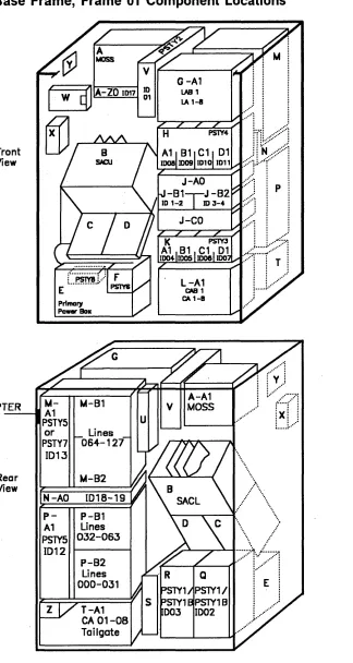
Base Frame, Frame 01 Component Locations
Front
ViewPTER
Rear
View
~A-ZOID17
r1J
Primary
Power Box
M-
h.4-B1 A1PSTY5
or
LinesPSTY7
064-127 ID13h.4-B2
N-AO [018-19
P- P-B1
A1 Lines
PS1Y5 032-063
ID12
P-B2 Lines 000-031
L-A1
CAB 1 CA 1-l!J
:Jft.1:;:~;;:),
P
...•
~-~-;'/'/
... \ .. >
.: ....
::·:::::·r::·::'1
.,/J .. /./
Figure 1-4. Base Frame, Frame 01 Component Locations
[image:31.612.49.373.76.684.2]A
MOSS board and fan N Fan for LlC unitSee Chapter 8, "Maintenance and Operator See "PS Type 5 Frame 01 Connection Subsystem (MOSS)" on page 8-1, or Layout" on page 10-25 for PS type 5 details, "Power Supply Type 2 (PS Type 2)" on or "PS Type 7 Frame 01 Connection Layout" page 10-14 for details. on page 10-32 for PS type 7 details.
B
CCUs control board: See Chapter 2, P LlC unit (from line 00 to line 63 for LlCs 1-4) "Central Control Unit (CCU)" on page 2-1. See Chapter 4, "Transmission SubsystemC CCU-A for models 210 and 410: See (TSS)" on page 4-1,
Chapter 2, "Central Control Unit (CCU)" on or "PS Type 5 Frame 01 Connection Layout"
page 2-1. on page 10-25 for PS type 5 details.
0 CCU-8 for model 410: See Chapter 2, Q PS type 1 or 18, PS for CCU-A.
See "Power Supply Type 1/18" on page 10-9 "Central Control Unit (CCU)" on page 2-1.
or 10-12.
E
Primary power box and PS type 8R PS type 1/1 B, PS for CCU-B. See" Power Supply Type 8 (PS Type 8)" on
See "Power Supply Type 1/1B" on page 10-9 page 10-36 for PS type 8.
or 10-12.
F PS type 6, PS for power supplies control
S Host cable (EPO) connector tail gate. See "Power Supply Type 6 (PS Type 6)" on
See pages YZ043 and YZ543. page 10-29.
G Line adapter board (LSS, TRA, HSS, ELA) T Channel adapters 01 to 08 tail gate.
See Chapter 7, "Channel Adapter (CA)" on See Chapter 4, "Transmission Subsystem
page 7-1. (TSS)" on page 4-1, or Chapter 5, "The
Token-Ring Subsystem" on page 5-1, or U HSS/ELA/TRA tail gate, console and cus-Chapter 6, "High Performance Transmission tomer power control connectors.
Subsystem (HPTSS)" on page 6-1. See Chapter 6, "High Performance Trans-Chapter 14, "Ethernet Subsystem (ESS)" on mission Subsystem (HPTSS)" on page 6-1,
page 14-1. or Chapter 5, "The Token-Ring Subsystem"
H PS type 4, up to four PS, one PS for two LAs on page 5-1, or Chapter 9, "Control Panel, Operator Consoles, Disk/Diskette Drives" on See "PS Type 4 Frame 01 Connection
page 9-1. Chapter 14, "Ethernet Subsystem Layout" on page 10-20.
(ESS)" on page 14-1.
J
AC and DC distributionV PS type 2, PS for MOSS. See" Power See page YZ511.
Supply Type 2 (PS Type 2)" on page 10-14.
K PS type 3, up to four PS, one PS for two CAs
W Control panel and FDD See" PS Type 3 Frame 01 Connection
See Chapter 9, "Control Panel, Operator Layout" on page 10-17.
Consoles, Disk/Diskette Drives" on L Channel adapter board (CAs 01 to 08) page 9-1. or "Disk and Diskette Drive
See Chapter 7, "Channel Adapter (CA)" on ON/OFF Control" on page 10-37 for details
page 7-1. on the power s'upply.
M
L1C unit (from line 64 to line 127 for LlCs 1-4,X
HODor line 64 to line 95 for L1Cs 5-6) See Chapter 9, "Control Panel, Operator See Chapter 4, "Transmission Subsystem Consoles, Disk/Diskette Drives" on (TSS)" on page 4-1, page 9-1, or "Disk and Diskette Drive or "PS Type 5 Frame 01 Connection Layout" ON/OFF Control" on page 10-37 for details on page 10-25 for PS type 5 details, on the power supply.
or "PS Type 7 Frame 01 Connection Layout" y
Auxiliary connector on page 10-32 for PS type 7 details.
See page YZ051.
Z Auxiliary power box
See pages YZ051 and YZ551.
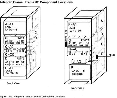
Adapter Frame, Frame 02 Component Locations
,LA...."._C
A
:::
1
::::::::::::::~·7S····::::·~·r···;]
LAB 2
LA 09-16
E-A1
CAB2
CA 09-16
Front
View
F-A1
LA83
p
LA 17-24
T
E~--~~--~~~I.
R
;::::::r··l
cl
~===========:;1::::;l.::
..
1;.·:~;~j
PTERF====~:::::::::::=~~
... '
...,.~...
: M f-~====~..,;I::':F~·:;:::::::::;:.:
CA
09-16
Tailgate
Rear View
....
II .... ··· ....
Jo.j··
Figure 1-5. Adapter Frame, Frame 02 Component Locations
A Line adapter board (LA 09 to 16) F Line adapter board (LA 17 to 24)
See Chapter 4, "Transmission Subsystem See Chapter 4, "Transmission Subsystem (TSS)" on page 4-1. (TSS)" on page 4-1.
B
PS type 4, up to four PS, one PS for two LAs G PS type 4, up to four PS, one PS for two LAs See" PS Type 4 Frame 02 Connection See" PS Type 4 Frame 02 Connection Layout" on page 10-20. Layout" on page 10-20.C AC and DC distribution
H
AC and DC distributionSee page YZ511. See page YZ512.
0 PS type 3, up to four PS, one PS for two CAs J Auxiliary power box
See" PS Type 3 Frame 02 Connection See" Auxiliary Power Box Frame 02 Layout" on page 10-17. (02J-AO)" on page 10-7.
E Channel adapter board (CAs 09 to 16) K Channel adapters 09 to 16 tail gate
See Chapter 7, "Channel Adapter (CA)" on See Chapter 7,. "Channel Adapter (CA)" on
page 7-1. page 7-1.
[image:33.612.48.504.64.444.2]Adapter Frame, Frame 03 Component Locations
Rear View
Figure 1-6. Adapter Frame, Frame 03 Component Locations
F Line adapter board (LA 25 to 32)
See Chapter 4, "Transmission Subsystem (TSS)" on page 4-1.
G PS type 4, up to four PS, one PS for two LAs See" PS Type 4 Frame 03 Connection Layout" on page 10-21.
H AC and DC distribution See page YZ513.
J Auxiliary power box
See "Auxiliary Power Box Frame 03 (03J-AO)" on page 10-7.
Line Frame, Frame 04 Component Locations
1.:::::"1'f/>:·
~---t..
i.l.
E
.,.::::~
B-
8-B1
A1
PSTY5
Lines
or
256-319
PSTY7
1032
8-82
C-AO
P 1020-21
T
D-
D-B1
~
A1
STY5
Lines
or
PSlY7
ID3
128-191
D-82
Front View
G
... 1
.... //
Figure 1-7. Line Fram~, Frame 04 Component Locations
A AC distribution
See" AC-DC Distribution (04A-AO, 05A-AO, 06A-AO)" on page 10-8.
B LlC unit (from line 256 to line 319 for LlCs
1-4, or line 256 to line 287 for LlCs 5-6), See Chapter 4, "Transmission Subsystem (TSS)" on page 4-1,
or "PS Type 5 Frame 04 Connection Layout" on page 10-25 for PS type 5 details,
or "PS Type 7 Frame 04 Connection Layout" on page 10-32 for PS type 7 details.
C Fan for LlC unit
See "PS Type 5 Frame 04 Connection Layout" on page 10-25, or "PS Type 7 Frame 04 Connection Layout" on page 10-32 for details.
o
LlC unit (from line 128 to line 191 for LlCs1-4, or line 128 to line 159 for LlCs 5-6) See Chapter 4, "Transmission Subsystem (TSS)" on page 4-1,
or" PS Type 5 Frame 04 Connection Layout" on page 10-25 for PS type 5 details,
1-16
IBM 3745 Maintenance Information Reference (MIR)E-
E-B1
A1
PSTY5
Lines
or
320-38
PSTY7
1033
E-82
F-AO
P 1022-23
8
D
T
E
G-
G-B1
R
A1
SlY5
Lines
or
192-255
PSlY7
ID31
G-82
Rear View
.~
... ....or "PS Type 7 Frame 04 Connection Layout" on page 10-32 for PS type 7 details.
E LlC unit (from line 320 to line 383 for LlCs
1-4, or line 320 to line 351 for LlCs 5-6) See Chapter 4, "Transmission Subsystem (TSS)" on page 4-1.
or "PS Type 5 Frame 04 Connection Layout" on page 10-25 for PS type 5 details,
or "PS Type 7 Frame 04 Connection Layout" on page 10-32 for PS type 7 details.
F Fan for LlC unit
See" PS Type 5 Frame 04 Connection Layout" on page 10-25, or "PS Type 7 Frame 04 Connection Layout" on page 10-32 for details.
G LlC unit (from line 192 to line 255 for LlCs
1-4, or line 192 to line 223 for LlCs 5-6) See Chapter 4, "Transmission Subsystem (TSS)" on page 4-1,
or "PS Type 5 Frame 04 Connection Layout" on page 10-25 for PS type 5 details,
Line Frame, Frame 05 Component Locations
B-
8-B1
E
A1
PSTY5
Linesor
512-575
PSTY7
1036
B-B2
C-AO
P ID24-25
T
0-
O-B1
E
A1
R
G
.... /).1. ....
STY5
Lines384-447
Front View
Figure 1-8. Line Frame, Frame 05 Component Locations
A AC distribution
See" AC-DC Distribution (04A-AO, 05A-AO, 06A-AO)" on page 10-8.
B L1C unit (from line 512 to line 575 for LlCs 1-4, or line 512 to line 543 for L1Cs 5-6) See Chapter 4, "Transmission Subsystem (TSS)" on page 4-1,
or "PS Type 5 Frame 05 Connection Layout" on page 10-26 for PS type 5 details,
or "PS Type 7 Frame 05 Connection Layout" on page 10-33 for PS type 7 details.
C Fan for LlC unit
See "PS Type 5 Frame 05 Connection Layout" on page 10-26, or "PS Type 7 Frame 05 Connection Layout" on page 10-33 for details.
D L1C unit (from line 384 to line 447 for LlCs 1-4, or line 384 to line 415 for L1Cs 5-6) See Chapter 4, "Transmission Subsystem (TSS)" on page 4-1,
or "PS Type 5 Frame 05 Connection Layout" on page 10-26 for PS type 5 details,
E-
E-B1
B
A1
PSTY5
Lines or576-639
PSTY7
1037
E-82
F-AO
p
ID26-27
T
G-
G-B1
~
Al
PSTY5
Lines·:>::··1
D I
448-511
... ...1 .. / / ....
Rear View
or "PS Type 7 Frame 05 Connection Layout" on page 10-33 for PS type 7 details.
E L1C unit (from line 576 to line 639 for LlCs 1-4, or line 576 to line 607 for LlCs 5-6) See Chapter 4, "Transmission Subsystem (TSS)" on page 4-1.
or "PS Type 5 Frame 05 Connection Layout" on page 10-26 for PS type 5 details,
or "PS Type 7 Frame 05 Connection Layout" on page 10-33 for PS type 7 details.
F Fan for LlC unit
See "PS Type 5 Frame 05 Connection Layout" on page 10-26, or "PS Type 7 Frame 05 Connection Layout" on page 10-33 for details.
G
Lie
unit (from line 448 to line 511 for LlCs 1-4, or line 448 to line 479 for LlCs 5-6) See Chapter 4, "Transmission Subsystem (TSS)" on page 4-1,or "PS Type 5 Frame 05 Connection Layout" on page 10-26 for PS type 5 details,
or "PS Type 7 Frame 05 Connection Layout" on page 10-33 for PS type 7 details.
Line Frame, Frame 06 Component Locations
8-
8-B1
A1
PSTY5
Linesor
768-831
PSTY7
1040
8-B2
C-AO
P 1028-29
T
0-
O-B1
~
A1
S1Y5
Linesor
PSTY7
103640-703
0-82
Front View
...
··:::·~··::·:::·l
E
·:::''::'::1
G
... )
... .
Figure 1-9. Line Frame, Frame 06 Component Locations
A AC distribution
See" AC-DC Distribution (04A-AO, 05A-AO, 06A-AO)" on page 10-8.
B LlC unit (from line 768 to line 831 for LlCs 1-4, or line 768 to line 799 for LlCs 5-6) See Chapter 4, "Transmission Subsystem (TSS)" on page 4-1,
or "PS Type 5 Frame 06 Connection Layout" on page 10-26 for PS type 5 details,
or "PS Type 7 Frame 06 Connection Layout" on page 10-33 for PS type 7 details.
C Fan for LlC unit
See" PS Type 5 Frame 06 Connection Layout" on page 10-26, or "PS Type 7 Frame 06 Connection Layout" on page 10-33 for details.
o
LlC unit (from line 640 to line 703 for LlCs1-4, or line 640 to line 671 for LlCs 5-6) See Chapter 4, "Transmission Subsystem (TSS)" on page 4-1,
or "PS Type 5 Frame 06 Connection Layout" on page 10-26 for PS type 5 details,
1-18
IBM 3745 Maintenance Information Reference (MIR). J - - -_ _ _
--tt:::~.:r>:::'l
E-
E-B1
A1
PSTY5
or
Lines832-89
PSTY7
1041
E-B2
F-AO
P
1030-31T
G-
G-B1
E
A1
R
S1Y5
or
PSTY7
ID39Rear
'. '. ... :>:D
... / ... .1./
or "PS Type 7 Frame 06 Connection Layout" on page 10-33 for PS type 7 details.
E LlC unit (from line 832 to line 895 for LlCs
1-4, or line 832 to line 863 for LlCs 5-6) See Chapter 4, "Transmission Subsystem (TSS)" on page 4-1.
or "PS Type 5 Frame 06 Connection Layout" on page 10-26 for PS type 5 details,
or "PS Type 7 Frame 06 Connection Layout" on page 10-33 for PS type 7 details.
F Fan for LlC unit
See" PS Type 5 Frame 06 Connection Layout" on page 10-26, or "PS Type 7 Frame 06 Connection Layout" on page 10-33 for details.
G LlC unit (from line 704 to line 767 for LlCs
1-4, or line 704 to line 735 for LlCs 5-6) See Chapter 4, "Transmission Subsystem (TSS)" on page 4-1,
or "PS Type 5 Frame 06 Connection Layout" on page 10-26 for PS type 5 details,
IBM 3745 Programming Support
The 3745 operates under the control of IBM licensed programs:
• Controller-resident programs, and • Host-resident programs.
For details on these programs, refer to the publication mentioned in Appendix C
of the 3745 Introduction, GA33-0092.
Controller-Resident Programs
Network Control Program
The NCP provides major capabilities for SNA networks with SDLC. However,
existing start~stop and binary synchronous networks can be migrated to the
3745.
For start-stop protocols, the NCP supports a variety of transmission codes
including ASCII, EBCDIC, EBCD, BCD, and correspondence code, for which it provides translation to and from EBCDIC. For the BSC protocol, support and translation are performed by the communication scanners.
ACF/NCP a110ws the controller to meet the demands of an ever-expanding network. It works with the host access method to control networks, from the simplest single-domain network with a single controller, to complex
multiple-domain networks using advanced communications function networking, in
accordance with the concepts of SNA.
NCP supports Internet Protocol (IP) using the ESS and also enveloped in SNA for transport over wide area networks.
Partitioned Emulation Program
Licensed Program
Partitioned emulation programming (PEP) is a feature of the NCP. PEP lets the NCP operate certain lines in network control mode while operating others under EP control mode.
PEP can run only in a channel-attached controller. One subchannel address is required per line. Channel attachment must be byte-multiplex.
The partitioned emulation program emulates most of the functions of the IBM 2701 Data Adapter Unit, 2702 Transmission Control Unit or 2703 Transmission Control Unit and can communicate with various access methods running in the host. Most programs written for these machines can operate in the 3745
without modification. However, programs that involve timing or special
hard-ware considerations may have to be changed.
The following licensed programs can also reside in the 3745 together with the NCP:
• Network Terminal Option (NTO), which provides SNA protocol enveloping of the start-stop data stream for NCP-attached ASCII devices.
• X.25 NCP Packet Switching Interface (NPSI), for connections over X.25 NCP packet-switched networks.
• X.25 SNA Interconnection (XI) provides an X.25 DCE interface at the 3745 which is part of the SNA network. The SNA network can be used as a transport network for data exchange between two X.25-compatible DTEs attached to a 3745 node operating with XI.
Host-Resident Programs
System Program Support
NetView
The host-resident programs that support the 3745 are:
• ACF/System Support Programs (ACF/SSP).
The 3745 running under NCP/PEP is supported by ACF/SSP in a host. This program is used to generate control program load modules and load them in controller storage. It also allows dumping the controller storage, and transferring disk files to the hosts, including control program dump.
• Access methods located in one or more hosts:
ACF/NCP communicates with on.e or several hosts through:
- Virtual Telecommunications Access Method (VTAM*)
PEP communicates with different access methods in the host processor:
- Basic Telecommunication Access Method (BTAM), - BTAM Extended Support (BTAM-ES).
• Network Management Product (NetView).
NetView is an IBM licensed program used to monitor a network, manage it, and diagnose its problems.
NetView consists of the following components:
• Command facility: NCCF • Session monitor: NLDM • Hardware monitor: NPDA • Status monitor: VCNA • Help facility: NMPF • Browse facility
As a cohesive set of SNA host network management services, NetView offers improvements:
- Consistency and usability in its support for network management, -Easy installation procedure,
- Link between components and functions, - Device support,
- Operator usability.
Network Performance Monitor
The network performance monitor aids network support personnel in managing
controller networks. It collects data in the host and NCP to identify traffic
condi-tions.
The 3745 also supports the Line Problem Determination Application (LPDA *).
Generating and Loading the Control Program
ACF/SSP is used in the host to generate the control program and load it into controller storage. The control program for the controller is generated from standard program modules of the NCP library using the SYSGEN procedure. The control program must reflect the required controller configuration. Several control programs can be generated to handle different subsets of lines attached to the same controller.
The twin CCU configuration implies generating and loading two distinct NCP twins in dual. For the twin in standby mode configuration, the switching capa-bility transfers the control of the adapters of the failing CCU to the standby CCU.
When in twin backup configuration both NCPs must be able to control critical parts of the whole network.
At the initial loading of the control program, the NCP load module can be saved on the disk. This will allow initialization of the CCU from the controller disk. The host operator can also define the stand-alone IPL at any IPL operation.
VTAM and MOSS have been modified to allow new keywords. These new keywords inform MOSS to perform specific actions:
• Save load module to disk.
• Load NCP from disk after an NCP abend or power On. • Dump NCP to disk after an abend.
VTAM also has·a 'MOSS Assist Command'. VTAM can tell MOSS to load from disk.
The dump capability of MOSS allows dump transfer to the host.
Migration/Coexistence
The 3745 running under ACF/NCP can coexist with other IBM communication controllers.
The NCP with the PEP feature permits migration from the 2701, 2702, 2703, and
3704/3705/3720/3725/EP controllers.
The 3745 offers a path for conversion from existing systems and for continuing growth. A system designed with a 3725 may be transferred to the 3745 after modification and regeneration of the control program. The control program generation deck that was used in the 3725 program generation can be used with some modifications to the definition statements (assuming that the con-troller has the same line configuration).
Using the 3745 Library for Service
Remote Service From Hardware Central Service (HCS)
3745
BSC
2400 bps
Switched
Network
Documentation used by the PTCE:
Problem
Determination
Guide
(PDG)
- Connection
and
Integration
(CIG)
Maintenance
Informatiol1
Procedures
(MIP)
y,Z
Pages
RETAIN
System
Service
Functions
(SF)
Documentation used by the PSTCE: Same as PTCE, plus:
Maintenance
Information
Reference
(MI R)
Diagnostic
Descriptions
(DO)
1-22
IBM 3745 Maintenance Information Reference (MIR)External
Cable
Reference
(ECR)
RSF
Console
Service
Master Index
On Site Service
3745
local
Console
Documentation used by the PTCE:
Problem
Determination
Guide
(PO Guide)
YZ
Pages
Maintenance
Information
Procedures
(MIP)
CA OlT
Gui de .
(CAOLT)
Service
Functions
(SF)
Parts
Catalog
(PC)
Connection
and
Integration
(CIG)
Documentation used by the PSTCE: Same as PTCE, plus:
Maintenance
Information
Reference
(MIR)
Diagnostic
Descriptions
(DO)
External
Cable
Reference
(ECR)
Service
Master Index
(SMI)
Preventive Maintenance
Air filters and the battery are replaced by maintenance personnel.
An alert notifies the customer for air filters and battery replacement, and pro-vides the CE with a reference code.
The Maintenance Information Procedures, Chapter 5 "IBM 3745 FRU Exchange" guides the maintenance personnel for replacement procedures.
Maintenance Philosophy
See Maintenance Information Procedures, Chapter 1 "Introducing the IBM 3745 Communication Controller".
Maintenance Aids
Tools and Test Equipment
See Maintenance Information Procedures, Chapter 1 "Introducing the IBM 3745 Communication Controller".
t .
Chapter 2. Central Control Unit (CCU)
The CCU in 3745 Data Flow
General Description . . . . Data Flow . . . . Packaging . . . . Functional Description . . . . Program Levels . . . . Interrupts . . . . Instruction Set . . . . CCU Environment . . . .
CCU Subsystem POR . . . . Main Storage . . . .
Storage Environment . . . . Storage Control/Direct Memory Access (SCTLJDMA)
CCU to/from Storage . . . . High-Speed Buffer (HSB or CACHE) . . . . Storage Protection . . . . CCU Timers . . . . CCU to/from Adapters (CA-LA) . . . .
IOC Control Logic . . . . IOC Data Flow . . . . Registers . . . . Hardware Registers . . . . CCU to/from MOSS . . . .
2-2 2-3
2-3
2-3 2-4 2-4 2-5
2-9
2-12 2-13 2-14 2-14 2-15
2-19
2-19 2-21 2-22 2-23 2-23 2-23 2-24 2-44 2-46 CCU Diagnostics . . . 2-47 CCU Error Handling . . . 2-47 CCU Error Detection . . . 2-50 Problem Isolation Procedure for 210-to-410 or 310-to-610 Model Upgrade . 2-55 STEP 1 . . . 2-56 STEP 2 . . . 2-56 STEP 3 . . . . . . . 2-56 STEP 4
STEP 5 STEP 6
© Copyright IBM Corp. 1988, 1991
2-58 2-58
2-59
The CCU in 3745 Data Flow
on
Operator Console: Local, Remote, RSF
Figure 2-1. The CCU in 3745 Data Flow
General Description
One or two CCUs can be present on the 3745:
• The 3745 Model 210 or 310 is equipped with one CCU.
• The 3745 Model 410 or 610 is equipped with two CCUs.
Data Flow
4, or 8MB
(lor 2 cards)
B
STO
STO
1
D~1A
SCTl
(1 card)
1
Cache
(TCM or PUC card)
(High-Speed
Buffer
SCTl
--.,.
Osci 11 ator
CCU
(TCM only)
M10C
III• to MOSS
Power
--.,.
Supplies
1OC1
1OC2
1 1
[OMA
SWitChl
roc
Switch
Packaging
See pages YZ032 for TCM and YZ022 for PUC for locations.
The CSS includes the following components:
• Processor Unit (TCM or PUC card) • Storage Basic Card (STO)
• Storage Expansion Card (STO) • Storage Control Card (SCTLlDMA).
Functional Description
Program Levels
The central control unit (CCU) is an interrupt-driven processor with a stored program (called the 'control program' in this manual) that controls the data transfers on the channel and transmission interfaces.
The CCU:
• Executes the machine instruction set (CCU cycle = 75 ns for TCM or 56 ns for PUC). to perform arithmetic or logical operations, exchange data between main storage and the working registers, and also between the local store and the work registers.
Data transit between the CCU and main storage is achieved via a high-speed buffer (cache) under the control of the SCTl logic.
Data can also transit directly between main storage and high-speed adapters via the 'Direct Memory Access' (DMA) logic.
• Communicates with adapters through the IOC logic in PIO or AIO mode:
PIO mode: The exchange operation is initiated by IOH/IOHI instructions in the CCU.
AIO mode: The operation uses cycle steals for data exchange between adapters and main storage without control program intervention.
Two buses: IOC1 and IOC2 give access to the adapters' environment through the IOC switch.
• Communicates with the MOSS through the MOSS IOC. The operations per-formed can be direct or indirect (MIOH/MIOHI). MOSS uses the CCU level scan sensitive design (lSSD) to read or write any CCU discrete latch.
The controller hardware has five operational program levels:
.• Program level 1
This is the highest priority program level. Interrupt requests assigned to level 1 include all critical check conditions such as CCU checks, program checks, addressing exceptions, and adapter checks. Initial Program load (IPl) and address compare interrupts are also handled at this level.
• Program level 2
Normal operational interrupt requests from the communication adapters are assigned to this program level and certain program controlled interrupts (PCls) are also assigned to this level.
• Program level 3
Normal operational interrupt requests from the channel adapters, interval timers and program-controlled interrupt 3 '(PCI) requests and panel inter-rupts are assigned to this level.
• Program level 4
Certain program-controlled interrupt (PCI) requests and the supervisor call request (generated when the exit instruction is executed at program level 5), and MOSS request service and request response are assigned to this interrupt program level. This level is the lowest priority interrupt level.
• Program level 5
This level is the lowest priority level and is normally active when none of the other four levels requires program cycles.
Masking Program Level Priorities
Interrupts
Programs at levels 1, 2, 3, or 4 can mask all interrupt requests for program levels 2, 3, or 4 and can mask adapter interrupt requests for ievel 1. Moreover program execution in level 5 can be masked.
The normal operational priority structure can be changed by output instructions X'7E' and X7F' (set/reset mask register).
When the mask is set for one or more of program levels 2, 3, or 4, interrupt requests for those levels will not cause an interrupt. When the mask is set for program level 1, requests by adapters for level 1 will not cause an interrupt though any other request will be honored.
When the mask for level 5 is set, the use of machine cycles for program exe-cution in level 5 is prevented. Thus, level 5 program exeexe-cution is masked. In this case, when no program is executing in levels 1, 2, 3, or 4, the CCU enters the WAIT state and no program executes.
To selectively mask one or more program levels, one of the active general reg-isters is loaded with the bits corresponding to those program levels to be masked. Output instruction X'7E' (set mask register) is then executed using the general register as input to the mask register. To selectively unmask one or more program levels, the same procedure is followed except that the output X'7F' (reset mask register) instruction is executed.
The communication controller operates in response to requests from either the control program or the hardware. Since these requests may have varying degrees of urgency, a priority system is used. Each program, CCU and adapter request, is assigned a particular priority level. A request for use of the con-troller by the control program or hardware functions is called an interrupt request.
Interrupt Mechanism
The interrupt mechanism determines when an interrupt can be handled. If the interrupt request is to be allowed, the change from the active program level to the interrupting program level takes place immediately after completion of the current instruction. If several interrupt requests having different priorities are present at the same time, the one with the highest priority obtains use of the controller. When an interrupt request is granted use of the controller, it can be interrupted in that use by another request having a higher priority.
When an interrupt occurs, instruction execution at the lower priority program level is suspended until instruction execution is completed at the higher priority level. An interrupt to a specific program level prevents future interrupt
requests assigned to either that level or to a lower priority program level from causing another interrupt until the servicing of the first interrupt is complete.
Interrupt Request Determination
The priority of simultaneous interrupt requests assigned to the same interrupt program level is resolved by the order in which the program tests the set/reset condition of the CCU and· adapter interrupt request latches.
Interrupt requests from the CCU and the adapters are grouped together
according to their source for ease of identification. The set/reset condition of a specific interrupt request latch can be determined by checking the interrupt request group to which it is assigned. Input X'77' indicates the non-level 1 interrupt requests that are set by the adapters. Input X'7F' indicates the non-level 1 interrupt requests that are set by CCU or program. Input X'7E' indicates all level 1 requests. These inputs load the contents of the appropriate interrupt request group into an active general register. The program may then test the general register to identify the request.
Setting/Resetting Interrupt Requests
A particular interrupt request latch can be set as a result of a hardware-detected condition or, in some cases, by the program through the execution of an output instruction. The latch can be reset by one of several output
instructions, depending upon the specific interrupt request. The procedures for setting and resetting individual adapter interrupt requests are described in the adapter sections.
For special service requests, program levels 1, 2, 3, and 4 may issue a
program-controlled interrupt (PCI) request to program levels 2, 3, and 4. Output instructions X'7B' (set PCI L2), X'7C' (set PCI level 3), and X'7D' (set PCI level 4) set the PCI interrupt requests. Certain bits in output X'77' (miscellaneous control) reset the PCI requests and other CCU interrupt requests such as the interval timer level 3 request and the SVC level 4 request. If any bits are ON in registers 77, 7E, 7F, a request for a particular program level is active and must be reset or masked before the program can execute in a lower level. The fol-lowing example illustrates the interrupt mechanism.