356
Maximum Power Point Tracking Techniques
for Wind Energy System
Suresh R.Alase1, Sunil S. Jawale2, Prashant R.Borale3, Tushar Nemade4, Samadhan R. Sarode5 1,2,3,4,5
Departmentof Mechanical Engineering
1,2,3,4,5
Pankaj Laddhad Institute of Technology and Management Studies, Buldana Email: [email protected] 1, [email protected]
Abstract-
Wind energy systems are being closely studied because of its benefits as an environmentally friendly and renewable source of energy. Due to the instantaneous changing nature of wind it is desirable to determine the optimal generator speed that ensures maximum energy yield. So, it is essential to include a controller that can track the maximum power point regardless of wind speed. Techniques have been developed to extract maximum power from the wind available, thus ensuring that for any given wind speed, the wind turbine is able to produce power at its peak. An examination of various approaches utilized and an analysis of the strengths and weaknesses of each is presented in this report. Based on simulation results available in the literature, the optimal torque control (OTC) has been found to be the best MPPT method for wind energy systems due to its simplicity. On the other hand, the perturbation and observation (P&O) method is flexible and simple in implementation, but is less efficient and has difficulties determining the optimum step-size.
Index Terms- WECS, Types of wind mill, MPPT techniques.
1. INTRODUCTION
Due to the increasing concern about the environment and the depletion of natural resources such as fossil fuels, much research is now focused on obtaining new environmentally friendly sources of power. To preserve our planet for the future generations, natural renewable sources are being closely studied and harvested for our energy needs. Wind energy is environmentally friendly, inexhaustible, safe, and capable of supplying substantial amounts of power. Wind turbines are controlled to operate only in a specified range of wind speeds bounded by cut-in (Vcut-in) and cut-out (Vcut-out) speeds. Beyond these limits, the turbine should be stopped to protect both the generator and turbine. Figure.1 shows the typical power curve of a wind turbine. From the figure, it can be observed that there are three different operational regions. The first is the low-speed region, where the turbine should be stopped and disconnected from the grid to prevent it from being driven by the generator. The structural over-load, it should be shut down above the cut-out speed. This paper focuses on the moderate-speed region, where the maximum power point tracking (MPPT) algorithm is needed.
Figure 1 Ideal power curve of a wind turbine
National Conference “CONVERGENCE 2016”, 06
th-07
thApril 2016
357 have compared some of the wind MPPT algorithms
particularly for PMSG driven wind turbines. Musunuri and Ginn Iii categorized the available MPPT algorithms into nine groups based on the
specified performance and measurement
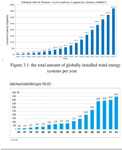
requirements. The authors also reported that there is an increasing trend of MPPT algorithm use among researchers over the past decade. Therefore, recent trends in the proposed wind MPPT technology should be reviewed and compiled. To the best of the current authors’ knowledge, there is limited peer-reviewed literature on the MPPT algorithms for wind energy systems. This review complied and analyzed recently developed MPPT algorithms especially for wind energy systems, particularly the PMSG integrated with boost converter. The fundamentals of the available MPPT techniques for wind energy systems are also reviewed and revised. windmill generator was used to generate electricity, however, it was only in the 1980s that the technology has become mature enough to efficiently and reliably produce electricity. Since then, many wind energy systems have been developed and the technological advances have been phenomenal. Just in last decade, the wind global value of new wind energy plants installed in 2006 alone has reached US $24 billion, and over energy industry has experienced a growth of almost 30 percent each year]. The 70 countries have wind turbine installations. From 1996 to 2014, the total cumulative capacity of global wind power has increased from 6.1 GW to 369.6 GW (See Figure 3.1) In particular, the last two years (2008 and 2009) have been record breaking years for the wind industry. Before 2007, 2006 had the highest ever amount of installations of wind energy systems in a single year, reaching 15 GW (See Figure 3.2). Afterwards, the year 2014 became another historical year as the total cumulative capacity of global wind power increased by 51 GW (27% growth) to reach a final total of 369.6 GW of installed wind power.
.
Figure 3.1: the total amount of globally installed wind energy systems per year
Figure 3.2: the total amount of the newly installed wind energy systems around the world per year
4. WIND ENERGY CONVERSION SYSTEM 4.1 Wind Turbine Technology
The wind turbine is the first and foremost
element of wind power systems. There are two main
types of wind turbines, the horizontal-axis and
vertical-axis turbines.
4.1.1 Horizontal-axis Turbines
Horizontal-axis turbines are primarily
composed of a tower and a nacelle mounted on top of
tower. The generator and gearbox are normally
located in the nacelle. It has a high wind energy
conversion efficiency, self-starting capability, and
access to stronger winds due to its elevation from the
tower. Its disadvantages, on the other hand, include
high installation cost, the need of a strong tower to
support the nacelle and rotor blade, and longer cables
358
Figure 4.1: illustration of a horizontal axis and a vertical axis wind turbine
4.1.2 Vertical-axis Turbines
A vertical axis turbines’ spin axis is
perpendicular to the ground (See Figure 4.1). The
wind turbine is vertically mounted, and its generator
and gearbox is located at its base.
Compared to horizontal-axis turbines, it has
reduced installation cost, and maintenance is easier,
because of the ground level gear box and generator
installation. Another advantage of the vertical axis
turbine is that its operation is independent of wind
direction. The blades and its attachments in vertical
axis turbines are also lower in cost and more rugged
during operation. However, one major drawback of
the vertical wind turbine is that it has low wind
energy conversion efficiency and there are limited
options for speed regulation in high winds. Its
efficiency is around half of the efficiency of
horizontal axis wind turbines. Vertical axis turbines
also have high torque fluctuations with each
revolution, and are not self-starting. Mainly due to
efficiency issue, horizontal wind turbines are
primarily used. Consequently, the wind turbine
considered in this thesis is a horizontal axis turbine.
4.2 Types of Horizontal-Axis Wind Turbines
4.2.1 Pitched Controlled Wind Turbines
Pitch controlled wind turbines change the
orientation of the rotor blades along its longitudinal
axis to control the output power. These turbines have
controllers to check the output power several times
per second, and when the output power reaches a
maximum threshold, an order is sent to the blade
hydraulic pitch mechanism of the turbine to pitch (or
to turn) the rotor slightly out of wind to slow down
the turbine.
4.2.2 Stalled Controlled Wind Turbines
The rotor blades of a stall controlled wind
turbine are bolted onto the hub at a fixed angle. The
blades are aerodynamically designed to slow down
the blades when winds are too strong. The stall
phenomenon caused by turbulence on rotor blade
prevents the lifting force to act on the rotor. The rotor
blades are twisted slightly along the longitudinal axis
so that the rotor blade stalls gradually rather than
suddenly when the wind reaches the turbines’ critical
value.
4.2.3 Active Stall Controlled Wind Turbines
Active stall turbines are very similar to the
pitch controlled turbine because they operate the
same way at low wind speeds. However, once the
machine has reached its rated power, active stall
turbines will turn its blades in the opposite direction
from what a pitch controlled machine would. By
doing this, the blades induces stall on its rotor blades
and consequently waste the excess energy in the wind
to prevent the generator from being overloaded. This
mechanism is usually either realized by hydraulic
systems or electric stepper motors.
5. MPPT TECHNIQUES
Due to the constant variability of wind speed, design of controllers capable of extracting
maximum power from the wind is a constant
challenge, and various techniques have been
developed to obtain higher efficiency from wind
turbines. This should, in the long run, make wind
power an economically viable alternative to
non-renewable energy sources. Although the speed of the
wind turbine could be fixed or variable,
maximization of the extracted energy is achievable
with variable speed wind turbines only. Since these
turbines can change their rotational speed to follow
instantaneous changes in wind speed, they are able to
maintain a constant rotational speed to wind speed
ratio. It can be noted that there is a specific ratio
called the optimum tip speed ratio (TSR) for each
wind turbine for which the extracted power is
maximized. As the wind speed is instantaneously
National Conference “CONVERGENCE 2016”, 06
th-07
thApril 2016
359 variable to maintain the optimal TSR at all times. To
operate in variable-speed conditions, a wind energy
system needs a power electronic converter to convert
the variable-voltage–variable frequency of the
generator into a fixed-voltage–fixed-frequency that is
suitable for the grid. In addition to increasing the
energy capture, variable-speed turbines can be
controlled to reduce the load on the drive-train and
tower structure, leading to potentially longer
installation life. Researchers have discussed the
different possible configurations of power converters
and electrical generators for variable-speed wind
turbine systems. MPPT techniques are divided into
two broad categories:
• Techniques that use known turbine characteristics
• Techniques without knowledge of turbine
characteristics that allow optimization.
5.1. Tip speed ratio (TSR) control
The optimal TSR for a given wind turbine is
constant regardless of wind speed. If TSR remains
constantly at the optimal value, it is guaranteed that
the extracted energy will be maximized. There-fore,
this method seeks to force the energy conversion
system to remain at this point by comparing it with
the actual value and feeding this difference to the
controller. That, in turn, changes the speed of the
generator to reduce this error. The optimal point of
the TSR can be determined experimentally or
theoretically and stored as a reference. Although this
method seems simple as wind speed is directly and
continuously measured, a precise measurement for
wind speed is impossible in reality and increases the
cost of the system. The block diagram of the tip
speed ratio control method is shown in Figure.5.1.3
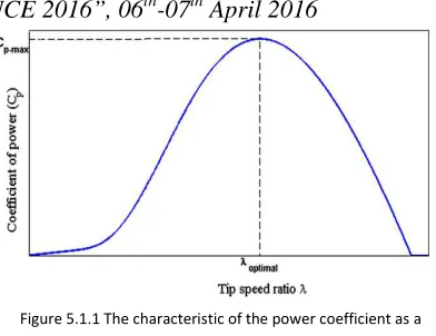
Figure 5.1.1 The characteristic of the power coefficient as a
function of tip speed ratio
The amount of power produced by a wind turbine is
expressed as
where p is air density A is the cross sectional area of
turbine V is wind velocity. The coefficient of power
(cp) is a value dependent on the ratio between the
turbine rotor’s angular velocity, (ωT ) and wind
speed (V). This ratio is known as the Tip speed ratio
(TSR), TSR is given by:
The tip speed of the blade can be calculated as
times R, where is the rotor rotational speed in
radians/second, and R is the rotor radius in meters.
Therefore, we can also write:
360
Figure 5.1.3. The block diagram of the tip speed ratio control 5.2 Optimal torque (OT) control
As mentioned previously, maintaining the operation
of the system at _opt ensures the conversion of
available wind energy into mechanical form. It can be
observed from the block diagram, rep-resented in
Figure 5.2.1, that the principle of this method is to
adjust the PMSG torque according to a maximum
power reference torque of the wind turbine at a given
wind speed. For the turbine power to be determined
as a function of λ and ωm.
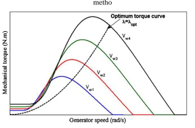
Figure. 5.2.1. The block diagram of optimal torque control MPPT metho
Figure 5.2.2. The torque–speed characteristic curve for a series
of wind speeds
5.3 Power signal feedback (PSF) control
The block diagram of a wind energy system with
power signal feedback (PSF) control is shown in Fig.
8. Unlike the OT control, in this method the reference
optimum power curve of the wind turbine (Figure
5.3.1) should be obtained first from the experimental
results.
Fig. 5.3.1. The block diagram of a wind energy system with the power signal feedback control technique
Fig. 5.3.2. Wind turbine output power and torque characteristics with MPP tracking process
6. CONCLUSION
Maximum Power Point Tracking is an
important technique for efficiently harnessing the
wind power. Selection of the right control strategy is
significant to ensure that the system performs
optimally. Techniques based upon the knowledge of
wind turbine characteristics, that is, Torque, Speed
and Power Signal Feedback based methods provide a
simple way of obtaining maximum wind power
where the manufacturer or by experimentation, the
turbine characteristics have been provided. This
discussed the available MPPT algorithms for wind
National Conference “CONVERGENCE 2016”, 06
th-07
thApril 2016
361
7. REFERENCES
1. Verdornschot M. Modeling and control of wind
turbines using a continuously variable transmission
of Mechanical Engineering; 2009.
2. Bianchi FD, De Battista H, Mantz RJ. Wind
turbine control systems: principles, modelling and
gain scheduling design. Springer-Verlag; 2007
.3. Hui J, Bakhshi A, Jain PK. An adaptive
approximation method for maximum power point
tracking (MPPT) in wind energy systems. AZ:
Phoenix; 2011. p. 2664–9.
4. Mena Lopez HE. Maximum power tracking
control scheme for wind generator systems [Master