Systems Reference Library
File No. 7090-36 Form C28-6383-2
IBM 7090-7040 Direct Couple Operating System
Systems Programmer's Guide
This publication contains information useful to programmers who require a thorough understanding of the IBM 7090-7040 Direct Couple Operating System (DCOS), #7090-PR-161. This system consists of the following parts:
7090/7094 Operating System (IBSYS) 7040/7044 Control Program (DCMUP)
The publication provides descriptions of general DCOS program logic, the format of the DCOS System Library, the Operating System Monitor (DC-IBSYS), and the lnput/Output Executor (DC-IOEX). It also includes instructions for system library preparation and maintenance.
Form C28-6383-2 Page Revised 6/11/65
By TNL N28-0158-0
PREFACE
This publication is primarily intended for systems programmers who are responsible for the maintenance of the 7090-7040 Direct
Couple Operating System (DCOS} and any
modifications to i t at the installation. It may also be of interest to individuals who desire a more thorough understanding of the system.
The reader of this publication is
assumed to be familiar with the contents of the publication IBM 7090-7040 Direct Couple Operating System: Programmer's Guide, Form C28-6382.
Information required by machine opera-tors is contained in the publication IBM
7090-7040 Direct Couple Operatinq Syst~
Operator's Guide, Form C28-6384.
For information on the IBJOB processor, the major subsystem of DCOS, the reader is referred to the following IBM publications:
IBM 7090/7094 IBSYS Operating System:
IBJOB Processor, Form C28-6389
IBM 7090/7094 Proqramming Systems: FOR-TRAN IV Language, Form C28-6390 IBM 7090/7094 Programminq Systems: Macro
Assembly Program (MAP) Language, Form C28-6392
IBM 7090/7094 Programming Systems: COBOL Language, Form C28-6391
IBM 7090/7094 IBSYS Operating System:
IBJOB Processor Debugging Package,
Form C28-6393
Information about the IBM 7040/7044 Data Processing Systems, the IBM 7090/7094/7094
II Data Processing Systems, and for the
Direct Couple feature are given in the
following publications:
Major Revision (March 196~
This edition, Form C28-6383-2, is a major revision of
Form C28-6383-1. This publication amplifies material
pre-viously presented, and, in some cases, provides additional
material. Major changes and additions are concerned with:
examples of system modification, unit control blocks (7040
tape units), the DCOS distribution tape, the system editor (IBEDT), job setup, the $JOB card, and the *REMARK card.
Additions or changes are indicated by a vertical line to
the left of the text; new or revised illustrations are
denoted by the symbol • to the left of the caption.
The following publications are made obsolete by this
revision: C28-6383-1, C28-6383-0,and the Technical
Newslet-ters N28-0146-0 and N28-0144-0.
IBM 7040/7044 Principles of Operation, Form A22-6649
IBM 7090 Principles of Operation, Form A22-6528
IBM 7094 principles of Operation, Form A22-6703
Directly Coupled Processing Units--7040 to 7090/7094; 7040 to 7094/7094 II, Form A22-6803
The Direct Couple Operating System is
designed for five machine configurations:
1. 7090-DC-7040
2. 7094-DC-7040
3. 7094-DC-7044 4. 7094 II-DC-7044 5. 7094 II-DC-7040
Throughout this publication, the terms 7090 and 7040 are used to refer to the 7090, 7094, or 7094 II and to the 7040 or
7044, respectively, as permitted in the
configurations above.
This publication is divided into ten sections. The first section is devoted to the logic flow of the 7040 side of the system. The next three sections are devot-ed to the 7090 side of the system. The fifth section explains the logic used by the 7040 when servicing 7090 input/output
requirements. The sixth section describes
the DCOS Distribution Tape. The seventh
section describes system editing
proce-dures. The eighth and ninth sections deal with system library preparation and
main-tenance. The last section discusses DCOS
unit assignment philosophies.
Copies of this and other IBM publications can be obtained through IBM Branch Offices.
A form for readers' comments appears'at the back of this publication. It may
be mailed directly to IBM. Address any additional comments concerning this
publication to the IBM Corporation, Programming Systems Publications, Department D39, 1271 Avenue of the Americas, New York, NY., 10020.
INTRODUCTION TO DCOS
DCOS Use of Disk/Drum Storage Units
Modes of Operation • • • • The Direct Mode • • • • The Compatibility Mode •
7 7 8
8
8
General Logic Flow 8
The DCOS Commutator 10
The Job Queue Table 10
The Job Description Block 10
Unit Control Blocks (7040 Tape
Uni tS) • • • • • • • • • • • • • • 10
File Control Blocks • • • • • • 10
Channel Information Blocks • • • • • 10 Input/Output File Control Block Base
(IOBASE) • • • • • • • 12
Data Buffer Format • • • 13
Input Service Routine 14
Job Setup 14
Initialization for 7090 Execution 17
Job Breakdown 17
Punch Stage • • • • • 17
Print Stage • • • • • 18
Background Utility Routines 19
7040/7044 Utility Routines • 19
DC-IBSYS MONITOR 21
DC-IBSYS SUPERVISOR • • 22
Initialization Procedures • 22
Basic Supervisor Control Cards 22
$Job Card 22
$EXECUTE Card 22
$ID Card • • 23
Unit Assignment Control Cards • $ASSIGN Card •
$RELEASE Card $RESET Card $SWITCH Card $CARDS Calrd $TAPE Card • •
Tape-Manipulation Control Cards $ENDFILE Card
$REWIND Card $REMOVE Card • •
$UNLOAD Card • • • • • •
Miscellaneous Control Cards $STOP Card • • • • • • •
$IBSYS Card • • • •
DC-IBSYS Supervisor Control Cards • $RESTORE Card
$IBEDT Card
23 23 24 24 24 24 24 24 24 25 25 25 25 25 25 25 25 26
Form C2B-6383-2 Page Revised 6/11/65
By TNL N2B-015B-O
CONTENTS
$UNITS Card • • • • • • • • • • • • • 26
DC-IBSYS NUCLEUS
Communication Region
System Unit Function Table
Unit Availability Table • •
Job Control Communication With Subsystems • • • • • • • • • •
Communication Region Locations
SYSRET, SYSGET, and SYSJOB • • • •
Recognition of DC-IBSYS Supervisor Control Cards by SUbsystems
$IBSYS Card $EXECUTE Card $STOP Card •
$ID Card • • • • •
DIRECT COUPLE INPUT/OUTPUT EXECUTOR • •
Unit Control Blocks •
Word 1 • • • •
Word 2 • • • • • Word 3 • • • • • Word 4
Unit Priority on a Channel
Channel-Priority Location • • • • • Use of Channel-Priority Location Activating a Channel and/or Assigning
Priority • • ~ • • • • • • • • • •
Non-Data Selects • • • • •
Structuring of Input/Output Requests in
Direct Mode • • • •
INPUT/OUTPUT IN THE TWO DCOS MODES
Processing Input/Output Requests
(Direct Mode) • • • • • • • • • •
Processing Input/Output Requests (Compatibili ty Mode)
DISTRIBUTION OF DCOS
Listings
DCOS Distribution Tape File 1 • • • • • File 2
File 3 File 4 Files 5-15
SYSTEM EDITOR (IBEDT) *EDIT Card • • • • •
Form C28-6383-2 Page Revised 6/11/65
By TNL N28-0158-0
Arrangement of DCMUP, DC-IBSYS, IBSYS
Subsystems and the System Editor • • • • 48 *PLACE Card • • • • • • • • • • • • • 48 Maintenance of the System Name and
Loader Tables. • 48
Alteration Cards • • • • • • • • • • 49 Absolute Column-Binary Cards. • 50 Octal Cards • • • • • • • • • • 50 Standard PRESYS Library Record Formats • 50 Maintenance Control Cards • • •
*MODIFY Card. • *REPLACE Card • *INSERT Card. *REMOVE Card. • *AFTER Card • • *DUP Card • • • *REWIND Card. • *CHECK Card • • *REMARK Card. •
Termination of Editing •
Editing Relocatable Records. • • Editing Examples •
Example 1
Example 2 • • •
DCOS PRESYS LIBRARY MAINTENANCE. Preparing a Backup DCOS Distribution
• 51 • 51 • 51
• 52
• .53 • 53 • 53 • 54 • 54 • 54 • 54 • 54
• 55
• 55
• 55
• 57
Tape or PRESYS Library Tape • • • • 57 Changing The System Input/Output
Configurations • • • • • • • • • 7040 Input/Output Configuration Incorporating a User-Designed
Installation Accounting Routine Under • 57 • 58
DC-IBSYS. • • • • • • • • • • • • • • • 61 Designing An Installation
Accounting Routine • • • • • • 61 Incorporating an Accounting Routine
into a Subsystem. • • • • 61 Incorporating IBSYS Subsystems Under
DC-IBSYS. • • • • • • •
Compatibility Mode. • • • • • Direct Mode • • • • • • • • •
• 62 • 62 • 62 Incorporating DCMUP Utilities. • • 63
Arrangement of DCMUP Utility
Programs • • • • • 63
Design of DCMUP Utility Programs. • • 64 Incorporating Non-IBSYS Systems or
Programs. • • • • • • • • • • • • • 64 DCOS OPERATIONAL LIBRARY PREPARATION 67 Role of the DCOS Posteditor • •
Phase I • • Phase II. • •
• • • • • 67 67 67
Respecification of 7040 Disk (Drum)
Environment • • • • • • • 67 Preparation of a New DCSYS from a DCOS
PRESYS Library. • 68
Posteditor Output.
7040 System Name Table. Track Allocation and Module
Definition Table • • • • • Utility Name Table • • • • • Posteditor Output Tape (DCSYS)
Format • • • • • • • • • • • • Posteditor Restrictions and Error
Messages.
DCOS UNIT ASSIGNMENT PROCEDURES • • 7040 File Control Blocks • • • • Assignment of 7040 Tape Units to
7040 File Control Blocks • • • Communication Of 7040 File Control
Block--7090 Unit Control Block Relationship. • • • • • • • • • • IBLDR Unit Assignment Process • • •
Assignment of Secondary Units • Unit Assignment In Other IBSYS
• 69 • 69 • 70 • 70 • 71
• 71 • 73 • 73 • 74
• 74 75 76
Subsystems. • • • • • • • • • • • • 76 Unit Assignment Procedures for
Non-IBSYS Systems/Programs • • Unit Assignment Considerations APPENDIXES •
Appendix A: DCMUP Tables and Control Blocks. • • • • • • • • •
The Job Queue Table • • Job Description Block • DCMUP Track Allocation Maps File Control Block. • • • • Unit Control Blocks (7040 Tape
Uni tS) • • • • • • • • • • Channel Information Block
Appendix B: Procedure for Defining an IOBASE Table • • • • •
Zero Pointers (ZERPTR) Macro-Instruction. ~ • File Control Block Pointers
(FBPTRS) Macro-Instruction Input/Output Unit Configuration
(IOBASE) Macro-Instruction • • $IOBASE Card. • • • • • • • • • Appendix C: DC-IBNUC Communication
78 78 80
80 80 • 80 83 • 83 • 84 • 85
• 86 • 86 • 87 87 • 87
Region Entries. • • • • • • • • • 87 Appendix D: Creation of a DCOS
PRESYS Library from a 7090/7094 IBSYS Operating System Library. • • • 89
Case 1: Preparation on a
Case 2: Preparation on a
7090-7040 Direct Couple System • • • 90
Appendix E: Redundancy Conditions,
Tape Density, Mode, and Parity in
DCOS. • • • • • • 90
Appendix F: DCOS debugging Aids
Program • • • 90
ILLUSTRATIONS
Figure 1. Compatibility Mode.
Figure 2. General Logic Flow Figure 3. DCOS Commutator
Figure 4. 7040 Data Buffer Format Figure 5. Four-Word Setup Entry Figure 6. Communication Region of
DC-IBSYS Nucleus. • . .
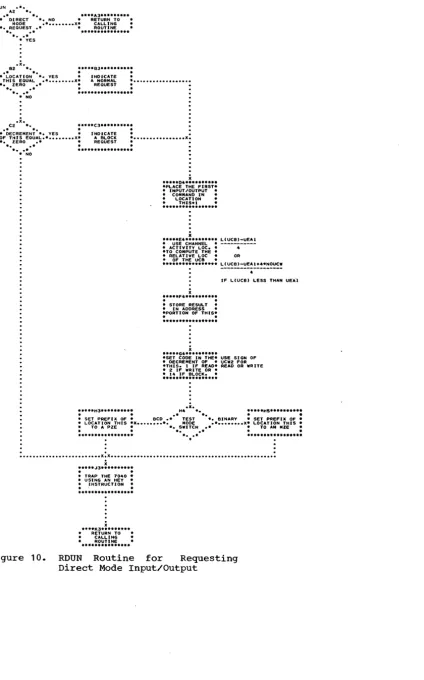
Figure 7. System Unit Function Table. Figure 8. Unit Control Block. . • . Figure 9. DC-IOEX Communication Table Figure 10. RDUN Routine for Requesting
Direct Mode Input/Output • .
Figure 11. Format of THIS and THIS+1 Figure 12. DCSYS Format for Scatter
Load • . . • . • . . • • • •
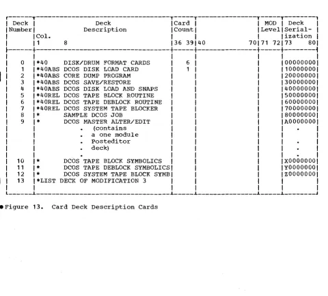
Figure 13. Card Deck Description Cards Figure 14. DCOS PRESYS Library
Figure 15. Three-Phase Editing
Operation . • • . . • • • . • • • Figure 16. Sample Edit with
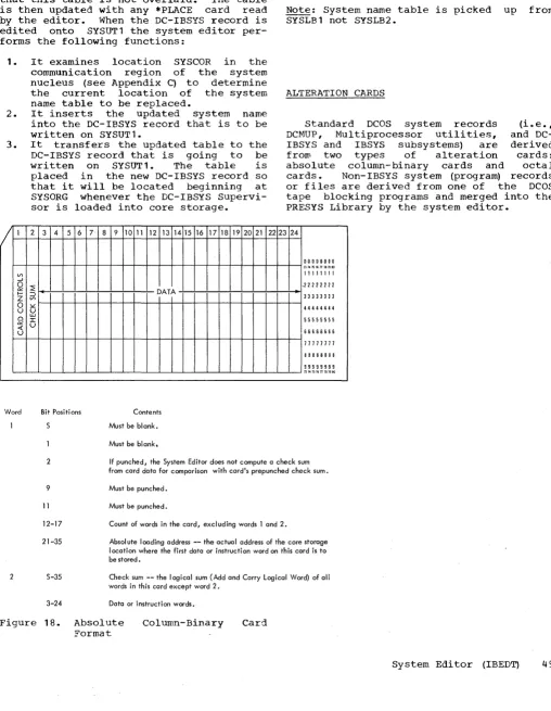
Modifica-tions to DCMUP, DC-IBSYS, and IBMAP Figure 17. DCOS Master Alter/Edit Deck Figure 18. Absolute Column-Binary Card
Format. . • • . • • . . . • • •
Figure 19. Standard PRESYS Library Record Format
Figure 20. Sample Edit Figure 21. Sample Edit 2
Figure 22. Preparing a Backup PRESYS Tape • . • . • . • • • . • • • • • Figure 23. Distributed 7090 Input/
Output Configuration Simulated by DCMUP (IOBASE 0) • • . • . •
Figure 24. Assignment of System Unit Functions . • . . . • . • Figure 25. 7040 Input/Output
Configuration • . • . • • • • • • •
9
11 12 15 16
28 28 31 32
36 37
41 42 43
44
45 46
49
50 55 56
57
58
58
60
DCMUP Patches • • • • • • • • • • • 91 DC-IBSYS Patch Routine • • • • • • • • 91 7040 Core Storage Snapshot Routine
(SNAP) • • • • • • • • • • • • • • • 91
Appendix G: Conversion of IBSYS
Systems to Direct Mode • • • • • • • • • 91
Figure 26. Incorporating an IBSYS Sub-system (Compatibility Mode) • . . . . 62 Figure 27. Sample Job Deck for
Inserting a User Program as a Direct
Mode IBSYS Subsystem • . . . • . • 64
Figure 28. Sample Job Deck for Incor-porating the First Non-IBSYS System
onto a PRESYS Library Tape • . . . 65 Figure 29. Sample Job Deck for
Incor-porating an Additional Non-IBSYS
System onto a PRESYS Tape . . . . 66
Figure 30. Sample Postedit Run 69
Figure 31. Sample Job Deck for
Inserting a New DCSYS (Postedit
Out-put) into a DCOS Distribution Tape • • 69 Figure 32. 7040 System Name Table . . . 70 Figure 33. Track-Allocation and
Module-Definition Module-Definition Table . . . . 70 Figure 34. Utility Name Table. . . . • 71 Figure 35. Posteditor Output: Format
of DCMUP, DC-IBSYS, IBSYS Subsystem, and DCMUP Utility Records • • • • • 71 Figure 36. Posteditor Output: Data
Record Format . • . • • • . • . 72 Figure 37. Relationship of 7090 Unit
Control Blocks to 7040 File Control
Blocks • • . . • . . • . • • • 74
Figure 38. IBLDR Unit Assignment
Under DCOS • • • . . • • . • • • 77
Figure 39. IOBASE1 Unit Configuration 78
Figure 40. Job Description Block 82
Figure 41. File Control Block. • . 83
Figure 42. 7040 Unit Control Block
(Tape Interface) • • . • . • • • • 85
Figure 43. Channel Information Block 86
Figure 44. Deck Setup for Using
Case 2: Preparation on a 7090-7040 Direct Couple System • • • • • • • • 90 Appendix E: Redundancy Conditions,
Tape Density, Mode, and Parity in
DCOS. • • • • • • • • • • • • • 90 Appendix F: DCOS debugging Aids
Program • • • • 90
ILLUSTRATIONS
Figure 1. Compatibility Mode. • • • 9 Figure 2. General Logic Flow • • • • • 11 Figure 3. DCOS Commutator • • • • • • • 12 Figure 4. 7040 Data Buffer Format • • • 15 Figure 5. FOUr-Word Setup Entry. • 16 IFigure 5A. Units Printout . . . 26
Figure 6. Communication Region of
DC-IBSYS Nucleus . • • • • • • • • • • • 28 Figure 7. System Unit Function Table • • 28 Figure 8. Unit Control Block. • • 31 Figure 9. DC-IOEX Communication Table • 32 Figure 10. RDUN Routine for
Requesting Direct Mode Input/Output • • 36 Figure 11. Format of THIS and THIS+1 • • 37 Figure 12. DCSYS Format for Scatter
Load. • • • • • • • • • • • • 41 Figure 13. Card Deck Description Cards • 42 Figure 14. DCOS PRESYS Library. 43 Figure 15. Three-Phase Editing
Operation • • • • • • • • • • . • • 44 Figure 16. Sample Edit with
Modifications to DCMUP, DC-IBSYS, and IBMAP • • • . • • • • • • • • • 45 Figure 17. DCOS Master Alter/Edit Deck. 46 Figure 17. DCOS Master Alter/Edit
Deck (continued) • • • • • • • • . • • • 47 Figure 18. Absolute Column-Binary
Card Format • • . • • • • • • • • • • • 49 Figure 19. Standard PRESYSLibrary
Record Format • • • • • • • Figure 20. Sample Edit 1. • •
Figure 21. Sample Edit 2 • • •
Figure 22. Preparing a Backup PRESYS
• • 50 • • 55 • • 56 Tape. • • • • • • • • • • • • • • • 57 Figure 23. Distributed 7090
Input/Output Configuration Simulated by DCMUP (IOBASE 0) • • • • • • Figure 24. Assignment of System Unit
• 58 Functions • • • • • • • • • • • • 58 Figure 25. 7040 Input/Output
Configuration • • • • • • • • • • 60
Form C28-6383-2 Page Revised 12/7/65 By TNL N28-0175-0 DCMUP Patches • • • • • • • • • • • • 91 DC-IBSYS Patch Routine. • • • U • 8 • 91
7040 Core Storage Snapshot Routine (SNAP) • • • • • • • • • 91 Appendix G: Conversion of IBSYS
Systems to Direct Mode. • • • • • 91
I
APpendix H: GETBUF and PUTBUF AsSystem Macros or Subroutines • • • • • • 92
Figure 25A. Installation Accounting Routine Calling Sequence Parameter Words • • • • • • • • • • .• .. • • Figure 26. Incorporating an IBSYS
sybsystem (Compatibility Mode) • • Figure 27. Sample Job Deck for
Inserting a User Program as a Direct Mode IBSYS Subsystem. • .. • • • • Figure 28. Sample Job Deck for
Incorporating the First Non-IBSYS System onto a PRESYS Library Tape Figure 29. Sample Job Deck for
Incorporating an Additional Non-IBSYS System onto a PRESYS Tape • • • • Figure 30. Sample Postedit Run. • Figure 31. Sample Job Deck for
Inserting a New DCSYS (Postedit
• 61 • 62
• 64
• 65
• 66 • 69
output) into a DCOS Distribution Tape .. 69 Figure 32. 7040 System Name Table • 70 Figure 33. Track-Allocation and
Module-Definition Table • • • • • .. 70 Figure 34. Utility Name Table • •
Figure 35. Posteditor Output: Format of DCMUP, DC-IBSYS, IBSYS Subsystem,
71
and DCMUP Utility Records • • • .. • D • 71 Figure 36. Posteditor Output: Data
Record Format • • • • • • • • • 0 • 0 • 71 Figure 37. Relationship of 7090 Unit
Con-trol Blocks to 7040 File Control Blocks. • • • • • • • • • • • . • • • .. 74 Figure 38. IBLDR Unit Assignment
Under DCOS. 0 • • • • • • • • • • • 77 Figure 39. IOBASE 1 Unit Configuration. 78 Figure 40. Job Description Block • • .. • 82 Figure 41. File Control Block. • • • .. • 83 Figure 42. 7040 Unit Control Block
(Tape Interface) . . . 85 Figure 43. Channel Information Block. • 86 Figure 44. Deck Setup For Using
The IBM 7090 IBJOB Processor is the only
distributed programming system operating
under DCOS control. Any program that is
written in the FORTRAN IV, the COBOL, or the MAP language and that uses the IBJOB Input/Output Control System will operate under DCOS with little or no modification. The 7090 Operating System Monitor (IBSYS)
has been replaced by a 7090 Operating
System Monitor with Direct Couple
capabili-I
ties (DC-IBSYS) and the system editor
(IBEDT) has been modified to operate under
DC-IBSYS.The IBJOB processor has been
modified to communicate, through DC-IBSYS, with the 7040 for input/output processing.
The 7040 control program (DCMUP)
per-forms the preprocessing and postprocessing
of jobs, schedules work for 7090
processing, and performs all input/output
functions for the 7090.
Jobs are prepared for DCOS in much the
same manner as for the IBSYS operating
system. When a job is ready for entry into the system, i t is placed in the IBM 1402 Card Reader. As a job is read in, a job description block is created for job con-trol. The job deck is then written on the disk (dru~ storage unit to await process-ing, and an entry is made in the job queue
table in a position based on the job's
priority. The job description block and
the job queue table are described later in this publication.
When the 7090 requires input/output
activity, the request and the input/output
commands are sent to the 7040 for
execution. In the case of input, the 7040 interprets the request and transmits the specified number of words from a 7040 core storage buffer to the 7090. When the 7090 has an output record ready, the 7040
trans-mits the record to a 7040 core storage
buffer. As the buffers are filled, they
are written on the disk (drum) or a 7040
tape unit. Communication is effected
between the 7040 and the 7090 by traps.
The 7040 interprets input/output
requests and transmits data between its core storage and 7090 core storage under
control of 7090 data channel commands
(IOCP, IORT, etc.). When transmission has been completed, the 7040 transmits flags to the 7090 for such conditions as end of file
and traps the 7090 to signal that the
request has been serviced. The 7090 then handles this trap in the same manner that i t handles a data channel trap in a stand-alone system.
INTRODUCTION TO DCOS
When the 7090 completes a job, i t
signals that it is ready for the next job. The 7040 selects the next job that is ready to be processed by the 7090 and reads its job description block into 7040 core
stor-age. A 7090 initialization program is
transmitted to the 7090. This program
clears 7090 core storage. DC-IBSYS is'then loaded into the 7090 from the disk (drum)
and is given control. For systems that
operate in the direct mode, job processing then proceeds as i t would on a stand~alone 7090 except for processing of input/output
requests. When a DC-IBSYS subsystem job
segment that is to be run in the compat-ibility mode is recognized by the DC-IBSYS
Supervisor (DC-IBSUP), an
enter-compati-bility-mode call is sent to the 7040. The 7040 then loads the desired DC-IBSYS sub-system and gives i t control.
For job segments that do not operate
under DC-IBSYS, the 7090 issues an
enter-compatibility-mode call to the 7040. The method used to load the desired system is ~hen determined by the parameter of the $EXECUTE card. This parameter will be the
word CARDS, the word TAPE, or a system
name. If the parameter is CARDS or TAPE,
pressing of the appropriate 7090 LOAD
button is simulated in the 7090. If the parameter is a system name, the specified system is loaded into the 7090 from the disk (drum) and given control.
When a job has been completed, the 7090 stops, trapping the 7040 so that all input and output files for that job can be closed
and another job initiated for the 7090.
The output of the completed job is then queued for printing and punching. When all postprocessing has been completed, the job is purged from the job queue table and all disk (drum) storage tracks associated with the job are made available to the system for use by subsequent jobs.
DCOS USE OF DISK/DRUM STORAGE UNITS
DCOS contains procedures that provide
dynamic assignment of disk (drum) tracks. The tracks are allocated to the jobs as they are needed and returned to available
status when the job is completed. No
particular job type or data file is res-tricted to any specific number of tracks or modules.
MODES OF OPERATION
The Direct Couple Operating System has
two modes of operation: the direct mode
and the compatibility mode. The primary
difference between the two modes is the
method used for processing 7090
input/output requirements. The direct mode
is the faster of the two in that
input/output requests are serviced with a
minimum amount of interpretation and a
mlnlmum number of multiprocessor traps.
The 7040 contains a program that services 7090 input/output requests. The 7040 con-trol program also schedules jobs for the 7090 and handles preprocessing and
postpro-cessing. Control of the entire system
resides in the 7040 commutator.
THE DIRECT MODE
The qirect mode is the normal DCOS mode of operation. In this mode, DCOS ignores the existence of 7090 data channels. DC-IBSYS and DC-IOEX in the 7090 handle all input/output by treating the DC channel as a data channel. The input/output executor
(DC-IOEX) structures an input/output
request and traps the 7040, the 7040 then transmits the request to its core storage,
and the 7090 continues processing. The
7040 interprets the request, processes it, and traps the 7090. DC-IOEX then processes the trap as i t would a normal data channel
trap. The 7090 does not execute any
input/output instructions or commands.
THE COMPATIBILITY MODE
The compatibility mode is provided for the execution of systems and object pro-grams that do not utilize the direct mode
input/output conventions. When the 7090
DC-IBSYS determines from a $EXECUTE card
that one of these systems is specified, the
compatibility mode must be entered. The
logic of the compatibility mode is shown in
Figure 1. However, in the compatibility
mode, each time an input/output instruction is encountered in the 7090, the 7090 halts, trapping the 7040. The 7040 then transmits the input/output instruction to its core storage and interprets i t before restarting
the 7090. This multiple trapping and
interpretation while the 7090 is idle
results in slower input/output processing when operating in the compatibility mode.
To enter the compatibility mode, the
7090 sets up two communication cells (THIS and THIS+1). An input/output call is set
8
up with 00009 in the decrement of THIS and the name of the system to be loaded in
THIS+1. The 7090 then executes an HEY
(BTTE) instruction, which causes the 7040 to trap and places the 7090 DC-IBSYS in a
waiting loop. The input/output call is
decoded by the 7040 trap routine WHAT,
which then transfers control to routine HIP. In the HIP routine, an Enter Halt on Input/Output Primary Mode (EH~ instruction is executed, putting the system in compat-ibility mode. The name of the system to be loaded is then examined.
If the system to be loaded resides on
disk, the system name is given on the
$EXECUTE card. If the system is to be
loaded from cards or tape, the word CARDS or TAPE is on the $EXECUTE card instead of the system name.
If the $EXECUTE card parameter is CARDS or ·TAPE, the 7040 executes an FMT (Force Multiprocess Trap) instruction, causing the 7090 to trap to a routine that breaks the
waiting loop. The 7090 then transfers
control to a routine that determines wheth-er the system is to be loaded from tape or cards. This routine simulates pressing of the appropriate load button and the system is loaded in the compatibility mode.
If the $EXECUTE card parameter is not CARDS or ~APE, the system must have been edited onto the disk. If the system is a DC-IBSYS subsystem, i t is scatter-loaded by the 7040. At the completion of the load, the 7040 posting routine (CPOST) starts the 7090. If the system is on the disk but is not a DC-IBSYS subsystem, i t is loaded by the 7040 as a data file using a normal read routine.
GENERAL LOGIC FLOW
Figure 2 shows the general logic flow of
DCOS. The figure shows the sequence of
operations performed while processing one
job. However, the reader should keep in
mind that many jobs are being processed
simultaneously. A job may be staged for
processing by a routine but may have to wait until the routine has completed proc-essing a previous job.
Job flow is controlled in the 7040 by
the job queue table and the DCOS
commutator. When the commutator gives con-trol to a routine, the routine searches the
job queue table for jobs that it must
process. If the routine does not locate
work before returning control to the cornrr,u-tator. For example, the print routine sets up one line of print, signals the 1403 to start, and returns control to the commuta-tor. The next time the print routine is entered, i t sets another print image, sig-nals the 14.03, and exits. In 'this way the
7040 is not tied up waiting for
input/output units to complete their opera-tion.
The following descriptions are concerned with 7040 tables, blocks, and routines used
to process jobs. A detailed figure and
explanations of the contents of the tables and blocks are included in Appendix A.
Figure 1.
RDS.WRS ACH.LCH.*.
: • • • • "1 • • • • • • • •
*:
A2 *. • •••• "3 • • • • • • • • • •.* *. .. GET THE ..
• SET THE .* IS THE *. YES .. INPUT/OUTPUT ..
• Rt:.AD/WRlTE -.SELECT SWITCH • • • • • • • • • • X.COMMAND AND
THE-: SWITCH • ". S E T . " • FILE CONTROL .. . . . • BLOCK POINTER •
...
* •• * ... .X
····*61··*···
• GET THE FILE • .. CONTROL BLOCK • • POINTER FOR THE. • SELECT EO •
:.*.*.~~!! •••••• :
x
: . . . Cl • • • • • • • • • :
SI:T THE SELECT SWITCH
*
...
ROC. •
SPR.SPU X : ••• *01*.*.* •••• :
.. NO
x : • • • • 82 • • • • • • • • • :
.. SET ..
.. INPUT/OUTPUT • • • • • • •
: CHEC>( IN 7090 :
...
START .. •
.. 7~~~ : • • • • • • • • • • • • • • • • • • • • • • • • • • • • • • X.
•••••••••••••••• *
TCO TCN
· .. ···El··· ... ··
• • • • *E2*·***···• START THE 7090 .. .. START ..
.. THE 7090 AT • • THE NEXT • • SEQUENTIAL • • I NSTRUCTI ON •
...
.AT THe: LOCAT ION- •
• SPECIFIED BY . . . X.
* THE TESTING • .. INSTRUCTION •
••••••• * •••••••••
.
.
• • • • • • • • • • • • • • • • • • • • • • • • • • • • • • • • • • • • • • • X.
TRC.TEF.·.
F l . . • •••• F2 • • • • • • • • • • • -IS THE •• • START •
•• INDICATOR •• NO • THE 7090 AT •
•• BEING TESTED • • • • • • • • • • X. THE NEXT * •••• x.
•• O N . . • SEQUENTIAL •
*. .•• • INSTRUCTION •
•• • * *._* ••• * •••••••••
.. YES
x
: • • • • Gl . . . : :;;::~2;~:.;~:~.:
• R E S E T . "AT THE LOCATION" •
THE • • • • • • • • • X .. SPECIFIED BY ••••• X.
INQICATOR" * THE TESTING •
: •••••••• * •••••• : :*.!~:!:~~!!~: •• :
BTT.ETT ....
HI ... • •• *.H2 ... . • *IS THE *. .CAUSE THE 7090 • • " INDICATOR •• NO • TO SKIP THE. •
.... BEING TESTED • • • • • • • • • • X. NEXT * •••• X.
•• O N . . • INSTRUCTION •
* . . . ... AND START IT •
* •• * •••••••••••••••••
.. YES
x
: • • • • .Jl." • • •
*.".:
: ••••
.J~;::;" ••*.:
• R E S E T . • THE 7090 A T . •
.. THE . . . X. THE NEXT * •••• X.
INDICATOR" • SEQIJENTIAL ..
... ! : .. ~~~!:~~!!~~ .... :
X
• • • • 83·· • • • • • • •
• GO TO THE • • READ/WR I TE ..
.. •••• :~~!!~~ ...
NOS
····.04.···.····
.SET THE EXIT TO" • THE REQUIRED • • NON-DATA • SELECT •
• •••• :~~!!~~ •••• :
X
·· ... e.··· .. ···
• GET THE FILE • • CONTROL BLOCK .. • POINTER FOR THE • • SELECTED .. .. UNIT ..
...
x
····c.···.···
• EXIT TO .. .NDN-DATA SELECT" •
...
ROUTINE •TRP90
: • • • • 04 • • • • • • • • • :
ENB
: • • • • • 5 • • • • • • • • • :
.. GeT • THE eNABLE
: WORD •
.
... .
.X.
BS ••
..
..
•• IS •• YES
• • IT • • • • • • •• ZERO ••
•.•..• ··1
• NO
RCT X
: •••• cs ••••••••• :
SET THE ENABLE • SWITCH •
...
.X.
05 ••
..
..
.. SET • YES ... IS *. .. TRAP WAITING .x •••••••••• THEAE A TRAP ••
• FOR ENABLE" •• WAITING ••
·
-
-..--...
.
...
.X.
E4 ••
..
.
.
. - IS *. NO ... THE 7090 • • • • • • • ••• ENABLED ••
.. ..
* •••
• YES
• NO
X
···ES.·.···· ...
.START THE 7090 • • AND ENABLE • .NUL TI PROCESSOR.
: TRAPS :
.
... .
F4 .x... X
•• ··IS THIS·· •• NO X ... ,.5 • • • • • • • • • •
*. CHANNEL • • • • • • • • • • X. EXIT .. ... ENABLED ...
....
•.
... .
•.
...
• YES
X
··· .. ·G.···
.. TRANSNIT THE . • • CONDtTION BITS •• .. RESET FLAGS. .. • AND TRAP • • THE 7090 •
...
X
·· ... H.·.···.···.
.. SET THE 7090 • .. TO START • .. AT THE TRAP • .. CELL FOR THI S •
: ••••
~~::=~~•••• :
·
.
• x •••••••••••••••••••••••••••••••••••••
x : . . . . *.1 . . . :
.. START • .. THE
: 7090 •
...
~;~.*Kl •• ** .... **. • •••• KZ ... * .... **... X
: T~~A~~:~~EL : : THES~~~~ A T : x ... K4 . . . ..
: R~~I~~~RS : ••••••••
x:
s~~~E~i~lL : ••.•••••.••••••••.••••••••••••••••X:
EXIT :.. 7090 • • INSTRUCTION • • . . . ..
... • ... *.
Compatibility Mode
Form C28-6383-2
Page Revised 12/7/65 By TNL N28-0175-0
THE DCOS COMMUTATOR
In DCOS, three operations may occur at
the same time: input/output functions,
7040 preprocessing and postprocessing, and data processing in the 7090. These opera-tions are controlled by a section of DCMUP called the commutator. Figure 3 shows the logic of the commutator.
The commutator consists of a series of in-line instructions that act as gates. The~e gates are opened and closed to deter-mine which set of processing routines is to be entered next. The gates are opened and closed by changing their operation codes. A gate is said to be open when its opera-tion code is a Transfer on Index Low or Equal (TXL) and closed when it is a
Trans-Ifer on Index High (TXH). Because index
register zero is specified, the TXL always
transfers control to the desired routine
and control always falls through the TXH to the next gate.
THE JOB QUEUE TABLE
The job queue table is the DCOS work flow supervisor. As each job is read into
the 7040, a one-word entry is made in the
table' that is used during processing to
reflect the job's priority, its present
status, and to provide the module and track address of the job description block for the job. The table is located and main-tained in a 460-word buffer in the 7040. Each time an entry is updated, the entire
table is written on track 2, module 0
(channel B) of the disk.
THE JOB DESCRIPTION BLOCK
Each job in DCOS has a job description block associated with it. These blocks are
created as the jobs are read into the
system. The blocks are saved on the disk and read into the 7040 each time the job enters a new phase of processing. As a job is processed, its job description block is updated to reflect the job's status and the block is rewritten on the disk (drum).
The major portion of a job description
block is reserved for task descriptions.
Each task that must be performed for a job
during processing has a three-word task
description in the job description block
for that job. rhese task descriptions are
10
used to indicate the type of task to be
performed and the track address of the
first block of data associated with the
job. There is a task description for each Ifile written on the disk. Also, at the end of each job description block there is a group of words called the peripheral track
bit map, whose bits represent the disk
t~acks containing the input/output informa-tion for the job.
For a detailed explanation of the peri-pheral bit maps, the scratch bit map. and the master bit map, see the section nOCMUP Track Allocation Maps," in this manual.
UNIT CONTROL BLOCKS (7040 TAPE UNITS)
Each 729 Magnetic Tape Unit that is
attached to the 7040 is represented in the
7040 by a four-word unit control block.
The unit control blocks are generated by DCMUP at assembly time in accordance with assembly parameters. These blocks maintain an indication of the status of the 70'40 tape units (i.e., record and file counts, unit availability. etc.).
FILE CONTROL BLOCKS
Each 7090 unit is represented in the 7040 by an eight-word file control block.
The file control block links the data
buffers in use by the file to a 7040
input/output device. The block is used to maintain the status of the buffers in use by the file, the location of the buffers, the location of the current logical record, and the location of the current task d'es-cription in the job desd'es-cription block.
CHANNEL INFORMATION BLOCKS
Each channel that may be referenced by
the 7090 in the compatibility mode 1S
represented in the 7040 by a two-word
channel information block. This block
maintains what would be the contents of the channel registers (operation, address. and
location) on a stand-alone 7090 and the
channel indicators (beginning of tape, end of tape, etc.). This information is trans-mittedto the 7090 when the 7040 is trapped
as a result of a Store Channel (SCH)
instruction being executed in the 7090 or when Simulating a 7090 data channel trap.
····"2···
.. 7090 .. • IS .. ••••• !~;; ••••••
..
..
: 81 :
..
.
: A3 :
X
····"3···
.7090 TRAPS THE • • 7040 FOR A ..
..
....
~~:.~~:...
....
.
..
: AS :
X
····AS···
• .JOB COMPLETE. -- 7090 TRAPS •
.. ••• !~~.!~:~ ...
.
.
• • • • • • • • • • • • • • • • • • • • • • • • • X. X • • • • • • • • • • • • • • • • • • • • • • • • • • • • • • • • • • • • • X
·· .. ···SI·*·· ..
READ IN A .JOB·*·*·*
AND BLOCK IT INTO
DCS
••• ~~~:~! ••••
X
... ··.Cl*···
.. PREPARE A .JOB .. .. DESCRIPTION .. .. BLOCK AND .. .. SAVE IT ON : ••• !~;*~!:~.* •••X
· .. ···01···
.. FORM A .JOB •
-IDENTIFIER AND ..
.. ENTER IT IN .. • THE .JOB QUEUE .. : ... !!~~~.** •• :
. x.
El *. • •••• E2 • • • • • • • • • •
• * *. -UTILITY STAGE .. • -BACKGROUND *. YES *-*-*-*-*-*-*-*-* *. UTILI TY .* .••••••• X. aUEU::: JOB FOR .. -.FUNCTION .* .. BACI(GROUND .. * . . * .. UTIL ITIES ..
* •• * ... **. • NO
.x.
Fl *.• * *. • " ,J08 *. NO *. AEQUJRE .* ..••
*. SETUP .* *. .*
* •• * .. YES
x
: • • • • Gl • • • • • • • • • :
[image:11.612.50.460.58.738.2]• QUEUE .JOB FOR .. • 7040 SETUP • : PROCESSING :
.*.*.* ..
**** ... **x
:****Hl**"*.* ••
*:
• PERFORM •NECESSARY SETUP
.
.
.X • • • • • • • • • • o x
:*.*.Jl ••••
*.*.":
• QUEUE .JOB FOR •
• 7090 •
: PROCESSING :
••• **.* .... *.** •••
• !** • *
• A3 ..
· .
x
....
. .
: 61 :
x
:* ••• B3 ••••• · ... :
.SELECT THE NEXT. • JOB FROM THE • :.JOB QUEUE TABLE:
...
.x.
BS • •
..
..
NO • • DOES THE • • • • • • • • • JOB ReaUIRE ••
• • BREAKDO_N ••
*. • •• * .*
.. YES
.x.
. •.
xC3 • • c. *. : •• **cs ••••••• **:
•• *. • • • •
•• IS • • YES • * IS *. NO • • • QUEUE THE .JOB • •• SETUP • • • • • • • • • • x*. SETUP • • • • • • • • FOR 7040 •
*.
...*
PEND ING •• *.....
DONE ... BREAKDOWN :•• •• • •• * ... *.* ••
*.0 ••••.••
.. NO • YES
·
.
• x •••••••••••••••••••••••••
~
**· .... READ THE .JOB
03*·**···
.. DESCRIPTION ..BLOCK INTO • THE 70_0
• x. E3 • •
•• *.
•• ARE *. NO
*.BUFFER AREAS .* •••• *.REQUIRED
...
..
.** •• * • YES
x :***.F3 ••• * ••••
*:
• SET UP • • 7040 BUFFER • : AREAS : ... * ... .·
.
• x •••••••••••X
**··**H3***·**··***
• LOAD DC-IBSYS •
MONITOR INTO
* THE 7090
X
.. ···J3···
* RELEASE *
.. CONTROL TO
.. ***!~~*!~:~ ••• *
*: ••
• *: AS :
x
: • • • • 05 • • • • • • • • • : PERFORM * NECESSARY BREAKDOWN
.
.
• • • • • • • • • • • X •
.x •
. ...• e...
E5 • • * QUEUe THE .JOB • • • • • • FOR PUNCHING. YES • • DOES JOB • • "AND PUNCH WHEN .X • • • • • • • • *. REQUIRE •• • THE 1402 IS .. -.PUNCHING . "* AVAILABLE • • • • •
•••••••••••••••• * ••••
- NO
·
• •••••••••••••••••••••••• x..
.x.
. .... F"'...
F5 ..
• QUEUE THE JOB .. . . . . • • FOR PRINTING. YES . - DOES .JOB " . .AND PRINT WHEN
.X... .•.
REQUIRE •• • A 1403 I S . ..PRINTING ••• AVAILABLE • • • • •
... • •• * • NO
·
• •••••••••••••••••••••••• x..
X
···Gs ••••••••••
-PURGE THE 1301 .. - OF DATA FILES. • AND RETURN .. .. AREAS TO •:.:~:!;::!;!!:
•• :
X
···HS···
• DISCARD THE • ".JOB DESCRIPTION. .. AND THE JOB • : IDENTIFIER :...
• :.*
..
.
:
....
Sl :Figure 2. General Logic Flow
Form C28-6383-2 Page Revised 6/11/65 By TNL N28-0158-0
CHART AC
* * .. AI· •••
. **._... .
90P5.x.
Al *. .****A2********.*
• * 7090 ". ..90P5 .. • " SERVICE " . YES .. - .. - .. - .. - .. -*-.. -*-.. ". NON-PROCESS . . . X" RESTORE PANEL .. " . E X I T . " " AND RETURN TO " ". TAKEN." .. 7090 SERVICE ..
*. .* ****.**.*********
" NO
:X •••••••••••••••••••••••• :
90Pl
.x.
Bl *.
*****82*********-." ". "GATE I ..
• * 7090 *. YES *---*-*-*-*-*-*-*
". READY FOR A . " •••••••• X.. SEND .. ". J O B . " .. THE NEXT JOB .. * . . " " TO THE 7090 ..
* •• * *************.***
.. NO
:X •••••••••••••••••••••••• :
XEQI
.x.
C 1 *.
*****C2*********-• * " . "XEQ2 ..
• " 7090 " . YES ,,-.. - .. - .. -*-.. -*-*-.. ". EXECUTING A ." •••••••• X .. PRINT MESSAGE * " . J O B . " " IF TIME EST. * " . . " " EXCEEDED ..
... .* *****************
" NO
:X •••••••••••••••••••••••• :
JIN .X.
._ 01 *. *. :joei22*********:
• " HAS A " . YES .. -*-,,-*-,,-,,-.. - .. - .. ". JOB CHANGED . . . X.. CHECKPOI NT .. " . STAGES
*....
." .. JOB AND TRACK ....
TABLE ON DISK ..* • • * ******** .. ********
.. NO
:X •••••••••••••••••.•••••• :
TIN .X.
E 1 ... *****E 2 **********
• * *. *TKIN ..
• " HAS A ... YES .. -,,- .. -*- .. -,,-*-*-* *. JOB BEEN . . . X* WRITE .. *. PURGED ." .. TRACK TABLE .. . . . . * * ON THE DISK "
* •• * .. NO ***************** :X •••••••••••••••••••••••• :
PU .X.
Fl *. *****F2******-***
." ". "PUNCH "
• * ANY *. YES *-.-*-*-*-*-*-*-*
". PUNCH TASK . . . X.. SET " " . WAITING ." .. A PUNCH .. *. * •• it·* :*****!:~:;*****:
* NO
:x ... :
PR .X.
Gl *.
*****&2*********-. *****&2*********-. *****&2*********-. *****&2*********-. *****&2*********-. *****&2*********-. "PRINT ..
• * ANY *. YES *-*-*-*-*-*-*-*-*
". PRINT TASK ." •••••••• X" SET .. " . WAITING . " .. A LINE OF ..
*. * •• *.* :*** •• :~~~!*** ..
*:
" NO
.,
.':X •••••••••••••••••••••••. :
CR
.x.
HI *. • •• **H2**********
• * . *. -READ ..
.* IS THE *. YES *-*-*-*-*-*-*-*-.
". INPUT GATE ." . . . X* INPUT -" . OPEN." " S E R V I C E "
. . . * : .. **~~~!!~; •• **:
"·x·No
:X •••••••••••••••••••••••• :
*~**
-
": A3 :
• Figure 3. DCOS Commutator
DCOS COMMUTATOR
•• ** " *
: A3 :
ET .X.
A3 •• * ••• *A4* •••••••••
. . - ". "MWSUP .. ." MESSAGES - . YES ,,- .. -,,- .. -,,-*-*- .. -* *.WAITING TO BE . . . X" SET A
". TYPED ." " CHARACTER . . . " •• •• " • ••• **** ••••• *.*. AND TYPE
-.. NO
:X •••••••••••••••••••••••• :
RIU
.x.
83 •• • •••• 84 •••••••••• ." ". "RIOI4 " •• ANY •• YES
*-.-.-.-.. -.-.-.-.
". INQUIRIES . . . X .. READ REQUEST "*. WAITING .* "AND PRDCESS -* . . -* " IN STAGES "
•• •• *.* •••••••••• *.*.
• NO
:X •••••••••••••••••••••••• :
MAB .X.
C3 •• .._ •• C4- •• *.*** ••
.* *. *CAB
-•• IS *. YES *-*-.-.-.-.-.-*-*
- . CHANNEL B . . . X* AC TI VATE ".INACTIVE ." .. CHANNEL B
* . . * • ...
*. .• * ••• * ••••••• * •••• .. NO
:X •••••••••••••••••••••••• :
MAC 3.
03 •• ..* •• 04 ••••• *.**.
• • • • .CAC ...
.* IS •• YES .-.-.-*-.-.-.-.-.
*. CHANNEL C . . . X" ACTIVATE *. INACTIVE ." " CHANNEL C
* . . . ... •
* •• * * •••••••••••• * •• * " NO
:X •••••••••••••••••••••••• :
90P7 .X.
E3 •• *****E4*.* ••• ** ••
. " " . "PURGEl " •• JOB *. YES *-*-*-*-*-*-*-*- • *. READY TO BE . . . X*PURGE REMAI NI NG" *. PURGED ." .. FILES IN J03 " " . . " "DESCRIPTION BLK*
•• •• ********** ••• ***.
* NO
:X •••••••••••••••••••••••• :
90P6
.x.
F3 *.
..* ..
F4*** ••• ** •••• *. *90P6 *
•• ANY *. YES .-*-.-*-.-*-*-*-• *. DYNAMIC ." •••••••• X* 7090 SERVICE .. - . PURGING .* * DYNAMIC ..
* . . * • PURGE ..
*. •• • ••• ***.* ••• *.***
" NO
:X •••••••••••••••••••••••• :
SETUP .X.
G3 •• *****G4*******.* •
• " ". "SETUP .. .* ALL •• NO .-.-.-*-.-*-*-*-* *. JOBS . . . X* PERFORM
". SETUP ." .. J03
•• * •••• * : •• * •• ;~!~:*.*.*:
" YES
:X ..•.
~•••...•••••••... :
BRKDN
.x.
H3 *. • •••• H4 •••••• ** •• ." ". "BRKDN " •• JOB •• YES
.-.-.-.-.-.-*-.-*
". *J~~~~Dbet-. . .x:
PE%gRM* . . * : ••• ~:;:~~~~:.*.:
"·x ·~O
:x ...•...•... :
.~*** " : AS :
* •• *
..
.
: A5 :
UT .X. A5 ••
..
.
..* UTILITY ". ~O
•• FUNCTIO~S .* •••• ". NEEDED ••
*. . .. * •••
.. YES
X • ••• *85*** •••••• * :~!!!~*-.-.-
*-.-:
.. BACKGROU~D
.. UTILITY :.*.~~~!!~;~.***:
:X •••••••••• :
.x.
C5 " •
.* * •
NO . I t ARE JOBS *. . . . AND SERVI:E .*
". FUNCT IO~S ••
x ".~~'l:
... "
.****. • YES
: A1 :
X
···05*·****··**
* ..
• TYPE ..
.. FUNCTIO~S
COMPLETED
" "
* •• ***.** ••• *****
X
**·**E5***·*·*.· •
..
.
.. PAUSE FJR •
DPERATO~
" ACTION " •• ****.*.* ••• *** •
x
***. "
.
" Al • * •• *. ..INPUT/OUTPUT FILE CONTROL BLOCK BASE (IOBASE)
blocks, and 7040 physical units. An IOBASE consists of a set of file control blocks that are completely initialized. The rela-tionship between simulated 7090 units and 7040 file control blocks is defined in an IOBASE table. Each IOBASE table is defined
bya number that is specified when the
An input/output file control block base (IOBAS~ defines the relationships among
simUlated 7090 units, 7040 file control
IOBASE table is defined. The IOBASE number can then be punched in a $IOBASE card, which may be included in a job to specify to the system which IOBASE table is to be
used for that job. If a job does not
contain a $IOBASE card, the standard
DC-IBSYS IOBASE table (IOBASE 0) is used.
The $ IOBASE card is meaningful only for jobs that operate under a non-IBSYS system.
The standard DC-IBSYS IOBASE is defined
as simulating 32 IBM 729 Magnetic Tape
Units, one IBM 711 Card Reader, one IBM 716 Printer, and one IBM 721 Card Punch. The
distribution of the 35 units that are
simulated is:
1. Channel A--reader, printer, punch, and ten tape units 2. Channel B--ten tape units 3. Channel C--six tape units 4. Channel D--six tape units
The assignment of these units is
explained in the section "PRESYS Library Preparation and Maintenance." For
informa-tion on how to enter additional IOBASE
definitions into the system, see Appendix B.
For a fUrther discussion of the rela-tionships among simulated 7090 units, 7040 file control blocks, and 7040 units, refer to the section "DCOS Unit Assignment Proce-
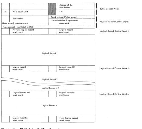
dures.-DATA BUFFER FORMAT
DCOS data buffers in the 7040 are 462
words in length. A buffer includes two
buffer control words and 460 words for
standard DCOS physical records. Each
phy-sical record contains two physical-record
control words, leaving 458 words for logi-cal records. Preceding the first word of
each logical record within a physical
record is a logical-record control word.
Figure 4 shows' the structure of the buffers and the format of the control words.
Buffer Control Words
The first two words of a data buffer are buffer control words. The address portion of word 1 contains a buffer chain address (i.e., the location of the next buffer). The first buffer control word of the last buffer in the chain contains the location of the buffer pool control word POOL. POOL contains the location of the first availa-ble buffer in the chain. If there· are no
buffers available, POOL contains its own
address.
When a buffer is being used for reading, the eecrement portion of the first buffer control word contains the location of a read posting routine. There is a posting routine for primary buffers (PPST) and a
posting routine for secondary buffers
(2PST) •
The second buffer control word is an
input/output command that is used to read data into and write data out of the buffer. The command is of the form:
lORD *+1,,460
Physical-Record Control Words
The first two words in standard DCOS physical tape and disk (drum) records are
control words. The contents of the two
words are different for tape records than
for disk (dr~ records except for the
decrement portion of the first word. The decrement portion of the first word always
contains an internally generated job
number.
For disk (drum) records, the address
portion of the first physical-record
con-trol word contains the record's t~ack
address. The decrement of the second con-trol word contains the track address of the previous physical record of the file, and its address contains the track address of the next physical record in the file.
For tape records, the address portion of the first physical-record control word con-tains the number of the record within the
current file. The second control word
contains the reel label in BCD form that was given/on a $SETUP card.
Logical-Record Control Words
preceding the first word of each logical record is the logical-record control word.
The decrement of this word contains the
word count of the previous logical record, and its address contains the word count of
the following logical record. The
remain-ing bits of the word, prefix and tag, are used to indicate the following.
S=o The previous logical record is
complete in this buffer.
S=1 The previous logical record is
incomplete in this buffer or ends in the last word of the previous buffer.
Form C28-6383-2 Page Revised 6/11/65
By TNL N28-0158-0
1=0
1=1
18=0
The previous logical record is a BCD record.
The previous logical record is a binary record.
The next logical record is complete in this buffer.
18=1 The next logical record is
incomplete in this buffer or starts in the first word of the next
buffer.
19=0
19=1
The next logical record is a BCD record.
The next logical record is a binary record.
INPUT SERVICE ROUTINE
The input service routine enters jobs
into the system, analyzes control cards,
initializes job description blocks, and
saves the jobs on the disk for later
processing. The jobs may be entered into the system through the 1402 card reader and/or as card images from a tape unit. Tape unit CO is used as an alternate input unit when the operator enters a code 35 in the 7040 console entry keys.
As the cards are entered into the sys-tem, they are moved from the input area
~DINA) to the input buffer (RDIN1). When the routine is ready to process another card, the next card in RDIN1 is moved to the work area (CRWKA). There i t is
com-pared to a table of control card types
(i.e., $JOB, $IOBASE, etc.). When a match
is found, control is transferred to the
routine that processes that card type.
Processing the cards consists of setting
switches to indicate the type of card, saving pertinent information for otherrou-tines, and building task descriptions for the job description block. If no match is found, the card is not a 7040 control card and is passed to the 7090 when the job goes on the 7090.
JOB SETUP
Jobs are set up by a group of routines that are entered through 7040 commutator
gate SETUP. At symbolic location SETUP,
there is a second commutator that controls setup routines that
1.
14
Analyze $ SETUP cards and code information for internal use.
the
2. Initialize 7040 unit control blocks,
7040 file control blocks, and 7040
background utilities.
3. Print tape mounting messages. 4. Execute 7040 background utilities. 5. Save information required for job
exe-cution (i.e., 7040 file control
blocks, IOBASE table, 7090 unit con-trol block information, etc.) on the disk (drum).
During the initialization phase of the
setup procedure, the job queue table is
searched for a job that requires setup. If there are no jobs that require setup, the 7040 setup commutator gate is closed and control is returned to the 7040 commutator at gate BRKDN. When a job requiring setup is found, its job description block is read from the disk (dru~ into 7040 core stor-age. The address portion of the first word of the setup task description contains the location of a file that, in turn, contains
the parameters of the $SETUP cards
asso-ciated with the job. Each $SETUP card has a six-word entry in the file. This file, known as the setup file, is then read into 7040 core storage.
$SETUP Card Analysis and Internal Coding
The six-word entries in the setup file contain the unit in the first word and the five parameters from the $SETUP card in the remaining words. This information is coded and condensed into a four-word setup file entry. The format of the four-word entry is shown in Figure 5 and is interpreted as follows:
WORD 1: Field 01 (bits S-2) is a
numeric code to represent option 1 and is interpreted as:
ident 1 0
DISK
=
1TAPE = 2
Field 02 (bits 3-5) is a numeric code to represent option
preted as:
ident 2 = 0
DISK 1
TAPE = 2
NORING 3
null (blank) = 4
PRINT = 5
PUNCH = 6
INPUT 7
Field 03 (bits 6-11) to represent option 3 preted as:
2 and is
inter-blank LABITS 720
= 0 1
=
2 (has no function as distributed)Unit is the unit specified, beginning in column 8 of the $SETUP card.
WORD 2: R (bits 18-20) will contain a 1 if REELS was specified in the
con-trol card. If REELS was not
speci-fied, R contains zero.
Form C28-6383-2 Page Revised 6/11/65
By TNL N28-0158-0
File count (bits 21-35) contains the file count parameter (FILECT) if i t was specified in the control card.
WORD 3: Ident 1 is a tape reel
identification if one was specified in
the option 1 field of the control
card.
WORD 4: Ident 2 is a tape reel
identification if one was specified in
the option 2 field of the control
card.
Address of the } next buffer
- - - 1 Buffer Control Words
* +1
3 Word count (460)
Previous logical record Logical record 1
word count word count Logical-Record Control Word 1
Logical record 1 word count
Logical record n-l word count
Logical record n word count
Logical Record 1
Logical Record 2 Logical Record n-l
Logical Record n
Logical record 2 word count
Logical record n word count
Next logical record word count
Figure 4. 7040 Data Buffer Format
Logical-Record Control Word 2
Logical-Record Control Word n
[image:15.613.48.520.242.669.2]Form C28-6383-2 Page Revised 6/11/65
By TNL N28-0158-0
Ident 1
Ident 2
Unit File count
.Figure 5. Four-Word Setup Entry
Initializing 7040 Background utilities
The setup routine determines whether any
pre-execution utility functions must be
performed on the input data. If the input file is not in the DCOS standard 460-word format, i t must be blocked into that format before i t is processed. If a $SETUP card
contains a reel identification in the
option 1 field and a reel identification or
the word TAPE or DISK in the option 2
field, pre-execution blocking must be per-formed.
If the routine execution blocking the 7040 units that utility routine and the utility.
determines that
pre-is required, i t assigns will be used by the initializes the call to
Initialize 7040 Unit Control Blocks and File Control Blocks
The unit analysis routine, UNANYL,
analyzes the unit specified on the $SETUP card. If the type of unit specified indi-cates that the job is to be run in the compatibility mode (i.e.,_ a true machine unit), the IOBASE specified in the $IOBASE card is used to determine which file con-trol block is to be used. If there was no
$IOBASE card with the job, the standard
DC-IBSYS IOBASE is used.
For all jobs that require setup, an
available file control block is selected for each unit specified on a $SETUP card.
For IOBASE 0, an available file control
block is one that is not reserved for a
specific library function, a peripheral
function, or a utility function. For
IOBASEl and IOBASE2, an available file
control block is one that is not reserved
for a library function or a peripheral
function. Any available file control block may be used for direct mode operation. The
specified IOBASE table defines the file
16
35
control blocks that are to be used for
compatibility mode.
A table is then generated for DC-IBSYS. This table, the UNISYM tab