Copyright to IJIRSET www.ijirset.com 2903
ANALYSIS AND MITIGATION OF STRESS CONCENTRATION
FACTOR OF A RECTANGULAR ISOTROPIC AND
ORTHOTROPIC PLATE WITH CENTRAL CIRCULAR HOLE
SUBJECTED TO IN-PLANE STATIC LOADING BY DESIGN
OPTIMIZATION
Shubhrata Nagpal
1, Dr. S. Sanyal
2, Dr. N.K.Jain
3Associate Professor,Department of Mechanical Engineering, Bhilai Institute of Technology, Durg (C.G.), India1
Professor and Head,Department of Mechanical Engineering, National Institute of Technology, Raipur (C.G.), India2
Assistant Professor, Department of Mechanical Engineering, National Institute of Technology, Raipur (C.G.), India3
Abstract: A number of analytical and numerical techniques are available for the two dimensional study of stress concentration around the hole(s) and notches in isotropic and orthotropic plates subjected to in-plane or transverse loading conditions. The influence of the structural dimension D/A (where D is hole diameter and A is plate width) ratio upon stress concentration factor for different cases is studied in the present work. Peculiarity in Stress concentration factor for different stresses like x, y, xy, von and deflection for different materials is observed. Stress concentration factor for all stresses shows marked mitigation upon introduction of auxiliary holes. Finite element method has been adopted for analysis and the results have been presented in graphical forms with discussion. The finite element formulation and its analysis are carried out using ANSYS package. This research work can provide structure engineers a simple and efficient way to estimate the effect of SCF and its mitigation in plate structures made of isotropic and orthotropic materials.
Key words
:
Finite Element Method, Stress Concentration Factor, Orthotropic Material, Mitigation of Stress Concentration Factor.NOMENCLATURE
A Width of plate (m)
D Diameter of hole (m)
Ex Modulus of elasticity for X direction Gxy Modulus of rigidity for XY plane σ Uniformly distributed load (N)
Kt SCF, Stress concentration factor = σmax / σnom L Length of rectangular plate, m
L1 Distance between centre of main hole and first set of auxiliary holes L2 Distance between centre of main hole and second set of auxiliary holes R1 Radius of first set of auxiliary holes, m
R2 Radius of second set of auxiliary holes, m t Thickness of plate (m)
defi Deflection in i direction in plate with hole defij Deflection in ij direction in plate with hole σX Normal stress in X direction
σY Normal stress in Y direction σVON Von - misses stress
τXY Shear stress in XY plane
Ҝ1 Percentage reduction in SCF for stress in X direction with one set of auxiliary hole Ҝ2 Percentage reduction in SCF for stress in X direction with two set of auxiliary hole
I.INTRODUCTION
Copyright to IJIRSET www.ijirset.com 2904
throughout the cross section. Failures such as fatigue cracking and plastic deformation frequently occur at the points of stress concentration.
Analytical solutions are available for stress concentration factor in the literature with different types of abrupt changes in shape for isotropic material and some specific orthotropic material.Jain and Mittal [1] have analyzed the stress concentration and deflection in isotropic, orthotropic and laminated composite plates with central circular hole subjected to transverse static loading by using two dimensional finite element method. Kotousov and Wang [2] have presented analytical solutions for the three dimensional stress distributions around typical stress concentrators in an isotropic plate of arbitrary thickness based on the assumption of a generalized plane strain theory. Troyani et al. [3] have determined the in-plane theoretical stress concentration factors for short rectangular plates with centered circular holes subjected to uniform tension using finite element method.
Ting et al. [4] and [5] presented the alternative method to study the stress distributions of the multiple circular or multiple elliptical holes with the rhombic pattern in the infinite domain. Ukadgaonker and Rao [6] proposed a general solution for stresses around hole in symmetric laminates under in-plane loading by introducing a general form of mapping function and an arbitrary biaxial loading condition to the boundary conditions, and the basic formulation is extended for multilayered plates.
Nagpal et al. [7] studied the stress distribution with central circular hole under in-plane static loading in rectangular isotropic plates and its mitigation . In the present work, an attempt has been made to identify the effect of angular distance on SCF around main circular hole. The interaction effect in stress concentration values in presence of auxiliary holes is also determined by determining the different stress concentration values in the Isotropic plate subjected to in-plane uni-axial loading.
Nagpal, Jain and Sanyal [8] presented the work of various researchers about stress concentration and its mitigation. They have discussed the various methods used by different researchers for stress analysis of plate with different singularities. Comparison of methods for determination of stress concentration and its mitigation has also been reported.
Rajaiah [9] worked on optimization of hole shapes in cylindrical shells under axial tension. A photo elastic and birefringent coating technique is useful. Optimal hole shape for minimum stress concentration in two dimensional finite plates using parameterized geometry models are given by Zhixue Wu [10].
Sanyal [11] proposed multiple relief holes around the main hole in infinite thin plates for reduction of stress concentration using Finite element method for analysis.
Meguid [12] presented a technique for reduction of SCF in a uniaxially loaded plate with two coaxial holes by introducing defense hole system. Finite element method was used for analysis. Three systems for defence holes were described for FEM analysis.
Toubal et al. [13] studied experimentally for stress concentration in a circular hole in composite plate.
Upon review of the literatures available, Analysis of more cases of stress concentration in composite plates with hole subjected to transverse loadings needs to be further investigated in detail.
In this paper a study of isotropic and orthotropic plate with central circular hole for the effect of D/A ratio on SCF under in plane static loading condition is made by using two dimensional finite element analyses. The purpose of this research work is to investigate the effect of D/A ratio on SCF for normal stress in X, Y directions (σx, σy), shear stress in XY plane, von mises stress and deflection in XY plane. Further the mitigation of SCF has been done by providing auxiliary holes around main circular hole. The size of auxiliary hole and its position has been optimized. The significant mitigation in SCF for all the cases has been reported.
The analytical treatment for such type of problem is very difficult and hence the finite element method has been adopted for complete analysis. Isotropic material and four types of orthotropic materials are used for analysis to find out the sensitivity of SCF with respect to D/A ratio. The work also illustrates, the mitigation of SCF versus hole diameter to plate width ratio in plate of different materials.
II. DESCRIPTION OF PROBLEM
The objective of this paper is to provide structural engineers a simple and reliable estimation method for SCFs and its mitigation in common structures. For this purpose, a systematic study of SCFs and its mitigation for isotropic/orthotropic plates containing a circular hole was carried out.
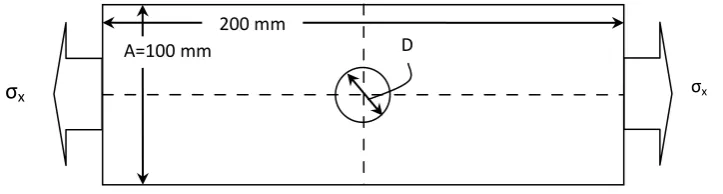
Based on the SCFs of an isotropic plate and superposition principle, a simple computational method is proposed to estimate SCFs of an isotropic plate under one way loading and then this method has been extended to orthotropic structures. The proposed method is to study a plate of dimension 200mm X 100mm X 1mm with a circular hole at centre under uniform distributed
Copyright to IJIRSET www.ijirset.com 2905 200 mm
A=100 mm D
σ
x σxFig1. Model of plate with central circular hole under in plane static loading
Plate has been modified for mitigation of SCF around circular hole. A material is isotropic if its mechanical and thermal properties are same in all directions. Isotropic materials can have homogeneous or non-homogeneous microscopic structures. An orthotropic material has at least two orthogonal planes of symmetry, where material properties are independent of direction within each plane. Such materials require nine independent variables (i.e. elastic constants) in their constitutive matrices.
TABLE 1
MATERIAL PROPERTIES Materials
Properties Isotropic E-glass/
Epoxy Boron/ epoxy Boron/ aluminum Woven Glass/Epoxy
Ex Ey Ez Gxy Gyz Gzx νxy νyz νzx 39GPa - - - - - 0.3 - - 39 GPa 8.6GPa 8.6GPa 3.8GPa 3.8GPa 3.8GPa 0.28 0.28 0.28 201 GPa 21.7GPa 21.7GPa 5.4 GPa 5.4 GPa 5.4 GPa 0.17 0.17 0.17 235 GPa 137 GPa 137 GPa 47 GPa 47 GPa 47 GPa 0.3 0.3 0.3 29.7GPa 29.7GPa 29.7GPa 5.3GPa 3.3GPa 3.3GPa 0.17 0.17 0.17
III.FINITE ELEMENT ANALYSIS
Finite element method was chosen for analysis of the model. The model was generated using a 3-D solid element, Solid 186, in ANSY software. The element Solid 186 with three degrees of freedom per node and 20 nodes per element shows high stress stiffening capabilities. Typical mesh of the plate using the above element has been shown in Fig.2. Mapped meshing is used for all models with more elements employed near the hole boundary. Element length is decided as 2mm after checking the convergence. Results were then displayed by using post processor of ANSYS Software.
The isotropic/orthotropic plate with central circular hole subjected to in plane loading has been analysed. One set of auxiliary hole is introduced around the main hole. The optimum size and the optimum position of the auxiliary holes have been proposed after analysing the plate with different size of holes at different positions.
Copyright to IJIRSET www.ijirset.com 2906
Fig.2 Rectangular Plate with Central Circular hole and one Auxiliary hole
For further mitigation in SCF two sets of auxiliary holes has been introduced at optimum position and of optimum size.
Fig.3. Element Structural Solid Geometry and generated mesh of the plate
IV.RESULT AND DISCUSSION
Numerical results obtained from 2D finite element analysis for three different case studies of uni-axial loaded rectangular isotropic and orthotropic plate are given.
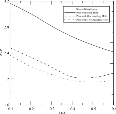
Maximum reduction in SCF has been reported by providing two sets of auxiliary holes around the main hole at optimum position, L1=1.25R+R1 and L2=1.25R+2.25R1+R2. The optimum size of auxiliary hole has been reported as R1=0.9R and R2=0.9R1.By increasing the number of auxiliary hole sets from two to three very small increase in SCF has been reported.
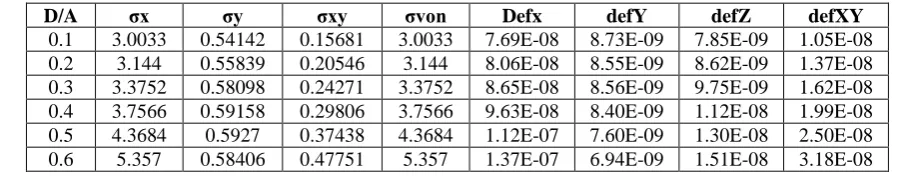
Variation in stresses and deflection for D/A ratio from 0.1 to 0.6 has been presented in Table 2 to Table 6, for all the materials considered. The magnitude of stresses in X direction is maximum for all D/A ratio and for all materials as compared to other stresses. The magnitude of all the stresses increases as D/A ratio increases. For studying the effect of area reduction method for mitigation of SCF, stresses in X direction is most significance.
TABLE 2.VARIATION IN DIFFERENT STRESSES AND DEFLECTION IN PLATE WITH CENTRAL CIRCULAR HOLE OF ISOTROPIC MATERIALS FOR DIFFERENT D/A RATIO
D/A σx σy σxy σvon Defx defY defZ defXY
0.1 3.0033 0.54142 0.15681 3.0033 7.69E-08 8.73E-09 7.85E-09 1.05E-08
0.2 3.144 0.55839 0.20546 3.144 8.06E-08 8.55E-09 8.62E-09 1.37E-08
0.3 3.3752 0.58098 0.24271 3.3752 8.65E-08 8.56E-09 9.75E-09 1.62E-08
0.4 3.7566 0.59158 0.29806 3.7566 9.63E-08 8.40E-09 1.12E-08 1.99E-08
0.5 4.3684 0.5927 0.37438 4.3684 1.12E-07 7.60E-09 1.30E-08 2.50E-08
0.6 5.357 0.58406 0.47751 5.357 1.37E-07 6.94E-09 1.51E-08 3.18E-08
Copyright to IJIRSET www.ijirset.com 2907 TABLE 3. VARIATION IN DIFFERENT STRESSES AND DEFLECTION IN PLATE WITH CENTRAL CIRCULAR HOLE OF E-
GLASS/EPOXY FOR DIFFERENT D/A RATIO
Considering E glass /epoxy Table3 the stress in X direction shows increase with D/A ratio showing magnitude of stress more than that for Isotropic material. Also, stress in Y direction increases. Shear stress increases with D/A ratio. Von-mises increases with D/A and almost equal to stress in X direction. Deflection in X direction, Y direction, Z direction & in XY plane does not show any trend.
TABLE 4. VARIATION IN DIFFERENT STRESSES AND DEFLECTION IN PLATE WITH CENTRAL CIRCULAR HOLE OF BORON/EPOXY FOR DIFFERENT D/A RATIO
D/A σx σy σxy σvon defx defY defZ defXY
0.1 5.3482 0.1717 0.0645 5.3482 2.66E-11 6.77E-12 2.50E-12 1.19E-11
0.2 6.2654 0.16731 0.0624 6.2654 3.11E-11 7.10E-12 2.82E-12 1.16E-11
0.3 6.9726 0.17002 0.0726 6.9726 3.47E-11 7.15E-12 3.22E-12 1.35E-11
0.4 7.7172 0.17582 0.0881 7.7172 3.84E-11 7.34E-12 3.73E-12 1.63E-11
0.5 8.6332 0.18401 0.10723 8.6332 4.29E-11 7.56E-12 4.36E-12 1.99E-11
0.6 9.9188 0.23938 0.13254 9.9188 4.93E-11 1.02E-11 5.13E-12 2.45E-11
Boron Epoxy shows Table4, stress in X direction increases with D/A ratio with magnitude of stress more than that for E glass /epoxy. Stress in Y direction increases but magnitude is less than other materials. Shear Stress increases with D/A ratio. Von-mises increases with D/A and almost equal to stress in X direction. Deflection in X direction increases with D/A ratio with Y direction not showing any movement. Deflection in Z & XY plane show upward movement with D/A ratio.
TABLE 5 VARIATION IN DIFFERENT STRESSES AND DEFLECTION IN PLATE WITH CENTRAL CIRCULAR HOLE OF BORON/ALUMINUM FOR DIFFERENT D/A RATIO
D/A σx σy σxy σvon defx defY defZ defXY
0.1 3.5156 0.41555 0.11665 3.5156 1.49E-11 2.00E-12 1.67E-12 2.48E-12
0.2 3.7332 0.41812 0.15306 3.7332 1.59E-11 2.11E-12 1.84E-12 3.26E-12
0.3 3.9864 0.42898 0.17794 3.9864 1.70E-11 2.11E-12 2.07E-12 3.79E-12
0.4 4.3751 0.43895 0.21399 4.3751 1.86E-11 2.08E-12 2.35E-12 4.55E-02
0.5 4.9887 0.44578 0.26239 4.9887 2.12E-11 1.98E-12 2.67E-12 5.58E-12
0.6 5.9814 0.44988 0.3268 5.9814 2.54E-11 1.76E-12 3.04E-12 6.95E-12
Analyzing the material Boron / Aluminum Table 5, Stress in X direction shows increase with D/A ratio magnitude of stress is less as compared to Boron Epoxy & E glass. Stress in Y direction increases with D/A ratio. Shear Stress increases with D/A ratio. Von-mises increases with D/A and is almost equal to stress in X direction. Deflection in X direction increases with D/A ratio with Y direction not showing any movement. Deflection in Z & XY plane show
upward movement with D/A ratio
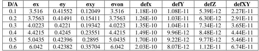
TABLE 6.VARIATION IN DIFFERENT STRESSES AND DEFLECTION IN PLATE WITH CENTRAL CIRCULAR HOLE OF WOVEN-GLASS/EPOXY FOR DIFFERENT D/A RATIO
D/A σx σy σxy σvon defx defY defZ defXY
0.1 3.516 0.41552 0.12049 3.516 1.18E-10 1.08E-11 5.39E-12 2.27E-11
0.2 3.7563 0.41491 0.15411 3.7563 1.26E-10 1.03E-11 6.30E-12 2.91E-11
0.3 4.0223 0.4221 0.19342 4.0223 1.35E-10 1.04E-11 7.34E-12 3.65E-11
0.4 4.4215 0.4245 0.23551 4.4215 1.49E-10 9.96E-12 8.48E-12 4.44E-11
0.5 5.0435 0.42396 0.2895 5.0435 1.70E-10 9.22E-12 9.77E-12 5.46E-11
0.6 6.042 0.42382 0.35704 6.042 2.03E-10 8.07E-12 1.12E-11 6.74E-11
D/A σx σy σxy σvon defx defY defZ defXY
0.1 4.217 0.2771 0.0901 4.2169 1.08E-10 2.79E-11 1.53E-11 2.37E-11
0.2 4.6214 0.28874 0.10286 4.6214 1.18E-10 2.75E-11 1.66E-11 2.71E-11
0.3 4.961 0.2957 0.11884 4.961 1.27E-10 2.79E-11 1.84E-11 3.13E-11
0.4 5.4041 0.30676 0.14033 5.4041 1.38E-10 2.86E-11 2.07E-11 3.69E-11
0.5 6.063 0.31926 0.57123 3.7213 9.54E-07 3.13E-08 7.92E-08 1.50E-07
Copyright to IJIRSET www.ijirset.com 2908
Considering Woven-Glass Epoxy Table 6, stress in X direction shows upward movement with D/A ratio.
Magnitude of stress is nearly equal to that of Boron Aluminum. Stress in Y direction increases with D/A ratio. Shear Stress goes upward with D/A ratio. Von-mises increases with D/A and almost equaling that of X direction. Deflection in X direction increases with D/A ratio. Deflection in Y & Z direction does not show any trend whereas deflection in XY plane increases with D/A ratio.
Copyright to IJIRSET www.ijirset.com 2909
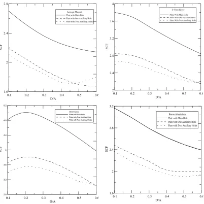
Fig.4. Variation of SCF vs D/A (1)isotropic (2) eglass/epoxy (3) boron/epoxy (4) woven-glass/epoxy (5) boron/ aluminium.
Table 7 below represents the percentage of reduction in SCF for stress in X direction for all D/A ratio by introducing first one set & then two sets of auxiliary holes. The percentage reduction for various D/A ratio does not follow any trend. For Isotropic material percentage reduction reported is 18.6% to 22.2% with one set of auxiliary hole & 15.9% to 23.27% for two sets of auxiliary holes. Maximum reduction is found to be 23.27% for D/A =0.4 with two sets of auxiliary holes.
Whereas for E glass / Epoxy the percentage reduction range from 23% to 25 % for one set and 23.5% to 29.5% for two sets and maximum reduction for D/A ratio=0.1 with two sets of auxiliary holes is observed as 29.5%.
In the material Boron Epoxy the percentage reduction range from 23% to 24 % for one set and 22.3% to 29.2% for two sets and maximum reduction for D/A ratio=0.1 with two sets of auxiliary holes is found to be 29.25% .
Considering Boron Aluminum the percentage reduction range from 20% to 29.7 % for one set and 18.9% to 26.6% for two sets. Maximum reduction for D/A ratio=0.4 with one set of auxiliary holes is found to be 29.74%.
And lastly for Woven Epoxy the percentage reduction range from 15% to 23.3 % for one set and 17.9% to 27% for two sets. Maximum reduction for D/A ratio=0.2 with two sets of auxiliary holes is found to be 27%.
TABLE7. PERCENTAGE REDUCTION IN SCF(STRESS IN X-DIRECTION) FOR ALL D/A
D/A
Isotropic E-glass/epoxy Boron/epoxy Boron/aluminum
Woven-Glass/Epoxy
Ҝ1 Ҝ2 Ҝ1 Ҝ2 Ҝ1 Ҝ2 Ҝ1 Ҝ2 Ҝ1 Ҝ2
0.1 18.95 21.77 25.02 29.54 24.03 29.25 27.58 25.11 21.60 25.27
0.2 18.68 22.00 24.14 29.01 23.97 29.15 28.41 26.67 22.37 27.01
0.3 19.64 21.90 23.15 28.23 23.22 28.31 27.77 26.16 22.48 26.55
0.4 20.93 23.27 23.30 27.78 23.04 27.59 29.74 25.75 23.39 25.36
0.5 22.20 21.11 24.15 26.66 23.22 26.77 24.59 23.50 19.86 22.59
Copyright to IJIRSET www.ijirset.com 2910
Copyright to IJIRSET www.ijirset.com 2911
Copyright to IJIRSET www.ijirset.com 2912
Fig.7. Variation of deflection) x vs D/A (1)isotropic (2) eglass/epoxy (3) boron/epoxy (4) woven-glass/epoxy (5) boron/ aluminium.
V. CONCLUSION
Copyright to IJIRSET www.ijirset.com 2913
The SCF follows a symmetric trend with respect to D/A ratio in all cases. On the basis of results obtained, it has been seen that the SCF is sensitive to D/A and material properties. The results obtained show that for higher values of D/A, SCF is also higher.
SCF reducing as D/A increases. Shear stress increases with introduction of auxiliary holes. Shear stress is maximum with set of auxiliary hole then reduces with two set of auxiliary hole. Deflection in X direction increases with D/A ratio for all the materials.
Deflection in X direction increases in isotropic material by introducing auxiliary holes. Deflection in X direction decreases in E glass epoxy and Boron Epoxy material by introducing one and then two sets of auxiliary holes. In Boron aluminium, by introducing one set of auxiliary hole the deflection reduces. With two set of auxiliary holes deflection increases for D/A=0.3, than shows downwards trend. In Woven glass epoxy with one set of auxiliary hole deflection increases for D/A=0.1, then showing downward trend. With two set of auxiliary hole deflection reported is less then that with main hole only.
Maximum mitigation in SCF reported is 29% in SCF)X .
ACKNOWLEDGMENT
The authors acknowledge the institute authorities for supporting the present work to be carried out in the institute.
REFERENCES
[1] Jain N K, Mittal N D, ―Finite element analysis for stress concentration and deflection in isotropic, orthotropic and laminated composite plates with central circular hole under transverse static loading‖, Materials Science and Engineering A 498 2008: 115-124.
[2] Kotousov A, Wang CH., ―Three-dimensional stress constraint in an elastic plate with a notch‖, International Journal of Solids and Structures 2002; 39: 4311-4326.\
[3] Troyani N, Gomes C, Sterlacci G. ,―Theoretical stress concentration factors for short rectangular plates with centered circular holes‖,Journal of Mechanical Design 2002; 124: 126-128. [4] K. Ting, K.T. Chen, W.S. Yang, Nuclear Engineering and Design 187 (1999) 303-313.
[5] K. Ting, K.T. Chen, W.S. Yang, International Journal of Pressure Vessels and piping 76 (1999) 503-514. [6] V.G. Ukadgaonker, D.K.N. Rao, Composite Structure 49 (2000) 339-354.
[7]Shubhrata Nagpal, Dr. Nitin Jain, and Dr. S. Sanyal ,―Interaction Effect of Auxiliary holes for Mitigation of Stress Concentration in Isotropic Plate with Central Circular Hole Subjected to in Plane Loading‖ , International Journal of Mechanics & Solid, ISDN 0973-1881 Volume- 6 Number-2 (2011), PP 149-156
[8]Shubhrata Nagpal, Nitin Jain, and Shubhashish Sanyal, ―Stress Concentration and its Mitigation Techniques in Flat Plate with Singularities—A Critical Review‖, Engineering Journal Volume 16 Issue 1, pg1-16,January 2012.
[9] Durell .A.J and Rajaiah.K , ―Optimum hole shapes in finite plates under uni- axial load ‖, Applied Mechanics 46(3) , 691-695(1979). [10]Zhixue Wu, ―Optimal hole shape for minimum stress concentration using parameterized geometry models‖, Springer, 2008.