Coherence Function Method for Detecting
Inter-Turn Fault in HVDC Converter
Transformer
Koganti Sri lakshmi, G. Sravanthi
2,L. Ramadevi
3,
Koganti Harish Chowdary
4Assistant Professor, Dept. of EEE, SNIST, Hyderabad, Telangana, India 1 Assistant Professor, Dept. of EEE, SNIST, Hyderabad, Telangana, India 2 Assistant Professor, Dept. of EEE, SNIST, Hyderabad, Telangana, India 3
PG Student [EEE], Dept. of EEE, Hyderabad, Telangana, India 4
ABSTRACT: This paper intends to detect the inter-turn fault by performing impulse test on HVDC Converter transformer by Coherence Function method. The inter-turn in a transformer (due to insulation failure) is located in impulse test by neutral current method. In the neutral current method, a record of the impulse current flowing through a resistive shunt between the neutral and ground point is used for detecting the fault. Neutral current so measured or calculated is in time domain. Theoretically the calculated neutral current, both for healthy winding and turn-fault winding is subjected to FFT to convert time domain into frequency domain of real and imaginary values. The real and imaginary values are used to calculate the coherence function. Coherence function compares both with and without fault neutral current in frequency domain, so that fault can be identified. Coherence function compares input and output at each frequency.It displays output i.e coherence value as 1 if input and output at that frequency is same other wise less than 1. 1 indicates that there is no fault at that frequency and decreasing coherence value (<1) indicates fault at that frequency.
KEYWORDS: HVDC converter transformer, Coherence function, FFT.
I.INTRODUCTION
HVDC transmission has been gaining popularity ever since its first commercial operation in 1954. The advent of HVDC technology [1] has been so rapid that it is widely applied all over the world for bulk power transmission over long distances. It is popularly employed for interconnecting two asynchronous systems not only through overhead lines but also through submarine cables. The power supply is made available to islands and remote places by means of HVDC Transmission.
HVDC systems are also gaining importance because of the increased use of renewable energy resources for power generation. HVDC systems are used to transmit electricity from remotely located non conventional energy sources to thickly populated cities. Even in conventional power stations, it is easier to transmit electricity by HVDC from a remotely located power station closer to the location of the coal or natural gas, rather than to set up a power station closer to the thickly populated city and to transport coal from remotely located coal mines.
The failure analysis of HVDC systems reported by CIGRE [4] states that out of 22 failures in the last few years, 14 failures were secondary winding failures. In India, almost all failures have taken place on the secondary windings of the converter transformers. Such failures have been attributed to corrosive oil-forming copper sulphide sediments, voltage transients arising during the commutation process, and temperature rise.
It has also been recommended that repetitive voltage transients initiate partial discharge and eventually result in the failure of the converter transformer [5], [6]. The harmonic leakage fluxes because thermal problems in the converter transformer which may lead to its failure as discussed in [7]. Grant and Mc Dermid in [8] confirmed that a converter transformer shows signs of insulation degradation due to thermal aging after a few decades of normal operation. In this paper, an attempt has been made to analyse the HVDC system from an electrical power engineer’s point of view to realize the origin reason for the failure of the converter transformer secondary. Some solutions have also been suggested to eliminate these problems.
II. HVDC CONVERTER TRANSFORMER AND IMPULSE TESTING
The function of the impulse test is to find out the capability of insulation of the transformers to bare the transient voltages due to lightning, As transients are impulses of short rise time, the voltage distribution along the transformer winding does not stay uniform for quick rising voltages. Fault investigation and diagnostics of HVDC converter transformers are essential, as power quality and reliability is one of the important factors for the electric power system. Insulation failure within transformer is treated to be one of the most important causes of complete failure of HVDC transformers. In order to evaluate the reliability of the winding, specific high voltage test is conducted on the transformer. To avoid large over-voltages being induced in the winding, components which are not under test short circuit and connected to ground.
Fig.2.1.Scematic diagram of transformer under test
The schematic diagram of the transformer connection for high voltage impulse testing is shown in figure 2.1. In transformer testing, it is necessary to record the wave forms of the applied voltages and currents from the winding which is under test. It is also important that the grounding must be proper and the windings which are not under test are correspondingly terminated.
III. TECHNICAL DATA AND RATINGS OF ALL EQUIPMENTS USED IN HIGH VOLTAGE TESTIMPULSE GENERATOR
Impulse generators used for testing must have adequate capacitance per stage so that it does not cause loading of impulse generator during test. Typically for a 400kV transformer where lighting impulse test voltage 1425kV, the impulse generator rating could be of the order of 2MV, stage capacitance 0.5uF, charging voltage 200kV/stage, having 10 stages a total energy of 100kJ. The present study is on the basis of theoretical calculation and voltage applied for study is unity. The data can be extrapolated for the star winding impulse test voltage of 1550kV.
B. TEST TRANSFORMER: Single phase of the HVDC converter transformer of power ratings 315MVA, 400/√3 /206/√3 kV is shown in the Fig.3.1. Figure shows the constructional geometry of one limb, comprising Tapping, HVAC and HVDC winding. For the purpose of neutral current calculations, the tapping winding has been fully earthed as is done in impulse test.
Fig.3.1.HVDC converter transformer under test
C. FORMULATION OF EQUIVALENT ELECTRICAL NETWORK: HVDC winding has been considered for analysis which has 246 discs. The HVAC windings are divided into 8 sections and HVDC windings are divided into 16 sections. Number of turns in each section is given by 246/16=15.4. Based on the no of turns in the section, paper insulation thickness, physical clearance between the windings and ducts, the calculations of self and mutual inductances, series and ground capacitance have been carried out. The network is suitably formed. The network is solved for Eigen Voltages values and frequency and finally the neutral currents are calculated. (The above data is obtained from BHEL R&D). Fig 3.2. Shows the schematic diagram of the three windings of one limb of HVDC transformer.
Fig.3.2.Sectional distribution of HVDC converter transformer
IV. DETECTION OF FAULT DURING IMPULSE TESTING
The inter-turn in a transformer (due to insulation failure) is located in impulse test by neutral current method. In the neutral current method, a record of the impulse current flowing through a resistive shunt between the neutral and ground point is used for detecting the fault. Neutral current so measured or calculated is in time domain.
to FFT [Fast Fourier Transformation] for determination of dominant frequencies. FFT is used to convert time domain into frequency domain of real and imaginary values. The real and imaginary values are used to calculate the coherence function. Coherence function compares both with and without fault neutral current in frequency domain, so that fault can be identified.
Let’s assume that f(t) and g(t) are the input and output signals of the system and, F(f) and G(f) the related complex Fourier Transforms. The coherence function is mathematically defined as:
The Fast Fourier transform (FFT) spectrum analyser gives the computation and display of the coherence function conjunction with the output spectrum to allow an efficient comparison between the coherence function variants and the related output spectra components.
V. IMPLEMENTATION OF COHERENCE FUNCTION IN INTER-TURN FAULT DETECTION
A suitable computer programme has been developed to coherence function for fault determinations. To identify fault calculations we substitute the real i.e. Re(F(f)) and imaginary i.e. Im(F(f)) values of neutral current through a healthy winding at a particular frequency (f) after determining FFT as input to the coherence function equation i.e. Re(γ2) and real i.e. Re(G(f)) and imaginary i.e. Im(G(f)) values of neutral current through a faulty winding at a particular frequency(f) after determining FFT as output to coherence equation.
Coherence function as a tool compares input and output at each frequency. It displays output i.e coherence value as 1 if input and output at that frequency is same. Otherwise less than 1. 1 indicates that there is no fault at that frequency and decreasing coherence value (<1) indicates fault at that frequency.
VI. RESULTS
A typical neutral current signal from a healthy winding and its corresponding Fourier Transform is shown in Fig.7.1.
Fig 7.1: Neutral current in Time and frequency domains without fault
Neutral current with single turn fault and it Fourier transform is shown in Fig.7.2.
Fig 7.2: Neutral current in Time and frequency domains with single-Turn fault
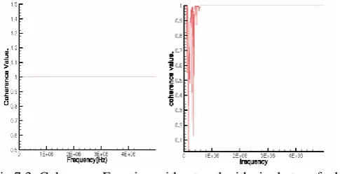
Fig.7.3. shows the Coherence Function output signal when both given input and output functions are same signal. Since the signal is same, the imaginary value of the Coherence Function is zero and all real values are unity. The Coherence Function with single turn fault is shown in Fig.7.3.
Fig 7.3: Coherence Function without and with single turn fault
Fig 7.4: Neutral current in Time and frequency domains with Two-Turn fault
A neutral current with two turn fault and middle turn fault and its corresponding Fourier transforms is shown in Fig.7.5
Fig 7.5: Neutral current in Time and frequency domain signals when fault is at middle of the winding
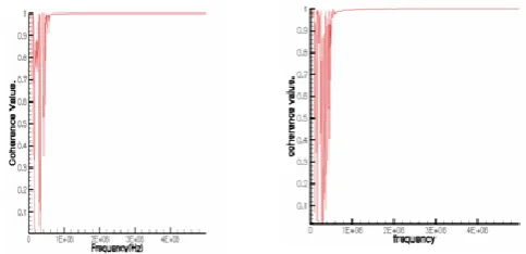
Whereas Fig.7.6. Shows the coherence functions of the two turn and middle turn faults respectively.
Fig 7.6: Coherence Function for two-turns & fault at the middle of winding
VII.CONCLUSION
severity of fault. More computation needs to be carried out by simulating fault along coil depth (CD) of the HVDC winding. In order to reduce the error in computation it is desirable to calculate current for longer duration. However, the Coherence check can prove to be a good tool for determining fault in the winding.
REFERENCES
1. Albert Claudi, Matthias Loppacher, “New methods for improving the reliability of Non-Destructive high voltage testing” Haefely publication, 1998.
2. P.Krishna Murthy, Dr.J.Amarnath, Dr. B.P.Singh, “Reconstruction of HVDC Converter Transformer Neutral Current using Gabor Wavelet”, IEEMA Journal 2009.
3. L. Satish, “Short time Fourier and wavelet transform for fault detection in power transformer during impulse tests”,IEEE Proc Vol.145, March 1998.
4. B.P.Singh, K.K.Kishore, KSR Sheriff and A Bhoomaiah, “Adoption of Transfer Function Technique for failure analysis of transformer winding Conference on Electrical Insulation and Dielectrical phenomena”, Ausitn, Texas, USA oct17-21, 1999.
5. S.C .Guptha and B.P.Singh, “Determination of Impulse Voltage distribution in winding and large power transformers”, Electric power system Research, 25(1992), pp 183-189.
6. Roberto rudervall, J.P.Charpentier, Raghuveer Sharma, “High voltage direcrt current transmission systems technology review paper”. 7. R.Suri, R.S.Moni, “The second 1×500MW HVDC back-to-back inter connection at vizag”, ABB publications.
8. Ake Carlson, “Specific requirements on HVDC converter transformers”, ABB publications.
BIOGRAPHIES
Koganti sri lakshmi was born in India in 1983. She received the B.Tech. and M.Tech. Degrees in electrical engineering from the JNTU University, Hyderabad, A.P., India, in 2006 and 2009, respectively, currently, she is working as Assistant Professor in Electrical Engineering department of SNIST. Her current research interests include Renewable energy, HVDC, Smart Grid, power quality, FACTS, and HVAC.
G. Sravanthi was born in India in 1987. She received the B.Tech. and M.Tech. Degrees in electrical engineering from the JNTU University, Hyderabad, A.P., India, in 2008 and 2010, respectively, currently, she is working as Assistant Professor in Electrical Engineering department of SNIST. Her current research interests include Renewable energy, power quality, FACTS, Power electronics, Smart Grid.
L.Ramadevi was born in India in 1985. She received the B.Tech. Degree in electrical engineering from JNTU University, Hyderabad, A.P., India, in 2006 and M.Tech from Acharya Nagarjuna University, A.P in 2010.Presently she is Persuing Ph.D in Acharya Nagarjuna University, A.P. Currently, she is working as Assistant Professor in Electrical Engineering department of SNIST. Her current research interests include Renewable energy, Optimization techniques, Realiability, Distribution Generation, Smart Grid.