CSEIT172610 | Received : 01 Nov 2017 | Accepted : 08 Nov 2017 | November-December-2017 [(2) 6: 27-31]
International Journal of Scientific Research in Computer Science, Engineering and Information Technology © 2017 IJSRCSEIT | Volume 2 | Issue 6 | ISSN : 2456-3307
27
Design and Fabrication of Rheocasting Mould System
Dr. Nirmal Kumar Kund
Associate Professor, Department of Production Engineering, Veer Surendra Sai University of Technology, Burla, Odisha, India
ABSTRACT
The vital component of the present design and development related research work is the demonstration of the experimental setup and practice for rheocasting experiments using stirrer for molten Al alloy and appropriate instrumentation to realise the same. The design of experiments includes selecting a suitable Al alloy for SSF, designing and developing an experimental technique for conducting rheocasting experiments. In this work, a physical process is considered which represents a rheocasting process in presence of electromagnetic stirring. This includes a comprehensive description of the CAD model showing details design of the various rheocasting mould components, snapshot of physically developed rheocasting mould used for experiments, snapshot of disassembled rheocasting mould together with both CAD model and snapshot of mould cooling with water jet impingement. It also describes the process variables which affect the transport phenomena during processing. In addition, a variable viscosity model is used to represent the fluid as semisolid slurry. The usual safety measures are also followed in the present experimental designs and fabrication procedures by keeping in view all the pertinent design/development aspects.
Keywords: Design, Development, Rheocasting, Mould.
I.
INTRODUCTION
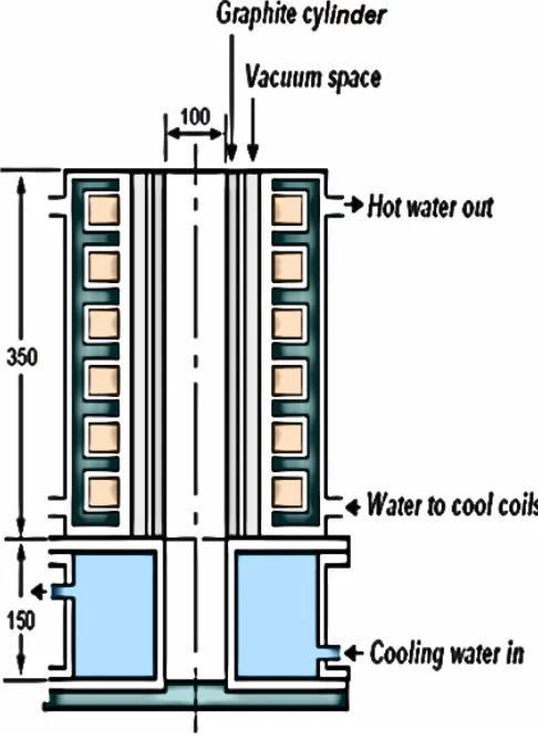
Among all the solidification modelling techniques, the rheocasting practice in presence of electromagnetic stirring is unique one because of the near net shape along with the productivity. It uses a variable viscosity model of slurry in the transport process to represent the fluid as semisolid slurry. In the solidification modelling process used in the present research, a cylindrical mould is considered for production of a rheocast billet of 100 mm diameter and 500 mm length. Figure 1 shows a schematic diagram of the mould. The mould consists of two parts. The upper part of the mould is surrounded by a linear electromagnetic stirrer of 350 mm length, which is the zone of active stirring. The lower part of the mould (150 mm length) is used to cool the liquid metal. In the upper portion of the mould, an electrically non-conducting clay graphite crucible and vacuum chamber surrounding the mould are constructed, as shown in figure 1, with the aim of minimizing the radial heat transfer. The top surface of the mould is open to atmosphere whereas the bottom surface is closed by an adiabatic ceramic plate. Based on the physical problem described above, a 2D
axisymmetric geometry is considered for numerical simulation. In the present research, molten A356 Al alloy having 7.32 % Si is chosen for solidification processing in presence of electromagnetic stirring, which is commonly used for casting applications. The initial temperature of the alloy is 623°C. A water (or air) cooled stainless steel mould is introduced at the bottom of the refractory tube for removing heat (q) from the molten Al alloy.
II.
KEY DESIGN PROCESS PARAMETERS
Figure 1. Schematic of rheocasting arrangement.
A. Viscosity of Semisolid Slurry
The semisolid slurry viscosity exhibits a unique behaviour compared to that of s pure liquid, which increases the flow complication during processing. The effective viscosity of the slurry depends on several process parameters. In the present research work, the slurry viscosity is represented as a variable viscosity function which considers the process parameters for better understanding of the semisolid processes. Congruently, a constitutive relation is developed for the variable viscosity using a concentric cylinder viscometer.
B. Stirring Intensity
The stirring intensity is a vital parameter influencing the final properties of the rheocast billets. The microstructures obtained in the billets may be rosetted or globular, depending on the stirring intensity. In electromagnetic stirring, a minimum stirring intensity is required to activate the shearing of dendrites at the solid/liquid interface which depends on the magnitude of the Lorentz force. The Lorentz force depends mainly
on the current input to the coils. Accordingly, the selection of current can be made, which produces sufficient Lorentz force to shear the dendrites. In addition, the distributions of solid fraction and species also depend on stirring intensity. Therefore, in the present work, the effect of stirring intensity on transport phenomena is taken into account.
C. Cooling Rate
It is observed that cooling rate during semisolid processing is also an essential parameter affecting the final product. In the present work, the bottom mould is cooled with different cooling heat fluxes (q/3.5, q and 2.5q) in order to explore the effect of cooling rate on transport phenomena for the present solidification process. The cooling heat flux ‘q’ corresponds to the extraction of heat from the molten liquid using water which passes through the cooling jacket (cooling rate ∼
6 °C/min). The cooling heat flux ‘q/3.5’ corresponds to the removal of heat from the molten liquid using air which passes through the cooling jacket (cooling rate ∼
1 °C/min).. The cooling heat flux ‘2.5q’ symbolises the removal of heat at higher rate from the liquid metal (cooling rate ∼ 15°C/min).
III. DESIGN OF RHEOCAST MOULD
the linear EMS. This arrangement will allow active control of cooling of the metal from the bottom of the mould. Since the high temperature molten aluminium at comes in contact with the cold mould surface, the mould material should have high thermal shock resistance. In addition, the material should be non-wetting to liquid aluminium. Among the engineering refractory materials available, graphite is the most suitable option for such an application. A certain proportion of clay is mixed to improve mechanical properties and to reduce electrical conductivity. In order to prevent oxidation, the graphite mould is pre-coated with anti-oxidation coating on the outside and boron nitride on the inside. A standard practice is to provide a taper in the mould to aid easy extraction of the casting at the end of the experiment (refer to CAD model of figure 2). Accordingly, the mould is tapered at ∼ 8° towards the top. Hence, in the present case, the diameter at the mouth of the crucible is set to 95 mm. The graphite mould is kept in an SS 304 (non-magnetic) seamless tube of 125 mm inner diameter and 5 mm wall thickness to retain structural integrity. Additionally, any inadvertent crack of the mould will give rise to internal breakdown into the liquid metal chamber.
Figure 2. CAD model showing details of rheocasting mould.
The bottom part of the mould is a region of active cooling. This portion is principally made of metal to attain high cooling rates. In this zone, the metal cools down rapidly to form a solid mass which, in turn, will extract heat from the molten column of liquid metal above it. It is also outside the zone of the electromagnetic field. Fluid motion in this zone may take place owing to the inertia of the molten metal
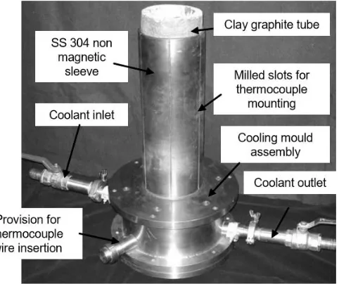
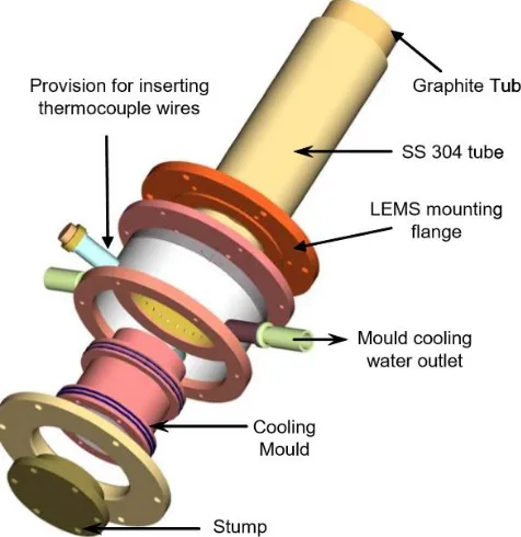
column on top of it. Ideally, mould design should be such that a stable solid-liquid interface advances from the bottom to the top, and the dendrites at the interface are fragmented under the action of EMS. A tapered stump is provided at the bottom end of the mould to prevent the metal from leaking out during the experiment. The stump is removed at the end of the experiment to eject the rheocast billet. The taper of top portion of the mould is extended into this zone and continued up to the bottom end of the mould. Molten aluminium is highly reactive. It can react with the steel surface of the mould to form intermetallic compounds. To prevent this, the inner surface of the mould that comes in contact with molten metal is given an anticorrosive refractory coating (Zirconium oxide) of about 100 microns. Additionally, the refractory coating prevents the metal from sticking to the mould surface. Figure 4 shows an exploded view of the CAD model of the rheocasting mould used in the experiments. The inlet of the coolant (water or air, as the case may be) is near the top of the active cooling zone of the mould. In case of water, the flow is by the action of gravity towards the outlet. This arrangement ensures that there is no static pressure build-up and that the flow is in the direction of natural potential gradient. In the improbable case of even a slight leakage at the gaskets/seals, the above system will stop entry of water into the liquid metal chamber. The photograph of the disassembled mould (bottom part) is depicted in figure 5.
Figure 4. CAD model showing exploded view of various mould components.
Figure 5. Photograph of disassembled rheocast mould.
IV. THERMAL DESIGN OF MOULD COOLING
ARRANGEMENT
The whole mould assembly principally behaves like a container for the liquid metal to be stirred by the linear EMS. Its design permits control of the solidification rate such that a semisolid casting is produced. Further, the thermal design must ensure rapid cool down of the solidified casting. It is recommended in the literature that the cooling rate of the molten metal in the phase change regime needs to be in the range of 0.01 to 0.5°C/s. Stainless steel is chosen as the mould material because of its low thermal conductivity, low thermal diffusivity, and good thermo-structural integrity in the operating range of temperature. The thickness is chosen such that either water or air can be
used as coolants without excessive temperature rise. Based on these features, a wall thickness of 20 mm is chosen for the mould. The outer surface of the bottom portion of the mould is cooled with water or air exiting from 64 jets of 4 mm diameter at the mid height of the mould. These jets impinge the mould surface at an angle of 60° to the vertical as shown in figure 6. A photograph of the actual mould jet impingement flow for a water flow rate of 20 litres/min is shown in figure 7. This arrangement is observed to provide a heat transfer coefficient in the range 1500-6000 W/m2K with a moderate temperature increase in the range of 2-5°C for a water flow rate of 20 lit/min. In the case of air cooling, the related heat transfer coefficient is around 200 W/m2K, and the temperature increase is around 150°C for a flow rate of 100 litres/min at a pressure of about 4 bar.
Figure 6. Schematic of mould cooling with jet impingement.
Figure 7. Photograph of mould with water jet impingement observed at water flow rate of 20 lpm.
V. CONCLUSION
demonstrated. This includes a description of the schematic of the experimental setup (involving graphite crucible, vacuum chamber, linear electromagnetic stirrer and mould cooling arrangement), key physical design process parameters (such as semisolid slurry viscosity, stirring intensity and cooling rate), CAD model showing details about the exploded view of the various rheocasting mould components, photograph of designed and fabricated rheocasting mould used for experiments, photograph of disassembled rheocasting mould along with the mould cooling system (involving both CAD model of mould cooling with jet impingement and photograph of mould cooling with water jet impingement obtained at a water flow rate of 20 lpm). The standard safety measures are also followed in the experimental designs and fabrication techniques with keeping in view all the related design/development aspects.
VI. REFERENCES
[1] R. Yashokrishnan, M. Gururaj, A. Nithin, S. S. Sachin
and B. Sandeep, Design and Fabrication of Wood Chopping Machine, International Journal of Scientific Research in Computer Science, Engineering and Information Technology, 2017, Volume 2, Issue 3, pp. 2456-3307.
[2] Nirmal Kumar Kund, Study of Solidification and
Microstructure Produced by Cooling Slope Method, PhD Thesis, Department of Mechanical Engineering, Indian Institute of Science, Bangalore, September 2012.
[3] Nirmal Kumar Kund, Design and Fabrication of
Cooling Slope System, International Journal of Scientific Research in Computer Science, Engineering and Information Technology, 2017, Volume 2, Issue 5, pp. 763-768.
[4] C. R. Kothari, Research Methodology: Methods and
Techniques, New Age, 1 January 2014.
[5] P. C. Sharma, Production Technology, 7th Edition, S. Chand publications.
[6] P. N. Rao, Manufacturing Technology-Foundry,
Forming and Welding, Tata McGraw-Hill Publications, New-Delhi, 1998.
[7] R. R. Lal and Prasoon Verma, Small Scale Pulse