DOI : https://doi.org/10.32628/CSEIT195374
An Efficient Hybrid AC Metro Power Supply System
Integrating PV With Grid
J. Prince Joshua Gladson1, A. Ravielango2,
1Assistant Professor, Department of Electrical and Electronics Engineering, PRIST University,
Tanjore, Tamil Nadu, India
2P.G Scholar, Department of Power systems, PRIST University, Tanjore, Tamil Nadu, India
ABSTRACT
Metro is integral to the urban rail transit with the expansion of the city. Due to the tremendous power consuming of the traction load which is generally considered to be megawatt class, the attendant problems concerning energy-saving and emission-reduction cannot be neglected. An approach wherein the photovoltaic plants are connected into the metro traction power supply system to provide electrical energy is proposed in this paper. Given the deterioration of power quality brought about by PV connection, the photovoltaic inverter adopts output reactive power control method.
Keywords: MPPT, SEPIC, PLL, TPSS
I. INTRODUCTION
In an urban Traction Power Supply System (TPSS), diode rectifiers are usually used as the power supply devices.
The merits of this conventional power supply mode are that it is simple, robust and low-cost.
Urban rail transit is becoming a big energy consumer and has significant impacts on energy consumption at a regional scale.
It turns out to be more and more urgent to reduce system energy consumption through all possible means.
As a clean energy, photovoltaic has had rapid development all over the world recently, and the installed capacity has been increasing year by year.
The first suburban rail system in India is Mumbai Suburban Railway which started operations in 1853. The Kolkata Suburban Railway has the largest network in the entire country.
Suburban trains that handle commuter traffic are all electric multiple units (EMUs). They usually have nine or twelve coaches, sometimes even fifteen to handle rush hour traffic. One unit of an EMU train consists of one power car and two general coaches. Thus a nine coach EMU is made up of three units having one power car at each end and one at the middle.
The Metro railway system and service are operational in 10 cities in India. These are Kolkata, Delhi, Bengaluru, Gurugram, Mumbai, Chennai, Jaipur, Kochi, Hyderabad, and Lucknow. country by distance covered. Currently, Delhi Metro is covering a distance of 231 kilometres and has 160 stations in operations. More stations and tracks are being added. The Namma Metro serves the city of Bengaluru and became operational in 2011. It covers a distance of 42.3 kilometres. The Rapid Metro, which is operational in Gurgaon, covers an area of 11.7 kilometres. The other metros are also covering a particular stretch and in the times to come will see the addition of more tracks.
The metro rail has become the most affordable and convenient mode of travel. Metro rail is providing good connectivity in the congested cities of India and its success has made a case for setting up the metro rail in other cities where there is a large urban population and traffic congestion. As the metro rail has been connected to major railways stations and airports, travel has become an enjoyable activity. to an office, home or so on. There is the number of other cities in India is under the metro development process and most probably it would be completed in less time and this is the good news for daily goer or commuter.
II. EXISTING METHOD
At present, there are few researches on the application of photovoltaic system in the metro traction power supply system, which is mainly used in the railway station.
It is realized that the PV system supply power to 3000V DC traction power supply system using inverter and rectifier technology.
DRAWBACKS:
The large-scale photovoltaic power station directly connecting to the metro traction power supply system will lead to the decline of the power factor of the system, and will affect the power quality of the utility grid.
I. PROPOSED METHOD:
25 kV alternating current electrification is commonly used in railway electrification systems worldwide, especially for high-speed rail.
An approach wherein the photovoltaic plants are connected into the metro traction power supply system to provide electrical energy is proposed in this project.
The power factor of the grid side is considered as the power quality criterion.
BLOCK DIAGRAM:
Figure1. block diagram
ADVANTAGES:
High-voltage high-power applications to reduce the device voltage stress, to increase the power ratings, and to decrease the output filter size
MPPT:
Maximum power point tracking (MPPT) is a technique that charge controllers use for wind turbines and PV solar systems to employ and maximize power output. PV solar comes in different configurations. The most basic version is one where power goes from collector panels to the inverter (often via a controller) and from there directly onto the grid. A second version might split the power at the inverter. This is called a hybrid inverter. The apportionment of how much power goes to each at any given moment varies continuously. Part of the power goes to the grid and part of it to a battery bank. The third version is not connected at all to the grid but still employs a dedicated PV inverter that features MPPT. In this configuration power goes from the solar panels to the inverter and from there to a battery bank. A variation on these configurations is that instead of only one single inverter, micro inverters are deployed, one for each PV panel. This allegedly increases PV solar efficiency by up to 20%. For the sake of completeness it should be mentioned that there are now MPPT equipped specialty inverters (mostly from China) that are designed to serve three functions. They grid-connect wind power as well as PV solar power and branch off power for battery charging.
Figure.2. MPPT
that produces a non-linear output efficiency which can be analyzed based on the I-V curve. It is the purpose of the MPPT system to sample the output of the PV cells and apply the proper resistance (load) to obtain maximum power for any given environmental conditions. MPPT devices are typically integrated into an electric power converter system that provides voltage or current conversion, filtering, and regulation for driving various loads, including power grids, batteries, or motors.
• Solar inverters convert the DC power to AC power and may incorporate MPPT: such inverters sample the output power (I-V curve) from the solar modules and apply the proper resistance (load) so as to obtain maximum
In this method the controller adjusts the voltage by a small amount from the array and measures power; if the power increases, further adjustments in that direction are tried until power no longer increases. This is called the perturb and observe method and is most common, although this method can result in oscillations of power output . It is referred to as a hill climbing method, because it depends on the rise of the curve of power against voltage below the maximum power point, and the fall above that point. Perturb and observe is the most commonly used
MPPT method due to its ease of
implementation. Perturb and observe method may result in top-level efficiency, provided that a proper predictive and adaptive hill climbing strategy is adopted
MODIFIED P & O MPPT:
Perturb and Observe (P&O) maximum power point tracking (MPPT) algorithm is a simple and efficient tracking technique. However, P&O tracking method suffers from drift in case of an incorporating the information of change in current (_I) in the decision process in addition to change in power (_P) and change in voltage (_V ). The drift phenomena and its effects are clearly demonstrated in this paper for conventional P&O algorithm with both fixed and adaptive step size technique. SEPIC converter is considered to validate the proposed drift free P&O MPPT using direct duty ratio control technique
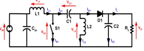
II. SEPIC CONVERTER
respond more gracefully to a short-circuit output), and being capable of true shutdown: when the switch is turned off, its output drops to 0 V, following a fairly hefty transient dump of charge. SEPICs are useful in applications in which a battery voltage can be above and below that of the regulator's intended output. For example, a single lithium ion battery typically discharges from 4.2 volts to 3 volts; if other components require 3.3 volts, then the SEPIC would be effective.
Figure 3. Circuit operation
The schematic diagram for a basic SEPIC is shown in Figure 1. As with other switched mode
power supplies (specifically DC-to-DC
converters), the SEPIC exchanges energy between the capacitors and inductors in order to convert from one voltage to another. The amount of energy exchanged is controlled by switch S1, which is typically a transistor such as a MOSFET. MOSFETs offer much higher input impedance and lower voltage drop than bipolar junction transistors (BJTs), and do not require biasing resistors as MOSFET switching is controlled by differences in voltage rather than a current, as with BJTs).
The control of the boost converter is provided through the PWM signal. The output of the filter which is the control signal is compared with the
reference voltage. The PI controller attempts to minimize the error by adjusting the process control inputs. Then it is compared with the saw-tooth waveform to generate the PWM signal which is fed as gate signal to the IGBT switch. The control circuit regulating the reference voltage Vdcref , which is calculated by the MPPT techniques. Thus the PV array can be controlled by controlling the duty ratio for operating at the maximum power point.
III. CONTROLLER FOR SOLAR INVERTER FOR
INTERFACING GRID
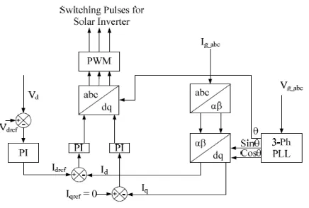
Fig. 4 Block Diagram of Constant Current Controller
Fig. 5 shows the detailed block diagram of the constant current controller for generating the controlled switching pulses for the solar inverter such that the output voltage should be able to interface the grid. The 3-phase Phase Locked Loop calculates the phase angle of the utility grid and also gives the information about the frequency variation. According to the phase angle of the utility grid voltage, the constant current controller is modeled such that the controller is able to generate the switching pulses for solar inverter for tracking the phase of the grid voltage. The 3- phase grid current
Ig_abc is converted into αβ variable using the
Clarke transformation. The variables are transformed into the dq variables. The current Id and Iq are compared with the Idref and Iqref for processing in the PI controller to minimize the errors. These signals are transformed into
3-phase signal using the inverse park’s transform
and then compared with the triangular waveform for generating the PWM switching pulse for the solar inverter. The Vdc and Vdcref is the DC link voltage of the PV array and expected DC voltage of the PV array.
IV. SIMULATION RESULTS:
SIMULINK DESIGN:
GRID SIDE VOLTAGE AND CURRENT:
LOAD SIDE VOLTAGE AND CURRENT:
V. CONCLUSION
For improving the energy efficiency and power quality issues with the increment of the world energy demand, the power generation using the renewable energy source is the only solution.
There are several countries located in the tropical and temperature regions, where the direct solar density may reach up to 1000W/m2. Hence PV system is considered as a primary resource. In this paper, the detailed modeling of grid connected PV generation system is developed. The DC-DC boost converter is used to optimize the PV array output with the closed loop control for keeping the DC bus voltage to be constant. The 2 level 3-phase inverter is converting the DC into the sinusoidal AC voltage. The control of the solar inverter is provided through the constant current controller. This controller tracks the phase and frequency of the utility grid voltage using the Phase- Locked-Loop (PLL) system and generates the switching pulses for the solar inverter. Using this controller the output voltage of the solar inverter and the grid voltage are in phase. Thus the PV system can be integrated to the grid. The simulation results the presented in this paper to validate the grid connected PV system model and the applied control scheme.
III. REFERENCES
[1]. Jabr, R.A.; Džafi´c, I. Solution of DC Railway
Traction Power Flow Systems Including Limited Network Receptivity. IEEE Trans. Power Syst. 2018, 33, 962–969.
[2]. Tian, Z.; Hillmansen, S.; Roberts, C.; Weston, P. Energy evaluation of the power network of a DC railway system with regenerating trains. IET Electr. Syst. Transp. 2015, 6, 41–49.
[4]. Reza, S.; Azah, M.; Shareef, H. Comparative study of effectiveness of different var compensation devices in large-scale power networks. J. Cent. South Univ. 2013, 3, 715–
723.
[5]. Liu, R.; Liu, W.; Cui, H.; Zhang, J.; Liao, J. Capacity optimization design of reactive compensation device in urban rail traction power supply system. In Proceedings of the 2017 IEEE Transportation Electrification Conference and Expo, Chicago, IL, USA, 22–24 June 2017; pp. 1–6.
[6]. Yii, S.T.; Ruay-Nan, W.; Nanming, C. Electric network solutions of DC transit systems with inverting substations. IEEE Trans. Veh. Technol. 1998, 47, 1405–1412.
[7]. Mellitt, B.; Mouneimne, Z.S.; Goodman, C.J. Simulation study of DC transit systems with inverting substations. Electr. Power Appl. 1984, 131, 38–50.
[8]. Suzuki, T. DC power-supply system with inverting substations for traction systems using regenerative brakes. Electr. Power Appl. 1982, 129, 18–26.
[9]. Serrano-Jiménez, D.; Abrahamsson, L.; Castaño-Solís, S.; Sanz-Feito, J. Electrical railway power supply systems: Current situation and future trends. Int. J. Electr. Power Energy Syst. 2017, 92, 181–192.
[10]. Ghaviha, N.; Campillo, J.; Bohlin, M.; Dahlquist, E. Review of Application of Energy Storage Devices in Railway Transportation. Energy Procedia 2017, 105, 4561–4568
Cite this article as :
J. Prince Joshua Gladson, A. Ravielango, "An Efficient Hybrid AC Metro Power Supply System Integrating PV With Grid", International Journal of Scientific Research in Computer Science, Engineering and Information Technology (IJSRCSEIT), ISSN : 2456-3307, Volume 5 Issue 3, pp. 314-321, May-June 2019.
Available at doi :
https://doi.org/10.32628/CSEIT195374