IJEDR1604062 International Journal of Engineering Development and Research (www.ijedr.org) 410
Comparative Analysis of
Microstrip Patch Antennas
of different Feeding Techniques
1
Alamdeep Kaur, 2Amandeep Kaur 1
M.tech student, 2Assistant professor (ECE) 1
GZS College of engineering and technology, Bathinda, Punjab
________________________________________________________________________________________________________
Abstract—Today, Microstrip Patch Antennas are commonly used over conventional antennas because of its low profile,
low cost and ease of manufacturing. In this paper, designed Inverted L Shape Slotted Microstrip Patch Antenna is analyzed. Results of inverted L shaped Microstrip patch antenna designed using microstrip line feeding are compared with the results of P-shaped microstrip patch antenna using Co-axial probe feeding. The design of Inverted L Shape Slotted Microstrip Patch Antenna and the simulation for results are carried out using CST (Computer Simulation Technology) Microwave Studio 2014. Design of Inverted L Shape Slotted Microstrip Patch Antenna is simpler as compared to that of P-shaped microstrip patch antenna and provides improved results. It is also clear from results that the parameters like return loss, bandwidth are improved.
IndexTerms— Microstrip Patch Antenna, Inverted L shape slotted micrrostrip patch antenna, P-shaped microstrip patch
antenna, CST.
________________________________________________________________________________________________________
I.INTRODUCTION
The use of microstrip patch antenna has been much increased these days in various applications such as satellite, spacecraft, mobile radio, wireless communication and missile applications as it fulfills the certain requirements or specifications such as small size, low weight, low cost.[1] Basically Microstrip patch antenna is a low profile antenna with low weight, low fabrication cost, also it is conformal to the surface of objects, easy of fabrication and installation and capable of multiband frequency operations [8] and it is well suited for the applications like WLAN, Wi MAX, Bluetooth etc.[6] Apart from these advantages, the microstrip patch antenna has various limitations, for example, low power handling capacity, low gain, narrow impedance bandwidth, etc.[5] There are various possible methods that can be implemented to enhance the impedance bandwidth of microstrip patch antenna,for example, slotted patch [7], increasing the height of substrate and stacking [1], defected ground surface.[5] However, the implementation of the above listed techniques can make the antenna design complex and sophisticated.[5]
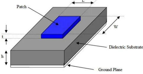
Geometry- The microstrip patch antenna (MPA) has basically four elements which includes a radiating patch, feed line, ground surface and a substrate. The substrate is an intermediate between radiating patch on one side of the substrate and a ground on the other side of substrate as shown in Figure 1.[3] The patch is generally made of conducting material such as copper or gold and it can take any of thepossible shapes, but for simplification of analysis, the patch is generally kept square, rectangular, circular in shape. The radiating patch and the feed lines are generally photo etched on the dielectric substrate.[6]
Figure 1: Structure of a microstrip patch antenna
IJEDR1604062 International Journal of Engineering Development and Research (www.ijedr.org) 411
II.ANTENNADESIGN
Inverted L Shape Slotted microstrip patch antenna
The antenna design has been simulated using the Computer Simulation Technology (CST) Microwave Studio 2014.The material used for substrate is Flame Retardant 4 (FR4) with 4.4 relative constant and it’s thickness is kept 1.57mm. The upper surface has a slotted square shaped radiating patch and the lower surface of the substrate has a defected ground surface. The slotted square shaped patch and defected ground surface are of copper material. [9]
Figure 2(a): Top view of the proposed antenna design [9] Figure 2(b): Bottom view of the proposed antenna design [9] The Figure 2(a) and Figure 2(b) show the top and the bottom view of the antenna design, respectively. An inverted L Shaped slot has been cut on the patch which provides improvement in bandwidth and return loss. The designed antenna is fed directly by the microstrip feed line. The position and size of the microstrip feed line results in impedance matching. The dimensions of substrate, patch, defected ground surface, inverted L shaped slot and slot on the defected ground are given in Table 1. [9]
Table 1 Antenna Dimensions [9]
Antenna Dimensions Value(mm)
Ls 30
Ws 30
Lp 20
Wp 20
Lg 03
Wg1 30
Lf 05
Wf 5.7
L1 02
L2 04
L3 8.75
L4 01
L5 01
W1 12.15
W2 4.25
W3 7.75
W4 03
W5 0.75
W6 13.8
W7 02
W8 03
Lg2 19
IJEDR1604062 International Journal of Engineering Development and Research (www.ijedr.org) 412
P-shaped microstrip patch antenna
The P-shaped microstrip patch antenna is designed for Bluetooth application. The designed antenna resonates at frequency 2.4 GHz with bandwidth of 120 MHz which makes it suitable for Bluetooth applications. The proposed antenna is designed using FR4 substrate with an overall size of 110 mm × 158.5 mm. The antenna is fed by a co-axial probe feeding technique. Top view of P-shaped microstrip patch antenna is shown in Figure 3. The changes in the position of the feed corresponds to the little bit change in the resonant frequency, though there is a remarkable change in return loss. [5]
Figure 3: Top view of P-shaped microstrip patch antenna [5]
III.RESULTSANDDISCUSSIONS
Inverted L Shape Slotted microstrip patch antenna resonates at 3.05 GHz, 4.15 GHz and 5.80 GHz with return loss of -18.32 dB, -34.56 dB and-32.08 dB, respectively with operating impedance bandwidth of 3.13 GHz shown in Figure 4. It has been observed that the value of voltage standing wave ratio (VSWR) of the proposed antenna design is below the maximum acceptable value of 2 for the operating frequency range of 2.91GHz – 6.04GHz. The proposed antenna design can be used for applications such as International Mobile Telecommunication (3.4 GHz -4.2 GHz, 4.4 GHz – 4.9 GHz), Wireless Local Area Network (5.15 GHz – 5.35 GHz, 5.725 GHz – 5.825 GHz) and Worldwide Interoperability for Microwave Access, (3.4 GHz – 3.69 GHz, 5.25 GHz – 5.85 GHz) applications.
Figure 4: Return Loss (S11) plot of antenna design [9]
IJEDR1604062 International Journal of Engineering Development and Research (www.ijedr.org) 413 Figure 5: Return loss (S11) plot of P-shaped microstrip patch antenna [5]
The comparison of the two antennas that is Inverted L Shape Slotted microstrip patch antenna using microstrip feed line and P-shaped microstrip patch antenna using Co-axial probe feed is presented in Table 2.
Table 2 Comparison Table S.No. Parameter Inverted L Shape Slotted microstrip patch antenna
P-shaped microstrip patch antenna
1. Feeding
Technique
Microstrip line feeding Co-axial probe feeding
2. Resonant
frequency
3.05 GHz, 4.15 GHz, 5.80 GHz
2.4 GHz
3. Bandwidth 3.13 GHz (3130 MHZ) 120 MHz
4. Return loss -18.32 dB, -34.56 dB and-32.08 dB
-20 db 5. Applications
covered
IMT, WLAN and WiMAX Bluetooth
IV.CONCLUSION
The Inverted L Shape Slotted microstrip patch antenna has been simulated and designed using Computer Simulation Technology (CST) Microwave Studio 2014. The proposed antenna design employs square shaped patch on the top side of square shaped FR4 material substrate and defected ground surface on the bottom side of substrate. There is an inverted L shaped slot on the top of patch, defected ground surface, a rectangular shaped slot in the defected ground surface and another vertical segment for ground surface on the lower surface of substrate. The results of the proposed antenna shows improved bandwidth, return loss over the P-shaped microstrip patch antenna, comparison of the two designs has been shown in Table II. There is further scope for the bandwidth enhancement and improvement of other parameters with different types of patch and slot shapes.
V.ACKNOWLEDGMENT
I would like to thank my supervisor Er. Amandeep Kaur, Assistant professor, Department of Electronics and Communication Engineering, Giani Zial Singh Campus College of Engineering and Technology, Bathinda, Punjab, India for her supervision and support.
REFERENCES
[1] C.A. Balanis, “Antenna theory analysis and design”, 3rd Edition, New Jersey, John Wiley and Sons, 2005.
[2] N. Mohammed and M. K. Abdelazeez, “Bluetooth/UWB circular patch antenna with dual band notches,” 2013 IEEE Jordan Conference on Applied Electrical Engineering and Computing Technologies (AEECT), pp. 1-4, 2013.
[3] Amarveer Singh and Ekambir Sidhu, “Multiresonant slotted microstrip patch antenna (MPA) design for Bluetooth, IMT, WLAN and WiMAX applications,” American Journal of Engineering Research, vol. 3, Issue 8, pp. 162-170, 2014.
[4] Mehre-eMunir, Ahsan Altaf, Mohammad Hasnain, “Miniaturization of microstrip fractal H-shaped patch antenna using stack configuration for wireless applications,” IEEE 2nd
IJEDR1604062 International Journal of Engineering Development and Research (www.ijedr.org) 414 [5] M. Krishna, M.S. Ganesh, M. Prasanth Kumar Reddy, N.Venkatesh and K. J. Babu, “Design of a novel P-shaped microstrip
patch antenna for Bluetooth applications,” International Conference on Electrical, Electronics, Signals, Communication and Optimizations (EESCO), IEEE, pp.1-3, 2015.
[6] Neha Parmar, Manish Saxena and Krishnkant Nayak, “Review of Microstrip patch antenna for WLAM and WiMAX Application,” Int. Journal of Engineering Research and Applications. Vol. 4, Issue 1( Version 1), 2014.
[7] Atser A. Roy, Joseph M. Môm, Gabriel A. Igwue “Enhancing the Bandwidth of a Microstrip Patch Antenna using Slots Shaped Patch” American Journal of Engineering Research (AJER) e-ISSN : 2320-0847 p-ISSN : 2320-0936 Volume-02, Issue-09, pp-23-30, 2013.
[8] Sweety Goyal, Balraj Singh Sidhu, “A compact slotted microstrip patch antenna for multiband applications,” International Journal of Scientific Research Engineering & Technology (IJSRET), ISSN 2278 – 0882 Volume 3, Issue 7, October 2014. [9] Alamdeep Kaur, Amandeep Kaur, “Inverted L Shape Slotted Micro Strip Patch Antenna for IMT, WiMAX and WLAN
![Table 1 Antenna Dimensions [9]](https://thumb-us.123doks.com/thumbv2/123dok_us/8233262.1373756/2.595.85.513.141.344/table-antenna-dimensions.webp)
![Figure 3: Top view of P-shaped microstrip patch antenna [5]](https://thumb-us.123doks.com/thumbv2/123dok_us/8233262.1373756/3.595.126.497.384.627/figure-view-p-shaped-microstrip-patch-antenna.webp)
![Figure 5: Return loss (S11) plot of P-shaped microstrip patch antenna [5]](https://thumb-us.123doks.com/thumbv2/123dok_us/8233262.1373756/4.595.115.482.265.479/figure-return-loss-plot-shaped-microstrip-patch-antenna.webp)
