International Journal of Nanomedicine
Novel nanostructured biomaterials: implications
for coronary stent thrombosis
Varvara Karagkiozaki1,2
Panagiotis G Karagiannidis1
Nikolaos Kalfagiannis1
Paraskevi Kavatzikidou1
Panagiotis Patsalas3
Despoina Georgiou1
Stergios Logothetidis1
1Lab for Thin Films – Nanosystems
and Nanometrology (LTFN), Physics Department, Aristotle University of Thessaloniki, Thessaloniki, 2AHEPA
Hospital, Aristotle University of Thessaloniki, Thessaloniki,
3Department of Materials Science and
Engineering, University of Ioannina, Ioannina, Epirus, Greece
Correspondence: Stergios Logothetidis Aristotle University of Thessaloniki, Physics Department, Laboratory for Thin Films – Nanosystems and Nanometrology (LTFN), Thessaloniki, GR-54124, Greece Tel +30 2310 998174
Fax +30 2310 998390 Email logot@auth.gr
Background: Nanomedicine has the potential to revolutionize medicine and help clinicians to treat cardiovascular disease through the improvement of stents. Advanced nanomaterials and tools for monitoring cell–material interactions will aid in inhibiting stent thrombosis. Although titanium boron nitride (TiBN), titanium diboride, and carbon nanotube (CNT) thin films are emerging materials in the biomaterial field, the effect of their surface properties on platelet adhesion is relatively unexplored.
Objective and methods: In this study, novel nanomaterials made of amorphous carbon, CNTs, titanium diboride, and TiBN were grown by vacuum deposition techniques to assess their role as potential stent coatings. Platelet response towards the nanostructured surfaces of the samples was analyzed in line with their physicochemical properties. As the stent skeleton is formed mainly of stainless steel, this material was used as reference material. Platelet adhe-sion studies were carried out by atomic force microscopy and scanning electron microscopy observations. A cell viability study was performed to assess the cytocompatibility of all thin film groups for 24 hours with a standard immortalized cell line.
Results: The nanotopographic features of material surface, stoichiometry, and wetting proper-ties were found to be significant factors in dictating platelet behavior and cell viability. The TiBN films with higher nitrogen contents were less thrombogenic compared with the biased carbon films and control. The carbon hybridization in carbon films and hydrophilicity, which were strongly dependent on the deposition process and its parameters, affected the thrombo-genicity potential. The hydrophobic CNT materials with high nanoroughness exhibited less hemocompatibility in comparison with the other classes of materials. All the thin film groups exhibited good cytocompatibility, with the surface roughness and surface free energy influenc-ing the viability of cells.
Keywords: platelets, cell viability, titanium boron nitride, atomic force microscopy, carbon nanotubes
Background
A significant issue in the cardiovascular field is the placement of stents into stenotic arteries to restore blood flow perfusion into myocardial tissues without causing acute or late stent thrombosis and restenosis due to neointimal hyperplasia. Although the higher clinical efficacy of angioplasty with stenting, compared with angioplasty, has
been supported by randomized trials and clinical studies,1,2 stent drawbacks such as
clotting, malpositioning, mechanical rupture, and restenosis still exist. To address the issue of in-stent restenosis, caused almost exclusively by neointimal tissue, drug-eluting stents were developed. This next generation of stents has elicited antiproliferative drugs
Dove
press
O R I G I N A L R E S E A R C H open access to scientific and medical research
Open Access Full Text Article
International Journal of Nanomedicine downloaded from https://www.dovepress.com/ by 118.70.13.36 on 23-Aug-2020
For personal use only.
Number of times this article has been viewed
This article was published in the following Dove Press journal: International Journal of Nanomedicine
leading to a restenosis rate of less than 10% compared with
that of bare metal stents (20%–30%).3
However, there is some evidence that drug-eluting stents may be susceptible to an event known as “late stent thrombosis,” in which the blood clotting inside the stent can
occur one or more years post-stenting.4 Unfortunately, both
the eluted drug agents with cytostatic or cytotoxic effects on the proliferation of the smooth muscle cells on the arte-rial wall, as well as the polymeric stent reservoir for drugs, were found to disrupt the natural healing response of the endothelium. The latter is a living tissue that is antithrom-botic, inhibits leukocyte recruitment, and secrets dilatation factors such as nitric oxide and prostaglandin prostacyclin. Consequently, it is essential that the development of a suit-able stent material/surface takes into consideration control of its physicochemical properties for enhanced cellular endothelial cell growth. Another significant parameter, in order to minimize stent rejection, is the fact that direct contact between stent and blood may trigger activation of platelets and blood coagulation pathways leading to clot formation on
the stent surface and arterial occlusion.5 Thus, the
functional-ity and performance of the biomaterial should be improved to reduce the risk of platelet aggregation/thromboembolism and any complications following the lifelong treatment with anticoagulants.
Recent research has focused on coronary stent surfaces
using nanotechnology strategies.6,7 Carbon- and
titanium-based coatings have attracted much interest due to their good mechanical and biological performance. Until now, carbon coatings have been used for medical implants and titanium-based coatings for medical and surgical tools. Our previous studies on amorphous hydrogenated carbon (a-C:H) thin films with respect to plasma protein adsorption and platelet
adhesion have shown good biocompatibility results.8–10
Thus, in this study, a-C:H films were used as the case study materials and their thrombogenicity and cytocompatibility were compared with the ones of boron nitride (TiBN)-,
tita-nium diboride (TiB2)-, and carbon nanotube (CNT)-based
thin films. Although various studies have focused on the mechanical response, optical, and electron transport
proper-ties of TiBN films,11 their hemocompatibility, as correlated
to their structural characteristics, has not been extensively investigated.
CNTs have emerged as a new and efficient tool for the transport and translocation of therapeutic molecules. CNTs can be functionalized with bioactive peptides, proteins, nucleic acids, and drugs, and used to deliver their cargos
to cells and organs.12 Because functionalized CNTs are not
immunogenic and display low toxicity, they have great
potential for use in the nanomedicine field.13 There is reason
for these materials to be further assessed, since different growth techniques result in specific physicochemical material charac-teristics and specific cell viability behavior. With the same goal in mind, herein, we develop these types of biomaterials with well-defined and tailored properties and assess their feasibility to repel platelets for cardiovascular stent applications.
This work presents original results regarding the throm-bogenicity potential of TiBN- and CNT-based thin films compared with a-C:H and stainless steel (SS) reference materials (SS is a contemporary and widely used material for bare metal stents) through the investigation of human platelet adhesion by atomic force microscopy (AFM). To the best of our knowledge, this is the first thrombogenicity study of CNT composites and TiBN made via AFM implementation. Cell viability studies were also performed in parallel to test the safety of these novel nanomaterials.
Methods and materials
a-C:H thin films
The sputtered a-C:H thin films (100 nm thick) studied in this work were deposited by radio frequency magnetron sputtering on silicon substrates at room temperature (RT). Details about the growth of the films have been described
elsewhere.14 For the growth of a-C:H films, hydrogen (H
2
)-reactive gas was introduced into the vacuum deposition
chamber. The energy of the ions (mainly argon [Ar]+ or H+),
bombarding the growing film surface were varied by applying
a substrate floating bias voltage Vb (+10 V) or a negative Vb
(−40 V) for the a-C:H films, in 5% H2 within plasma.
TiBN and titanium diboride (TiB
2)
thin films
TiBxNy thin films with a thickness of 100 nm were fabricated
employing the magnetron sputtering technique in an unbal-anced configuration. A series of films was grown under the
same negative substrate bias voltage (Vb =−40 V) varying the
nitrogen (N2) flow. The sputtered gas (Ar) pressure was set
constant for all the experiments. Table 1 presents the mate-rial samples, the deposition techniques with the main growth parameters (eg, substrate bias), and the physicochemical properties. The study of the composition of the TiBN samples was realized by X-ray photoelectron spectroscopy in an ultra
high-vacuum chamber (Pb , 10−8 Pa) after sputter etching
with an Ar ion beam. X-ray photoelectron spectroscopy
Dovepress
Karagkiozaki et al
International Journal of Nanomedicine downloaded from https://www.dovepress.com/ by 118.70.13.36 on 23-Aug-2020
Table 1 Materials tested, deposition techniques, main growth parameters, surface nanoroughness, stoichiometry, contact angle, and surface free energy parameters of the samples
Material Deposition technique
Substrate bias (V)
N2 flow (sccm)
Surface roughness (nm)
Contact angle (°)
Surface free energy (mN/m)
a-C:H (5% H2) MS Biased (−40) – 0.3 61 47.2
a-C:H (5% H2) MS Floating – 2.1 63 46
TiBN0.95 Unbalanced MS Biased (−40) 8 1 94.4 26.5
TiB0.9N0.95 Unbalanced MS Biased (−40) 10 2 92.5 27.7
TiB2.13 Unbalanced MS Biased (−40) 0 0.44 40.2 59.3
CNTs Thermal CVD – – 52.3 160 0.3
Stainless steel – – – 74 – –
Abbreviations: a-C:H, amorphous hydrogenated carbon thin films; MS, magnetron sputtering; TiBN, titanium boron nitride; TiB2, titanium diboride; CNTs, carbon
nanotube-based thin films; CVD, chemical vapor deposition.
analysis rendered the stoichiometry of the samples, shown comparatively in Table 1.
CNT-based thin films and SS
The CNT samples were grown by thermal chemical vapor deposition using a diamond-like carbon (DLC) with nickel catalytic layer deposited by pulse laser deposition on a silicon substrate. The nickel was then removed using aqua regis to avoid its toxicity and to manufacture nanopores (with pore
size , 0.1 µm) for promotion of cell growth. SS was used
as reference material.
Characterization of the surface
properties of the thin films
AFM measurements were performed with a SOLVER P47H scanning probe microscope (NT-MDT, Moscow, Russia) in an ambient environment using the tapping mode for imaging
of the surface of the engineered TiBN, TiB2, a-C:H, SS, and
CNT/DLC nanomaterials. Standard silicon cantilevers with
a nominal spring constant of Kc = 1.45–15.1 N/m, resonance
frequency 87–230 kHz, and high aspect ratio conical tips with a curvature radius of 10 nm were used. Scanning electron microscopy (SEM) was also implemented for visualization of the CNT/DLC samples.
The surface energy of the thin films was acquired by contact angle (CA) measurements, which were performed with a CAM200 optical CA and surface tension meter (KSV Instruments, Helsinki, Finland) using the sessile drop
technique. The liquid used was H2O, with a drop volume
of 5 µL and a surface tension of 72.8 mN/m, and the CAs
of each sample were recorded within 5 seconds following placement of droplets onto the thin films. The average CA value was obtained by measuring at five different positions on the same sample. The CAs were converted into surface
energy values employing the relation of Chibowski and
Perea-Carpio.15
Platelet adhesion experiments
Venous blood was drawn from healthy volunteers (who did not take any antiplatelet/antithrombotic drugs) and kept in an anticoagulant with acid citrate tubes. Afterwards, the
blood was centrifuged at 4 × g for 7–10 minutes at RT
to yield platelet-rich plasma (PRP). The thin films were
cleaned with N2 gas flow then they were incubated in
PRP at RT and examined by AFM. The tapping AFM was applied, as this is the optimum mode to avoid soft-platelet
destruction.16 AFM is a type of high-resolution scanning
probe microscopy, with a demonstrated resolution of fractions of a nanometer, ideal for the imaging of living biological samples due to its non-destructive performance. The morphology of the adherent platelets was investigated at 1- and 2-hour intervals and root-mean-square roughness
(Rrms) was used for the evaluation of surface roughness of
the bare films and after platelet adhesion, for ten areas cho-sen at random, to obtain statistical averages of the adherent
platelets (using Student’s t-test).
Cytotoxicity tests
Cell cultureBefore being seeded with the cells, all thin films were washed with ethanol for 5 minutes then dried in air. L929 murine fibro-blasts are an immortalized cell line with tolerance properties against demanding surfaces. The cell line was cultured in Medium 199 (Gibco, Life Technologies, Carlsbad, CA), containing 5% fetal bovine serum, ascorbic acid, and
gen-tamicin at 37°C, in a humidified atmosphere of 5% CO2
in air. For the subculture process, the cell monolayer was washed twice with phosphate-buffered saline and incubated
Dovepress Novel nanomaterials for stent thrombosis
International Journal of Nanomedicine downloaded from https://www.dovepress.com/ by 118.70.13.36 on 23-Aug-2020
with trypsin solution (0.05% trypsin) for 5 minutes at 37°C to detach the cells. Following this, the cells were resuspended in culture medium and cultured for 24 hours in standard tissue culture plates and on the thin films. Cultures were evaluated for cell viability/adhesion for 24 hours (3-(4,5-Dimethylthi-azol-2-yl)-2,5-diphenyltetrazolium bromide [MTT] assay). For comparison purposes, control samples (standard tissue culture plates) were also prepared.
Cell viability assay: MTT assay
The principle of this assay is that live cells, which are meta-bolically active, reduce tetrazolium salts to colored formazan compounds. Therefore, the MTT salt is converted to blue/ purple formazan by living cells. This was used to measure cell viability/proliferation in our study. The culture medium was removed and cultures were incubated with 0.5 mg/mL of MTT solution (in phosphate-buffered saline) for 4 hours. Subsequently, formazan salts were dissolved with isopropanol and the absorbance (in terms of optical density) was measured at 570 nm in an enzyme-linked immunosorbent assay reader (ELx800, BioTek, Winooski, VT). The reference wavelength of 630 nm was also used to measure the same wells and the optical densities obtained were subtracted from the absorbance
of 570 nm to remove any background noise and culture medium obstructions. The data were then optimized to the control to obtain cell viability and cell viability %.
Statistical analysis
Three samples were used for each group of thin films. The
results are shown as the mean ± standard deviation.
Results
Nanoscale surface characterization
and wetting properties of carbon-
and titanium-based thin films
TiBN and TiB2 films
As nanotopography modulates cell behavior, the AFM technique was applied for topography analysis of the nano-materials developed in this work. It was found that all TiBN
and TiB2 films were ultra smooth, having an Rrms below a
nanometer (approximately 0.4 nm). This was attributed to the layer-by-layer growth of the biased coatings induced by the kinetic energy of the sputtered atoms during deposition. Figure 1A shows the AFM topography images of the series of biased TiBN coatings.
nm
µm µm
2,0
5,0 5,0
4,0 4,0
3,0 3,0
2,0 2,0
1,0 1,0
0 0 0
nm
µm µm
1,5
4,5
4,0 4,0
4,5
3,0 3,5
3,0 3,5
2,0 2,5
2,0 2,5
1,0 0,5 1,5
1,0 1,5
0,5 0 0 0
nm
µm
µm 20
2,0 2,0
1,0
0,5 1,5
1,0 1,5
0,5
0 0 0
nm
µm µm
3,0
4,5
4,0 4,0
4,5
3,0 3,5
3,0 3,5
2,0 2,5
2,0 2,5
1,0 0,5 1,5
1,0 1,5
0,5 0 0
nm
µm µm
150
4,5
4,0 4,0
4,5
3,0 3,5
3,0 3,5
2,0 2,5
2,0 2,5
1,0 0,5 1,5
1,0 1,5
0,5 0
nm
µm µm
5
0,2 0,4
0,6 0,8
1,0 1,2
1,4 1,6
1,8
0,4 0,6 0,8 1,0 1,2 1,4 1,6 1,8
0,2 0 0 0
A Biased TiBN0.95 Biased TiB0.9N0.95 Biased TiB2.13
B Biased a-C:H thin films Floating a-C:H thin films C Stainless steel
Figure 1 Atomic force microscopy three-dimensional topography images of: (A) biased titanium (Ti) boron (B) nitride (N) films (TiBN0.95, TiB0.9N0.95, and TiB2.13 films, in
sequence); (B) carbon thin films (biased and floating amorphous hydrogenated carbon [a-C:H] coatings); and (C) stainless steel, as reference material.
Dovepress
Karagkiozaki et al
International Journal of Nanomedicine downloaded from https://www.dovepress.com/ by 118.70.13.36 on 23-Aug-2020
Carbon thin films
The biased a-C:H thin films were atomically smooth. In contrast to biased a-C:H thin films, the floating films have
higher Rrms roughness values (Rrms approximately 2.1 nm)
as the bias voltage application during deposition (floating conditions) gives the potential to the carbon atoms to form aggregates and islands. Figure 1B shows the a-C:H thin films observed by AFM.
SS and CNT/DLC thin films
SS was found to have a high surface roughness of 74 nm (Figure 1C). The CNT/DLC coatings also had a high surface
roughness (Rrms approximately 53 nm) due to the presence
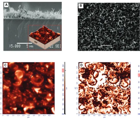
of the nanotubes. Figure 2A and B show SEM images of the CNT/DLC biomaterial. In particular, Figure 2A shows a cross-section SEM image of the nanotubes on the DLC substrate (the inset shows a cartoon schematic detailing the
CNTs deposited onto the DLC) and Figure 2B is an SEM image of the CNTs that shows their spaghetti-like structure. AFM images (Figure 2C and D) revealed that the CNTs were discriminated very well (circled in the figure), having the spaghetti-like form, with the high contrast in phase image (Figure 2D) indicating the formation of nanopores. CA
measurements of TiBN, TiB2, CNT/DLC, and a-C:H thin films
revealed the differences between the wetting properties of the studied films. The CA of the a-C:H films was, 61°–63°; of the TiBN films was, 92.5°–94.4°; of the TiB2 films was, 40.2°; and of the CNT/DLC films was, 160° (Table 1).
Thrombogenicity assessment and
interpretation of the AFM data
Thrombogenesis constitutes a major problem associated with the clinical use of all kinds of prosthetics. Thus, in this study, platelet interactions with the selected biomaterials were
A B
C D
µ
m
µm
4,
5
4,
0
4,0 4,5
3,
0
3,5
3,0 3,5
2,
0
2,5
2,0 2,5
1,
0
0,
5
1,5
1,0 1,5 0,5
0
450,
0
400
500
300
350
200
250 nm
100
50
150
0
73,0
7
90
80
60
40
50 °
20
10
30
0
0
µ
m
µm
4,
5
4,
0
4,0 4,5
3,
0
3,5
3,0 3,5
2,
0
2,5
2,0 2,5
1,
0
0,
5
1,5
1,0 1,5 0,5
0
0
Figure 2 (A) Cross section of a scanning electron microscopy (SEM) image of carbon nanotubes (CNTs) on the diamond-like carbon (DLC) substrate (inset depicts a cartoon
schematic detailing the CNTs deposited onto the DLC substrate). (B) SEM image showing the spaghetti-like structure of the CNTs. (C) Atomic force microscopy (AFM)
topography image of the CNTs (circled), with spaghetti-like formation. (D) AFM phase image of the same CNTs shown in (C) the high contrast is indicative of nanopores.
Dovepress Novel nanomaterials for stent thrombosis
International Journal of Nanomedicine downloaded from https://www.dovepress.com/ by 118.70.13.36 on 23-Aug-2020
investigated by AFM. The advantages of AFM over more con-ventional approaches such as SEM for platelet visualization are related to its atomic-scale resolution along the Z axis; real-time and three-dimensional imaging; non-destruction of the biological samples by the implementation of different AFM modes; no requirement for special preparation of the cells or vacuum conditions that would lead to cellular destruction; and, finally, ability to obtain informative image
cross sections.17
Analysis of the AFM images was based on knowledge concerning the platelet morphological changes due to activation. Platelet shape changes followed a reproducible temporal sequence. The cells in their resting form are
disc shaped, having a width of 0.5–3 µm and height of
120–200 nm. During activation, a cascade of events is triggered leading to the structural alteration of the cells: spherical shape, extension of finger-like projections from the cell periphery, flattening of the cells onto the surface, extension of broad lamellae and formation of pseudonucleus (with a fried-egg appearance) due to the accumulation of the dense and alpha granules into the centre, and elaboration of unique blunt filopodia from cellular periphery based on
new cytoplasmic actin filaments.18 It should be mentioned
that the long, thin filopodia contain bundles of F-actin and the flat lamellae contained an orthogonal array of short
filaments.18 Simultaneously, the activated platelets release
a few chemical compounds from their granules that can induce further activation of other platelets. The next step is the platelet aggregation, an essential procedure for thrombus
formation.19
AFM studies of platelets on TiBN thin films and SS
Figures 3A and B depict the three-dimensional AFM
topo-graphic images of platelets adhered on TiBN0.95 after 1 and
2 hours, respectively. After 1 hour of adhesion, the platelets underwent activation, as highlighted by the pseudonuclei and formation of a few pseudopodia; whereas, after 2 hours, the cells formed aggregates (of a maximum of two cells) with an approximate height of 250 nm (as denoted by the circles). By observing the AFM images of platelets adhering onto
the TiB0.9N0.95 thin films, it was apparent that after 1 hour,
the encircled platelets formed pseudonuclei with distinct pseudopodia (Figure 3C), and after 2 hours, an aggregation of two platelets was formed with the height of 200 nm (Figure 3D). In comparison, after 1 hour, the platelets on SS formed pseudonuclei with pseudopodia (Figure 3E) and, after 2 hours, they aggregated (the height of clusters measured approximately 400 nm [Figure 3F]).
It is of great importance to distinguish fibrin network from platelet pseudopodia when observing the AFM images of platelets adhering onto the samples. As platelet pseudopodia are cell membrane based, their continuity with cytoplasm is their main distinguishing feature. To ensure that the linear structures circled in Figure 3C were platelet pseudopodia and not fibrin networks, an appropriate cross section of the corresponding two-dimensional image was taken (Figure 3G and E).
Concerning the TiB2.13 nanocoatings, the platelets
devel-oped pseudopodia and formed a network even from the first hour of adherence onto the substrate (Figure 4A). After 2 hours, on the same material, the platelet network prevailed, starting to form a thrombus (Figure 4B). AFM is a tool with versatile modes and allows detailed real-time imaging. For example, the cross-section profile along the marked
horizon-tal line in Figure 4C (which depicts platelets on TiB2.13 thin
films) provided information about the platelet dimensions on activation. An activated platelet with pseudopodia, denoted by the circle, had a height of around 100 nm and width of
about 2 µm. To comprehend the differences between the
AFM imaging of platelets onto material interfaces and con-ventional imaging techniques like SEM, Figure 4D and E presents the SEM images of a platelet at an early stage of activation (showing a lack of discoid shape), followed by the development of filopodia at a higher degree of activation. Control experiments in which PRP was imaged on mica were performed and the AFM image of platelets onto mica after incubation for 2 hours is presented in Figure 4F. The AFM
image of one activated platelet (scan size 5 × 5 µm) and the
corresponding cross section along its filopodium are depicted in Figure 4G and H, respectively. As the pseudopodia are temporary cytoplasm-filled projections of the cell wall, their continuity with the cytoplasm, evident in Figure 4G and H, enabled them to be distinguished from the fibrin fibrils.
AFM studies of platelets on CNT/DLC
and a-C:H thin films
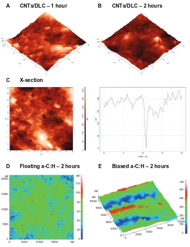
The AFM topography images of platelets on the CNT/ DLC coatings after 1 and 2 hours of observation are shown in Figure 5A and B, respectively. After 1 hour, platelets were at an early stage of activation, as apparant from their pseudonuclei (in white), and after 2 hours they did not form a network. Figure 5C is an AFM topography image of platelets on CNT/DLC thin films after 1 hour of incubation and its cross-section profile along the marked horizontal line. Herein, we observes a nanopore with a depth of approximately 150 nm.
Dovepress
Karagkiozaki et al
International Journal of Nanomedicine downloaded from https://www.dovepress.com/ by 118.70.13.36 on 23-Aug-2020
nm
µm µm
200 120
15 15
20
10 10
5 5
0 A TiBN0.95 – 1 hour
nm
µm µm
200 250
15 15
20
10 10
5 5
0
B TiBN0.95 – 2 hours
nm
µm µm
18 16 0 200
14
10 12
2 4 6 8
µ10m 12 14 16 18
2
0 4 6 8
µ
m
18
16
14
10
12
2
0
4
6
8
25
0
15
0
nm
20
0
0
50
100
18 16 14
10 12
2 4
6 8
0
C TiB0.9N0.95 – 1 hour
nm
µm µm
20 200
15 15
20
10 10
5 5
0
D TiB0.9N0.95 – 2 hours
nm
µm µm
200 250
15 15
20
10 10
5 5
0
E Stainless steel – 1 hour
nm
µm µm
20 400 0
15 15
20
10 10
5 5
0 F
G H
Stainless steel – 2 hours
160
0,0 0,5 1,0 1,5 2,0
Distance (µm)
Height (nm)
2,5 3,0 3,5 180
200 220 240 260 280
Figure 3 Atomic force microscopy topography images of: (A) platelets on titanium (Ti) boron (B) nitride (N)0.95 film after 1 hour of incubation time (scan size 20 × 20 µm);
(B) platelets on TiBN0.95 film after 2 hours of incubation, with a size of 20 × 20 µm (three-dimensional images) – circles indicate the formation of platelet aggregation; (C)
platelets on TiB0.9N0.95 film after 1 hour of incubation; (D) platelets on TiB0.9N0.95 film after 2 hours of incubation time; (E) platelets on stainless steel, as control material,
after 1 hour of cell adhesion; (F) platelets on stainless steel after 2 hours of incubation; (G) platelets on TiB0.9N0.95 film after 1 hour of incubation, corresponding to (C)
(two-dimensional image). (H) Arbitrary cross section of image shown in (G).
Following this, we compared the aforementioned
classes of biomaterials (TiBN, TiB2, CNT/DLC, and SS)
with types of a-C:H thin films that have been described in
detail in our previous works.20–22 After 2 hours’ observation
of platelets on a-C:H floating carbon thin films with a low hydrogen content in plasma during deposition (Figure 5D), it was noticed that the platelets did not aggregate; whereas,
on biased carbon films, after the same time interval, the platelets made clusters that looked like islands (Figure 5E). These qualitative AFM data of the platelet behavior towards the examined biomaterials were presented quantitatively
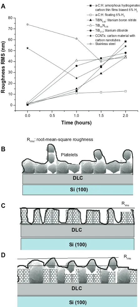
as Rrms measurements of the examined nanomaterials,
after 0, 1 hour, 1.5 hours, and 2 hours of platelet adhesion
(Figure 6A) (P, 0.001).
Dovepress Novel nanomaterials for stent thrombosis
International Journal of Nanomedicine downloaded from https://www.dovepress.com/ by 118.70.13.36 on 23-Aug-2020
nm
µm µm
200 120
15 15
20
10 10
5 5
A TiB2 – 1 hour
nm
µm µm
20 0 150
15 15
20
10 10
5 5
0 0
B TiB2 – 2 hours
10
0
120
14
0
60
nm
80
0
20
40
C X-section
D-E
nm
20 150
15 15
20
10 10
5
0 5
F
G H
Mica – 2 hours
0
0,0 0,5 1,0 1,5 2,0
Distance (µm)
Height (nm)
2,5 3,0 20
40 60 80 100 120 140 160
µ10m 12 14 16 18 20
2
0 4 6 8
µ
m
18
20
16
14
10
12
2
0
4
6
8
250
150 nm
200
0
50
100
20
0 5 10
Distance (µm) Platelets
Height (nm)
15 20
40 60 80 100 120 140 160 180 200 220
µ
m
µm
4,
5
5,0
4,
0
4,0 4,5
3,
0
3,5
3,0 3,5
2,
0
2,5
2,0 2,5
1,
0
0,
5
1,5
1,0 1,5
0,5
0
0
E
D
~20 µm
Figure 4 Atomic force microscopy (AFM) topography images of platelets on titanium (Ti) boron (B)2.13 thin films: (A) after 1 hour of incubation, the cells developed
pseudopodia and formed a network; (B) after 2 hours of incubation, platelet aggregation prevailed; (C) cross section at 16.9 µm, marked with the black circle, an activated
platelet with pseudopodia (left) and, marked with the lines, the platelet and plasma protein aggregated on TiB2.13 thin films (right); (D) scanning electron microscopy (SEM)
image of a platelet at an early stage of activation; (E) SEM image of activated platelets that have lost their discoid shape and begun to develop pseudopodia; (F) AFM image of
platelets obtained on mica after incubation for 2 hours (as control); (G) AFM image of activated platelets with filopodia (scan size of 5 × 5 µm). (H) Arbitrary cross section of an activated platelet along its pseudopodium.
Cell viability assay
Figure 7 shows the cell viability of the different groups of thin films. The best cytocompatibilty behavior was exhibited
by TiB0.9N0.95 (TiBN_2) and the floating a-C:H thin films.
CNT films in direct contact with the murine fibroblasts showed lower cell viability compared with the control group (only cells). The biased a-C:H thin films were the least cyto-compatible thin films. The cytotoxicity results were in full
agreement with the data derived from the thrombogenicity evaluation of the engineered nanomaterials.
Discussion
Nanotechnology advances in
cardiovascular implants
A wide range of vascular prosthetic devices, from stents to artificial heart valves and ventricular assisted devices, have
Dovepress
Karagkiozaki et al
International Journal of Nanomedicine downloaded from https://www.dovepress.com/ by 118.70.13.36 on 23-Aug-2020
nm
µm µm
20 0 250
15 15
20
10 10
5 5
A CNTs/DLC – 1 hour
nm
µm µm
20 300
15 15
20
10 10
5 5
0 0
B CNTs/DLC – 2 hours
C X-section
D Floating a-C:H – 2 hours E Biased a-C:H – 2 hours
µm
18 20 16 14 10 12 2
0 4 6 8
µ
m
18
20
16
14
10
12
2
0
4
6
8
250
300
35
0
150
nm
200
0
50
100
150
nm
20
0
0
50
100
0 5 10
Plane, µm
15 20
0
0 5000 10000 15000 nM 5000
10000 15000 20000nM
0 2000 4000 6000 8000 10000
0
2000 4000 6000
8000 10000 nM
nM nM
0 20 60
40 80 100 120 nM
0 100 300
200 400 500 nM
Figure 5 Atomic force microscopy (AFM) topography images of platelets onto: (A) carbon nanotube (CNT)/diamond-like carbon (DLC) coatings after 1 hour of incubation;
(B) CNT/DLC coatings after 2 hours of incubation, and (C) 2D AFM image of CNT/DLC coatings after 1 hour of incubation (left) and a x-cross section profile at 12 µm
showing a nanopore with a depth of 150nm (right). (D) Amorphous hydrogenated carbon (a-C:H) floating carbon thin films after 2 hours and (E) a-C:H-biased carbon thin
films after 2 hours of adhesion, during which the platelets aggregated.
been implanted worldwide to treat patients that are often expected to live for many years after the procedures. As bio-materials promote surface-induced thrombotic phenomena to some extent, it is essential to evaluate their thrombogenicity. The study of thrombogenetic sequence originates from the platelet response to endothelium damage.
Limited knowledge about the interface phenomena on the border of living and nonliving matter, such as protein adsorp-tion and platelet adhesion, are the theoretical foundaadsorp-tion for the
attempt to develop biocompatible materials. The mechanisms of platelet adhesion constitute key questions in many studies, but despite the enormous research efforts, they are not yet fully understood. When this is translated into the development of coatings for stents, the elucidation of such mechanisms is
necessary to deal with stent drawbacks.23 The elucidation of
such mechanisms can be seen as very necessary.
A wide variety of surface modifications and growth of inorganic stent coatings has been explored, targeting a range
Dovepress Novel nanomaterials for stent thrombosis
International Journal of Nanomedicine downloaded from https://www.dovepress.com/ by 118.70.13.36 on 23-Aug-2020
DLC DLC
Rrms
Rrms Platelets
Rrms: root-mean-square roughness
Si (100) Si (100) DLC
Si (100) 0.0
0 10 20 30 40 50 60 70 80
0.5 1.0
Time (hours)
Roughness RMS (nm)
1.5
a-C:H: amorphous hydrogenated carbon thin films biased 5% H2
a-C:H: floating 5% H2
TiBN0.95: titanium boron nitride
TiB0.9N0.95
TiB2.13: titanium diboride
CCNTs: carbon material with carbon nanotubes Stainless steel
2.0
A
B
C
D
Figure 6 (A) Comparative diagram showing the root-mean-square roughness (Rrms)
values of the engineered nanomaterials, after 0, 1 hour, 1.5 hours, and 2 hours of platelet
adhesion. (B) Schematic illustration of a time-dependent increase in surface roughness
(Rrms) depending on platelet adhesion onto bare carbon and titanium thin films of low
nanoroughness. Schematic representations of (C) an increase in Rrms on bare carbon
nanotube (CNT)/diamond-like carbon (DLC) nanocoatings due to CNT bundles and
(D) a decrease in Rrms during platelet aggregation on the CNT/DLC substrates.
of objectives such as reduced metal ion release, avoidance of surface thrombogenicity, and texturing to promote
endothelialization.24 Nanotechnology provides material
manufacturers with the ability to fabricate and control mate-rial properties. After decreasing the size of matemate-rials to the nanoscale, a dramatically increased surface area and surface
area to volume ratio are produced that can lead to superior physical properties (ie, mechanical, electrical, and optical, etc). Nanomaterials with such excellent properties have been extensively investigated in a wide range of biomedical
applications, such as vascular stents.25 This research has been
fostered by the facts that the vascular walls possess numer-ous nanostructured features (eg, due to the presence of col-lagen and elastin in the vascular endothelial cellular matrix) and that nanomaterials mimic the endothelium structure. Choudhary et al reported that vascular cell adhesion and pro-liferation were greatly improved on nanostructured titanium
compared with conventional titanium.25 The nanotechnology
strategies deal not only with the enhancement of stent endothe-lialization but also with the avoidance of stent thrombosis. Much research demonstrates the thrombogenicity assessment of various classes of nanomaterials. For example, Maguire et al reported the reduced thrombogenicity of amorphous
DLC materials for stents and medical guide wires.26
Nanomaterial properties dictate
platelet response
This study focused on the influence of surface nanotopog-raphy and physicochemical characteristics of carbon- and titanium-based biomaterials on cell viability and, especially, on platelet structural changes, as an index of activation. Thrombogenic assessment of the examined materials will lead to the selection of those that are more thromboprotec-tive and thus may be used as an additional layer to coat the existing stent metal platforms. The ultimate goal is to reduce stent thrombosis.
It is well described that implanted materials are imme-diately coated with proteins from blood and interstitial fluids, and it is through this adsorbed layer that cells sense foreign surfaces. In previous studies, we have developed a methodology to study the possibility of thrombus formation during material–protein interactions, the optical proper-ties of the adsorbed plasma proteins, and their adsorption
mechanisms.10,14 Ex-situ spectroscopic ellipsometry
mea-surements in the energy region of 1.5–6.5 eV of human albumin and fibrinogen adsorbed onto a-C:H thin films and AFM studies have shown that the carbon hybridization, configuration, and hydrogen content determine surface
properties, protein adsorption, and platelet behavior.9,10,27
The sp3 fractions of the engineered a-C:H thin films in the
present study were about 40%–44%, which has been found to be the optimum value in terms of the hemocompatibility
of carbon-based thin films (Logothetidis et al14). In this study,
the low content of hydrogen in plasma and the absence of ion
Dovepress
Karagkiozaki et al
International Journal of Nanomedicine downloaded from https://www.dovepress.com/ by 118.70.13.36 on 23-Aug-2020
120
100
80
60
40
20
0
Only cells TiB2 TiBN_1 TiBN_2
Groups
Cell viability (%)
CNTS a-C:H_B a-C:H_F
Figure 7 Comparative diagram showing the L929 fibroblasts viability in direct contact with the engineered materials for 24 hours under static conditions.
Abbreviations: a-C:H, amorphous hydrogenated carbon thin films; a-C:H_B, biased amorphous hydrogenated carbon thin films; a-C:H_F, floating amorphous hydrogenated carbon thin films; TiBN, titanium boron nitride; TiBN_1, TiBN0.95; TiBN_2, TiB0.9N0.95; TiB2, titanium diboride; CNTs, carbon nanomaterial with carbon nanotubes;
MTT, 3-(4,5-Dimethylthiazol-2-yl)-2,5-diphenyltetrazolium bromide.
bombardment during deposition of the carbon films lead to surface nanotopography that repelled platelets. The surface nanoroughness of the floating a-C:H thin film of approxi-mately 2 nm was found to influence platelet response. In contrast, the atomically smoother a-C:H films (biased) were found to be more thrombogenic and less cytocompatible. These slight variations in the surface roughness of the two types of carbon materials are to be expected, as in vivo cells respond to textured cues in the extracellular matrix that contain pores, protrusions, pits, and fibers in the length scale
of 5–200 nm.28
Upon adhesion to a substrate, the cell probes its environ-ment and moves using nanometer-scale structures such as filopodia and lamellipodia. Filopodia probe the environment around the cell and their ends serve as anchor points for
movement.29 As these structures have sizes in the nanometer
range (eg, platelet filopodia have a tip diameter of 120 nm, as
measured by AFM9), it is likely that they will be influenced
by nanotopography. These observations can also be explained by the fact that the nature of the biomaterial surface is a sig-nificant factor in the protein adsorption that mediates platelet interactions. It is fully accepted that the presence of proteins adsorbed on the artificial surface play a crucial role in
mediat-ing the initial interactions of platelets with the surface, and the composition of the synthetic surface is a key determinant
in the rate and nature of the protein adsorbed.30 Our previous
studies have shown that human albumin is adsorbed more easily on floating carbon thin films with nanoroughness and a low hydrogen content in plasma. In contrast, fibrinogen is favorably adsorbed into biased carbon coatings in comparison
to floating ones.8 The electrical properties of the carbon thin
films have been found to strongly affect the reactions of the
electrically negative platelets.31
The TiBN films have a large number of uses in the cutting
and decorative applications.32 They exhibit low corrosion
current density in acid environments, high oxidation resis-tance, and excellent abrasive wear resistance accompanied
with high thermal stability.33 The lack of studies on their
biomedical use gave us the stimulus for their thrombogenicity analysis. The biased TiBN films were found to possess bet-ter biological properties compared with biased carbon films. Although the biased TiBN and carbon films are ultra smooth, due to their layer-by-layer growth, it can be noted that in these classes of materials, the stoichiometry is more impor-tant than the nanotopography. It is known that the surface chemistry on the nanometer scale can be a deciding factor
Dovepress Novel nanomaterials for stent thrombosis
International Journal of Nanomedicine downloaded from https://www.dovepress.com/ by 118.70.13.36 on 23-Aug-2020
in the recruitment of specific cell membrane integrins acting as cell attachment molecules. Upon attachment to a surface, the integrin receptors cluster together and recruit cytoplasmic
proteins to form the focal contacts.29 In the case of platelets,
glycoprotein IIb/IIIa (also known as integrin α2bβ3) interacts
with the amino acid sequence arginyl-glycyl-aspartyl-serine (RGDS) present on several adhesive proteins (fibrinogen, von Willebrand factor, and fibronectin) and the glycoprotein Ib-IX complex interacts with the insoluble von Willebrand
factor bound to the subendothelium.19
The AFM studies revealed that when the nitrogen content of the TiBN films increases, their thrombogenicity is reduced while their cytocompatibility increases in comparison with the control material. This can be justified partially by the
albumin adsorption that is enhanced on these surfaces.34 The
addition of nitrogen into the coating is an interesting aspect that has not been widely addressed. Endothelium-derived nitric oxide is known to be important in regulating endothelial function, helping suppress platelet aggregation, and cellular adhesion to the endothelium, and even in inhibiting smooth muscle cell proliferation. A titanium-nitride oxide coating has been developed for stent applications and its effects are
promising.35
Due to their specific structure/texture and properties, CNTs are emerging materials that may play a significant
role in the development of carbon materials for medicine.36
However, it must be noted that the biocompatibility of CNTs is still in question and is being actively studied by different
research groups.37,38 In our study, it was found that coatings
composed of CNTs exhibit less hemocompatibility than both TiBN and the reference material. The AFM images showed nanostructures on the surface of the CNTs based coatings attributed to the presence of CNTs and nanopores due to the special preparation of the films. As the cells are able to respond to nanostructures, these surface irregularities may have a significant impact on the organization of focal adhesions formed in platelets, either by disrupting their
elongation or by inducing specific integrin recruitment.29
The changes in platelet morphology, such as stretching on the nanogrooves between the CNTs, can result in differential stress that is not present when the cell is grown on a flat surface. This mechano-transduction process can transmit information from outside into the cell and can induce changes in cell behavior.
The high nanoroughness of the CNT/DLC thin films, which reaches 52 nm, is not favorable to the inhibition of platelet aggregation. This finding is in agreement with data from a study on the influence of surface roughness on the
activation of coagulation and platelet adhesion on continuous
flow blood pumps.39 In their study, Linneweber et al showed
that surface roughness greater than 50 nm stimulates platelet adhesion and fibrinogen adsorption, indicating a reduc-tion in anti-thrombogenicity in devices with rougher metal
finishes.39
What is remarkable is the fact that both carbon- (without nanotubes) and titanium-based films showed a
time-dependant increase in surface roughness (Rrms) depending
on platelet adhesion and aggregation onto the substrates.
In contrast, the bare CNT/DLC nanocoatings had high Rrms
values due to the CNT bundles, but this then decreased because of the platelet adhesion during time. A schematic illustration of this phenomenon is depicted in Figure 6B–D. Following the same trend, the roughness of the SS material was reduced, owing to platelet aggregation, after 1.5 hours of AFM observation and then, within 2 hours, it increased slightly again.
The correlation between surface wettability and
throm-bogenicity has been confirmed by several studies.40,41 The
wettability measurements in the present study show that the surface free energy of the materials and their hydrophi-licity/hydrophobicity dictate platelet response. The CNT/ DLC and TiBN thin films were found to be hydrophobic,
whereas the CAs of the a-C:H and TiB2 samples indicated
their hydrophilic nature. The CNTs/DLC films were more hydrophobic in comparison with the TiBN thin films. No statistical difference between the measured CAs of the TiBN classes was found, and there was no obvious effect of this on the thrombogenicity properties. In these materi-als, surface chemistry seems to play a key role in platelet behavior. The good hemocompatible behavior of the a-C:H materials can be partially attributed to their hydrophilicity, as most hydrophilic films exhibited a better protein to surface
concentration ratio.34 The surface of the floating a-C:H thin
films may mimic the properties of endothelial cells lining blood vessels, which have a net negative charge and are also hydrophilic. These two properties have been postulated to
decrease the attachment of platelets.41 Overall, the surface
chemistry, nanotopographical features, and wetting properties of the examined materials influence the variability of platelet response when they come into contact.
Hence, cell activation and motility are ultimately mechan-ical phenomena, but little is known about the mechanmechan-ical and
physical properties of moving cells.42 A few AFM studies
of time-dependent structural changes, cell migration, and the associated changes in mechanical properties have been
reported for platelets.43 Fritz et al43 demonstrated that platelets
Dovepress
Karagkiozaki et al
International Journal of Nanomedicine downloaded from https://www.dovepress.com/ by 118.70.13.36 on 23-Aug-2020
that have bound to the surface but remain inactivated can be scanned by AFM at low forces with no noticeable time-dependent changes in shape. However, scanning at higher
forces promotes their activation. Radmacher et al44 reported
that the elastic modulus values of activated platelets were in the range of 1–50 kPa, as measured by force mapping techniques. Further, a recent study shown that platelet con-traction reaches a steady state after 25 minutes, displaying
total forces of ∼34 nN.45
Taking into account the mechanical aspects of cell motility, a limitation of the present study is that the platelet experiments were performed under in vitro conditions with-out the influence of blood flow and shear stress on platelet activation. Moreover, in humans, the complex coagulation system and the interplay between the plasma proteins and blood cells with the vascular biomaterials result in difficul-ties in comprehending their biocompatibility. Future studies will address this issue to enhance our knowledge about how platelets interact with stent nanomaterials in atherosclerotic human arteries.
Conclusion
This work presents strong evidence that the surface chemis-try, nanostructure, and wetting properties are the parameters that greatly determine platelet adhesion and the cytocompat-ibility behavior of a surface. In this work, a range of nano-materials, ranging from a:C:H and CNT/DLC thin films to
TiBN and TiB2 thin films was developed, characterized, and
studied for potential application as stent coatings.
The carbon hybridization, hydrogen content, and configu-ration of carbon films (grown by sputtering technique) were found to determine their physicochemical and biological properties. The low content of hydrogen in plasma and the absence of ion bombardment during deposition of the carbon films led to surface nanotopography that inhibited platelet aggregation. Their hydrophilic nature and slight nanorough-ness favorably influenced platelet behavior. In contrast, the atomically smooth carbon nanocoatings (biased) had the opposite effect.
The surface chemistry of the TiBN thin films, especially the higher nitrogen content, dictated the inhibition of clot formation. The AFM results indicated that the biased TiBN films were less thrombogenic compared with biased carbon films. CNT coatings, as grown by chemical vapor deposition, were found to be less hemocompatible than the controls. Their high nanoroughness due to CNT bundles and hydropho-bicity played a significant role in their low thromboprotectivity. The nanomaterials exhibited strong differences in terms of
wettability. The surface free energy affected the thrombo-genic properties, since good hemocompatible behavior was observed in the materials with higher surface free energy, such as the a-C:H films.
Overall, the results indicate that nanostructure modifi-cations, stoichiometry, and hydrophilicity of biomaterial surfaces could elicit the desired platelet response and cyto-compatibility, which could be significant in the development of blood-contacting materials like stent coatings.
Acknowledgment
The authors would like to thank E Diamanti and D Gourni for their contribution to the preparation of the CNTs/DLC. They would also like to acknowledge the project entitled ‘Exploitation of research results on Nanotechnology’ for its financial support.
Disclosure
The authors declare no conflicts of interest in this work.
References
1. Colombo A, Iakovou I. Drug-eluting stents: the new gold standard for
percutaneous coronary revascularisation. Eur Heart J. 2004;25(11):
895–897.
2. Smith EJ, Jain KA, Rothman MT. New developments in coronary stent
technology. J Interv Cardiol. 2006;19(6):493–499.
3. Stone GW, Moses JW, Ellis SG, et al. Safety and efficacy of
sirolimus- and paclitaxel-eluting coronary stents. N Engl J Med.
2007;356(10):998–1008.
4. Bavry AA, Kumbhani DJ, Helton TJ, Borek PP, Mood GR, Bhatt DL. Late thrombosis of drug-eluting stents: a meta-analysis of randomized
clinical trials. Am J Med. 2006;119(12):1056–1061.
5. Hara H, Nakamura M, Palmaz JC, Schwartz RS. Role of stent design
and coatings on restenosis and thrombosis. Adv Drug Deliv Rev.
2006;58(3):377–386.
6. Zhang L, Webster TJ. Nanotechnology and nanomaterials: promises
for improved tissue regeneration. Nano Today. 2009;4(1):66–80.
7. Nakano K, Egashira K, Masuda S, et al. Formulation of nanoparticle-eluting stents by a cationic electrodeposition coating technology: efficient nano-drug delivery via bioabsorbable polymeric
nanoparticle-eluting stents in porcine coronary arteries. JACC Cardiovasc Interv.
2009;2(4):277–283.
8. Logothetidis S. Haemocompatibility of carbon based thin films. Diam
Relat Mater. 2007;16(10):1847–1857.
9. Karagkiozaki VC, Logothetidis SD, Kassavetis SN, Giannoglou GD. Nanomedicine for the reduction of the thrombogenicity of stent coatings.
Int J Nanomedicine. 2010;5:239–248.
10. Lousinian S, Logothetidis S, Laskarakis A, Gioti M. Haemocompatibility of amorphous hydrogenated carbon thin films, optical properties and
adsorption mechanisms of blood plasma proteins. Biomol Eng.
2007;24(1):107–112.
11. García-González L, Hernández-Torres J, García-Ramírez PJ, et al. Struc-ture and mechanical properties of TiBN coatings fabricated by dc reactive
sputtering technique. J Mater Process Technol. 2007;186(1–3): 362–366.
12. Yang Z, Zhang Y, Yang Y, et al. Pharmacological and toxicological target organelles and safe use of single-walled carbon nanotubes as drug
carri-ers in treating Alzheimer disease. Nanomedicine. 2010;6(3): 427–441.
13. Ménard-Moyon C, Kostarelos K, Prato M, Bianco A. Functionalized carbon nanotubes for probing and modulating molecular functions.
J Chem Biol. 2010;17(2):107–115.
Dovepress Novel nanomaterials for stent thrombosis
International Journal of Nanomedicine downloaded from https://www.dovepress.com/ by 118.70.13.36 on 23-Aug-2020
International Journal of Nanomedicine
Publish your work in this journal
Submit your manuscript here: http://www.dovepress.com/international-journal-of-nanomedicine-journal
The International Journal of Nanomedicine is an international, peer-reviewed journal focusing on the application of nanotechnology in diagnostics, therapeutics, and drug delivery systems throughout the biomedical field. This journal is indexed on PubMed Central, MedLine, CAS, SciSearch®, Current Contents®/Clinical Medicine,
Journal Citation Reports/Science Edition, EMBase, Scopus and the Elsevier Bibliographic databases. The manuscript management system is completely online and includes a very quick and fair peer-review system, which is all easy to use. Visit http://www.dovepress.com/ testimonials.php to read real quotes from published authors. 14. Logothetidis S, Gioti M, Lousinian S, Fotiadou S. Haemocompatibility
studies on carbon-based thin films by ellipsometry. Thin Solid Films.
2005;482(1–2):126–132.
15. Chibowski E, Perea-Carpio R. Problems of contact angle and solid
sur-face free energy determination. Adv Colloid Interface Sci. 2002;98(2):
245–264.
16. Müller DJ, Anderson K. Biomolecular imaging using atomic force
microscopy. Trends Biotechnol. 2002;20(8):S45–S49.
17. Allison DP, Mortensen NP, Sullivan CJ, Doktycz MJ. Atomic force
microscopy of biological samples. Wiley Interdiscip Rev Nanomed
Nanobiotechnol. 2010;2(6):618–634.
18. Karagkiozaki V, Logothetidis S, Kalfagiannis N, Lousinian S, Giannoglou G. Atomic force microscopy probing platelet activation behavior on titanium nitride nanocoatings for biomedical applications.
Nanomedicine. 2009;5(1):64–72.
19. Hartwig JH. Platelet structure. In: Michelson AD, editor. Platelets.
San Diego, CA: Academic Press; 2002:37–45.
20. Karagkiozaki V, Logothetidis S, Giannoglou G. Advances in stent
coat-ing technology via nanotechnology tools and process. Eur J Nanomed.
2008;1(1):24–28.
21. Karagkiozaki V, Logothetidis S, Kassavetis S, Lousinian S. Nanoscale characterization of biological and mechanical profile of carbon stent
nanocoatings. Eur J Nanomed. 2009;2(1):14–21.
22. Karagkiozaki V, Logothetidis S, Laskarakis A, Giannoglou G, Lousinian S. AFM study of the thrombogenicity of carbon-based
coat-ings for cardiovascular applications. Mater Sci Eng B. 2008;152(1–3):
16–21.
23. Joner M, Finn AV, Farb A, et al. Pathology of drug-eluting stents in
humans: delayed healing and late thrombotic risk. J Am Coll Cardiol.
2006;48(1):193–202.
24. O’Brien B, Carroll W. The evolution of cardiovascular stent materials
and surfaces in response to clinical drivers: a review. Acta Biomater.
2009;5(4):945–958.
25. Choudhary S, Berhe M, Haberstroh KM, Webster TJ. Increased endothelial and vascular smooth muscle cell adhesion on nanostructured
titanium and CoCrMo. Int J Nanomed. 2006;1(1):41–49.
26. Maguire PD, McLaughlin JA, Okpalugo TI, et al. Mechanical stability, corrosion performance and bioresponse of amorphous
diamond-like carbon for medical stents and guidewires. Diam Relat Mater.
2005;14(8):1277–1288.
27. Mitsakakis K, Lousinian S, Logothetidis S. Early stages of human
plasma proteins adsorption probed by Atomic Force Microscope. Biomol
Eng. 2007;24(1):119–124.
28. Lord MS, Foss M, Besenbacher F. Influence of nanoscale surface
topography on protein adsorption and cellular response. Nano Today.
2010;5(1):66–78.
29. Anselme K, Davidson P, Popa AM, Giazzon M, Liley M, Ploux L. The interaction of cells and bacteria with surfaces structured at the nanometre
scale. Acta Biomater. 2010;6(10):824–846.
30. Yang P, Huang N, Leng YX, et al. Activation of platelets adhered on amorphous hydrogenated carbon (a-C:H) films synthesized by
plasma immersion ion implantation-deposition (PIII-D). Biomaterials.
2003;24(17):2821–2829.
31. Karagkiozaki V, Logothetidis S, Lousinian S, Giannoglou G. Impact of surface electric properties of carbon-based thin films on platelets
activa-tion for nano-medical and nano-sensing applicaactiva-tions. Int J Nanomed.
2008;3(4):461–469.
32. Holzschuh H. Deposition of Ti–B–N (single and multilayer) and Zr–B–N coatings by chemical vapor deposition techniques on cutting
tools. Thin Solid Films. 2004;469–470:92–98.
33. Aouadi SM, Debessai M, Namavar F, Wong KC, Mitchell KA. Titanium boron nitride films grown by ion beam assisted deposition: chemical and
optical characterization. Surf Coat Technol. 2004;183(2–3):369–377.
34. Lousinian S, Kalfagiannis N, Logothetidis S. Albumin and fibrinogen
adsorption on boron nitride and carbon-based thin films. Mater Sci Eng B.
2008;152(1–3):12–15.
35. Vallance P, Chan N. Endothelial function and nitric oxide: clinical
relevance. Heart. 2001;85(3):342–350.
36. Usui Y, Aoki K, Narita N, et al. Carbon nanotubes with high
bone-tissue compatibility and bone-formation acceleration effects. Small.
2008;4(2):240–246.
37. Kim JY, Khang D, Lee JE, Webster TJ. Decreased macrophage density
on carbon nanotube patterns on polycarbonate urethane. J Biomed Mater
Res A. 2009;8(2):419–426.
38. Muller J, Huaux F, Fonseca A, et al. Structural defects play a major role in the acute lung toxicity of multiwall carbon nanotubes: toxicological
aspects. Chem Res Toxicol. 2008;21(9):1698–1705.
39. Linneweber J, Dohmen PM, Kertzscher U, Affeld K, Nosé Y, Konertz W. The effect of surface roughness on activation of the
coagula-tion system and platelet adhesion in rotary blood pumps. Artif Organs.
2007;31(5):345–351.
40. Xu LC, Siedlecki CA. Effects of surface wettability and contact time
on protein adhesion to biomaterial surfaces. Biomaterials. 2007;
28(22):3273–3283.
41. Tulloch AW, Chun Y, Levi DS, et al. Super hydrophilic thin film nitinol demonstrates reduced platelet adhesion compared with commercially
available endograft materials. J Surg Res. 2011;171(1):317–322.
42. Kuznetsova TG, Starodubtseva MN, Yegorenkov NI, Chizhik SA,
Zhdanov RI. Atomic force microscopy probing of cell elasticity. Micron.
2007;38(8):824–833.
43. Fritz M, Radmacher M, Gaub HE. Granula motion and membrane spreading during activation of human platelets imaged by atomic force
microscopy. Biophys J. 1994;66(5):1328–1334.
44. Radmacher M, Fritz M, Kacher M, Cleveland P, Hansma, K. Measuring the viscoelastic properties of human platelets with the atomic force
microscope. Biophys J. 1996;70(1):556–567.
45. Henriques SS, Sandmann R, Strate A, Köster S. Force field evolution
during human blood platelet activation. J Cell Sci. 2012. Epub May 11.
Dovepress
Dove
press
Karagkiozaki et al
International Journal of Nanomedicine downloaded from https://www.dovepress.com/ by 118.70.13.36 on 23-Aug-2020

![Figure 1 Atomic force microscopy three-dimensional topography images of: (A) biased titanium (Ti) boron (B) nitride (N) films (TiBN0.95, TiB0.9N0.95, and TiB2.13 films, in sequence); (B) carbon thin films (biased and floating amorphous hydrogenated carbon [a-C:H] coatings); and (C) stainless steel, as reference material.](https://thumb-us.123doks.com/thumbv2/123dok_us/8326566.1380420/4.612.64.529.389.694/microscopy-dimensional-topography-amorphous-hydrogenated-coatings-stainless-reference.webp)