IJEDR1602049
International Journal of Engineering Development and Research (www.ijedr.org)275
Improving The Head And Efficiency of A Pump
Mehta Mehul Pravinchandra Assistant Professor
Master of Engineering in subject of Thermal Engineering, Gujarat Technology University Vadodara Institute of Engineering, at kotambi, on Halol highway road, Vadodara, Gujarat -390014
________________________________________________________________________________________________________
Abstract - Pump widely used in agricultural irrigation, flood control, urban water supply, the cooling water system of power plant, Dairies, Firefighting systems, cooling water circulating systems and other fields. When the flow passes through the blades, it is always complicated to understand the behaviour of the flow. The losses created like impeller entry losses, leakage loss, and impeller losses always decreases the efficiency of the pump.Hence, by reducing the losses of pump, Performance of pump has been improved. To improve the head and efficiency of pump, various analytical softwares are available which gives the information about complex flow inside the impeller. The models of the pump impeller made in solidworks 2009. Performance analysis has been carried out by experimental and ANSYS CFX software.For the given problem backward blade pump with8 number of blade is selected. Experimental readings have been collected from company and software analysis results compared. Now, the parameters like inlet blade angle, outlet blade angle, number of blades have been changed for analysis. From the results obtained by changed geometry has been optimized by Taguchi method. Performance Improved has been seen in the head and efficiency of the pump.
Key words - Pump, Computational Fluid Dynamics (CFD) analysis, and Optimization with taguchi method.
________________________________________________________________________________________________________
I.INTRODUCTION
A pump is a device used to moveliquids by mechanical action. Pumps can be classified into three major groups according to the method they use to move the fluid: direct lift, displacement, and gravity pumps. A wide variety of pump types have been constructed and used in many different applications in industry. Pumps must have a mechanism which operates them, and consume energy to perform mechanical work by moving the fluid. The activating mechanism is often reciprocating or rotary. Pumps may be operated in many ways, including manual operation, electricity, an engine of some type, or wind action.
Mixed Flow Pump:-
Main Parts of A Pump
‒ Impeller blade ‒ Electric motor ‒ Stuffing box ‒ Coupling ‒ Head shaft
Application
Pumps are found in many applications. Single stage pumps are used for drainage, sewage pumping, general industrial pumping and slurry pumping. They are also popular with aquarium filters. Multiple stage submersible pumps are typically lowered down a borehole and used for water abstraction, water wells and in oil wells.
Problem Of Definition
‒ I obtain information with the research paper A. Manivannan related my topic. Which is so helpful to achive my final result.
‒ The Experimental Data collected from the A. Manivannan research paper to be say that low head and efficiency that are the major problem of pump.
‒ There are different types of losses occurs in this pump like friction losses, pressure drop, impeller losses. ‒ Also optimization the performance of Existing pump impeller by Taguchi method.
II.LITERATURE SURVEY
IJEDR1602049
International Journal of Engineering Development and Research (www.ijedr.org)276
Table 1- Vane angle of modified impellersKiran patel (2008) et al, in his studied of CFD analysis of pump derived that the head predicted by CFD analysis is higher than the test result at rated point. It also concluded that power predicted by CFD analysis is higher at rated point to compare with the test result.
Fig1:Head versus Capacity Curve Fig2:Efficiency versus Capacity Curve
Power predicted by CFD analysis is 5 to 10% higher at rated point. The volumetric efficiency is determined. Pump efficiency considering disc friction loss and leakage-loss was predicted and it was found within +5% ranges, at duty point. Efficiency predicted by CFD analysis is higher than the test result. Leakage-loss was predicted using. Efficiency was improved by 1% after matching stator angle and changing hub curve profile. Stator blade loading at hub and shroud has improved. [1]
Mandar TABIB*(2009)et al,in his study of CFD analysis of pump derived that the computational simulation of the mixed flowpump impeller was implemented.A CFD code, the ANSYS® CFX® 12.1, was used to obtain the head and pressure, velocity streamlines. The analysis results show the head of 7.45m and the head achieved by the experimental work in industries was 8.08 m.The efficiency find by experimental result was53.27 % and by CFD analysis 49.6 %.Because in CFD analysisthere is no influence from the diffuser, so the friction lossesare smaller, affecting the pressure fields and increasing thehead values. This fact represents the necessity to introducethe friction losses due to coupling between the diffuser andimpeller.Result shows pressure in the impeller channelsincreases from the entrance to the discharge in successiveranges. [3]
III.FUNCTION OF WORK
A survey of the previous research work has shown that various authors have carried out investigations under completely different conditions. I have selected backward-swept pump impeller having 8 number of blade. I have collects experimental reading from the research paper and analysis of pump impeller in software.First, I have completedmodelling and meshing of pump impeller and I have been completed CFD analysis of pump.Then experimental readings from company and analysis results from ANSYS CFX software compared.The parameter like inlet and outlet blade angle, number of impeller blade havebeen changed for analysis.So I have been get different result for different parameter. The results of different parameter pump impeller are optimized by Taguchi method. Finally, Results of Taguchi method have been achieved maximum head, power consume and efficiency.On the basis of optimization, the final conclusion has been predicted.
IV.METHODOLOGY
Table 2: DATA COLLECTED FROM RESEARCH PAPER
Sr. no. Parameter Size
1 Blade inlet angle (α) 40˚
2 Blade outlet angle (β) 29˚
3 Number of blade 8
4 Blade thickness (t) 3mm
5 Impeller inlet Diameter (Di) 50mm
6 Impeller outlet Diameter (Do) 112mm
7 Impeller Rotation speed 2800rpm
8 Casing inlet diameter NOT POSSIBLE BECAUSE FLUID IS ENTER FROM IMPELLER
9 Casing outlet diameter 27.75 mm
10 Casing width 92 mm
Boundary Condition
Table 3: Boundary Condition
Inlet boundary condition Pressure 1.948 x 10
4 pa
IJEDR1602049
International Journal of Engineering Development and Research (www.ijedr.org)277
Temperature 298 k
Mass flow rate 7 kg/sec
Outlet Boundary condition
Pressure 1.382 x 10⁵ pa
Velocity 23.162 m/sec
Temperature 305 k
Mass flow rate 7 kg/sec
Wall Boundary condition
Heat transfer adiabatic
Mass and Momentum No slip well
Wall Roughness Smooth wall
Wall motion Rotating
Blade Boundary condition
Heat transfer adiabatic
Mass and Momentum No slip well
Wall Roughness Smooth wall
Surface Roughness on blade 10micron
Heat transfer Model Total Energy
Turbulence Model K-Epsilon
Fluid Water (1000 Density)
Element Tetrahedral Element
Table 4- CHANGED PARAMETERS OF IMPELLER
Sr. no. Parameters Existing data Case-1 Case-2
1 Number of blade 8 6 10
2 Blade inlet angle 40˚ 38˚ 42˚
3 Blade outlet angle 29˚ 27˚ 31˚
V.MODELLING OF PUMP
Fig 3: 3D Model of pump impeller
Our CFD Analysis method is Cavity Patten so we have to create Cavity model of above impeller. Save below Cavity model in *. IGES Format for Importing into ANSYS Workbench Mesh Module for Meshing.
Cavity Model of Impeller
Fig 4-Create Cavity Model of pump impeller CFD ANALYSIS OF PUMP
Techniques for numerical discretization (1) Finite difference method
(2) Finite volume method (3) Finite element method
Procedure of CFD Analysis
IJEDR1602049
International Journal of Engineering Development and Research (www.ijedr.org)278
(3) Save above Cavity model in *. IGES Format for Importing into ANSYSWorkbench Mesh Module for Meshing. (4) Import above Cavity model in ANSYS Workbench Mesh Module.(5) Meshing of Impeller:-
Figure 5: - Tetrahedral Element Figure 6: Meshing imepeller cavity
Table 5: Meshing of impeller
Domain MESHING
TYPE TYPE OF ELEMENT
No. OF Nodes
NO. OF Elements
Impeller 3D TETRAHEDRAL 61847 319895
(6) Save Above model in *.CMDB Format for importing into ANSYS CFX Pre. (7) Import above .CMDB File in ANSYS CFX Pre:-
(8) Define Water Domain:-
(9) Define Heat Transfer and Turbulence model:- The continuity Equation is then
𝜕𝜌
𝜕𝑡 + 𝛻 • (𝜌𝑈) = 0
The momentum equation becomes:-
𝜕𝜌𝑈
𝜕𝑡 + 𝛻 • (𝜌𝑈⨂𝑈) − 𝛻 • (𝜇𝑒𝑓𝑓𝛻𝑈) = 𝛻𝑃
′+ 𝛻 • (𝜇𝑒𝑓𝑓𝛻𝑈)𝑇 + 𝐵
(10) Define Hub as a Rotating Wall:- (11) Define Shroud as a Rotating Wall:- (12) Define inlet for Impeller:-
(13) Define Outlet for Impeller:- (14) Define Solver Control Criteria:- (15) Run the Analysis:-
(16) Get the Results:-
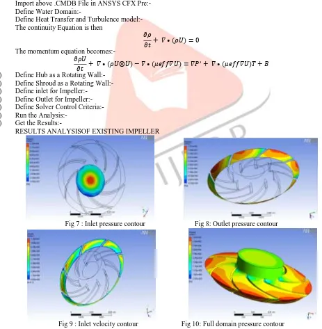
RESULTS ANALYSISOF EXISTING IMPELLER
Fig 7 : Inlet pressure contour Fig 8: Outlet pressure contour
Fig 9 : Inlet velocity contour Fig 10: Full domain pressure contour
IJEDR1602049
International Journal of Engineering Development and Research (www.ijedr.org)279
Head Generated :- 𝑃𝑜𝑢𝑡𝑙𝑒𝑡−𝑃𝑖𝑛𝑙𝑒𝑡 𝜌∗𝑔
:- (1.551×10⁵–1.330×10⁴)/(1000*9.81) :- 14.45m
Table 6- Head Comparison experimental with CFD Results Sr No. Description Head
(Experimental) Head (CFD) Percentage Variation
1 32B Pump 14.05m 14.45m 2.7681%
VI.OPTIMIZATION WITH TAGUCHI METHOD
Table 7:Orthogonal Array L9 of Taguchi Method using Minitab-16 software
Number of Modified impeller Inlet Angle (degree) Outlet Angle (degree) Number of Blades
Modified Impeller-1 38˚ 27˚ 6
Modified Impeller-2 38˚ 29˚ 8
Modified Impeller-3 38˚ 31˚ 10
Modified Impeller-4 40˚ 27˚ 8
Modified Impeller-5 40˚ 29˚ 10
Modified Impeller-6 40˚ 31˚ 6
Modified Impeller-7 42˚ 27˚ 10
Modified Impeller-8 42˚ 29˚ 6
Modified Impeller-9 42˚ 31˚ 8
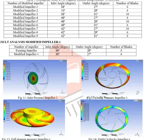
VII.RESULT ANALYSIS MODIFIED IMPELLER-1
Number of impeller Inlet Angle (degree) Outlet Angle (degree) Number of Blades
Existing Impeller 40˚ 29˚ 8
Modified Impeller-1 38˚ 27˚ 6
Fig 11: Inlet Pressure Impeller-1 Fig12: Outlet Pressure Impeller-1
Fig 13: Full domain pressure Impeller-1 Fig 14: Outlet Velocity Impeller-1
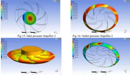
VIII.RESUT AND ANALYSIS MODIFIED IMPELLER-2
Number of impeller Inlet Angle (degree) Outlet Angle (degree) Number of Blades
Existing Impeller 40˚ 29˚ 8
IJEDR1602049
International Journal of Engineering Development and Research (www.ijedr.org)280
Fig 15: Inlet pressure Impeller-2 Fig 16: Outlet pressure Impeller-2
Fig 17: Full pressure domain Impeller-2 Fig 18: Outlet Velocity Impeller-2 Same method we analysis of Modified impeller 3 to 9 and we get the results below table.
IX.OPTIMIZATION TAGUCHI RESULT TABLE
TABLE 8:Optimization Result Table Numbe r of Modifi ed Impelle r Inlet Angle (Degree) Outlet Angle (Degree) No. of Blades Outlet Pressure (Pa) Inlet Pressure (Pa) Head (m) Velocity (m/sec) Torque (N.m) Power Consum ed (Watt) Efficien cy (%) Impelle
r-1 38˚ 27˚ 6 1.60×10
5 1.29×10⁴ 14.94 16.37 10.95 3208.92 81.39 Impelle
r-2 38˚ 29˚ 8 6.83×10
4 -8.04×10⁴ 15.16 20.04 11.91 3490.54 79.83 Impelle
r-3 38˚ 31˚ 10 1.21×10
5 -4.20×10⁴ 16.64 16.37 9.88 2896.72 83.63 Impelle
r-4 40˚ 27˚ 8 9.95×10
4 -5.22×10⁴ 15.46 23.50 11.05 3237.16 82.00 Impelle
r-5 40˚ 29˚ 10 1.61×10
5 -2.52×10³ 16.62 15.26 9.01 2640.94 85.19 Impelle
r-6 40˚ 31˚ 6 6.44×10
4 -7.93×10⁴ 14.65 22.18 10.99 3219.67 80.40 Impelle
r-7 42˚ 27˚ 10 1.31×10
5 -4.98×10⁴ 18.46 15.40 9.06 2655.10 84.61 Impelle
r-8 42˚ 29˚ 6 6.47×10
4 -8.74×10⁴ 15.50 24.35 9.56 2800.78 86.22 Impelle
r-9 42˚ 31˚ 8 7.56×10
4 -6.20×10⁴ 14.02 20.22 11.18 3277.33 80.24
There are different 9 cases of modified impeller analysis. (Shown in above table 6.15) The result of Taguchi optimum head is 18.46m, Power consumed is 2655.10w, and efficiency is 84.61% at 42˚ inlet angle and 27˚ outlet angle,10 no. of blade of pump impeller.
X.CONCLUSION
‒ The 9 number of analysis are done for those sets of parameters. Analysis values of performance are put in the Minitab software 16 and the set of parameter 42⁰ inlet angle, 29⁰ outlet angle and 10 number of blade predicated. The Minitab software predicated head is 18.46m, power consumed is 2655.10w, and efficiency is 84.61%
IJEDR1602049
International Journal of Engineering Development and Research (www.ijedr.org)281
‒ Set of parameter 42⁰ inlet angle, 29⁰ outlet angle with 10 number of blade is successfully used in the pump by changingparameters level.
‒ By this method in the pump impeller is increases the number of blade which gives the maximum head, efficiency and minimum power consumed. Also outlet angle is same, inlet angle is increases so, that maximum head and efficiency.
XI.SCOPE OE THE FUTURE WORK
‒ By this method, we will optimize other parameters which are not used in this CFD analysis. ‒ Same CFD Analysis will be done to achieve total pressure characteristics.
‒ This method will be also used for other pumps.
‒ This CFD analysis and modelling will be done for pump by other analytical softwares. (Like Catiya, Solid edge, Auto-cad, C++ etc.)
‒ This analysis will be done with other parameters like impeller diameter, diffuser, impeller casing interaction etc., ‒ This analysis will be done for samepump by other DOE method or other optimization techniques.
XII.REFERENCE
Papers
[1] Kiran patel and N. Ramakrishnan, “computational fluid dynamics Analysis of pump”
[2] Manivannan, “computational fluid dynamics Analysis of pump impeller” International Journal of Engineering, Science and Technology, Vol2, No.6,2010,pp.200-206
[3] Mandar tabib, Graeme lane, William yang and m Philip schwarz “cfd simulation of a solvent extraction pump mixer unit: evaluating large eddy simulation and rans based models”, Seventh International Conference on CFD in the Minerals and Process Industries,CSIRO, Melbourne, Australia9-11 December 2009
[4] Vasilios a. grapsas, john s. anagnostopoulos and dimitrios e. papantonis, “experimental and numerical study of a radial flow pump impeller with 2d-curved blades” proceedings of the 5th iasme / wseas international conference on fluid mechanics and aerodynamics, athens, greece, august 25-27, 2007
[5] Maitellic. w. s. de p.1; bbezerra, v. m. de f.; cda mata,w. “simulation of flow in a centrifugal pump of esp systems using computational fluid dynamics” brazilian journal of petroleum and gas | v. 4 n. 1 | p. 001-009 | 2010 | issn 1982-0593
[6] Michal varcholaa, peter hlbocanb, b*, “geometry design of a mixed flow pump using experimental results of on internal impeller flow” international scientific and engineering conference “hervicon-2011 procedia engineering 39 ( 2012 ) 168 – 174
[7] j. manikandan, “performance evaluation of mixed flow pump using computational fluid dynamics” european journal of scientific research issn 1450-216x vol.80 no.4 (2012), pp.479-486
[8] Milan sedlar, “numerical investigation of flow in pump with volute” jana sigmunda 79, 78350 lutin, czech republic
Books
[1] V. K. Jain, Vertical turbine, and propeller pumps [2] By G. K. Sahu, Principles of axial pumps