Study of Centrifugal Type Boiler Feed Pump by Varying
Blade Number
1
M .Jaya Ashwini & Battula Naveen kumar
Assistant Professor, Dept. of Mechanical, Siddhartha Institute of Engineering and Technology, Telangana, India
Abstract: In the present study, design and analysis of boiler feed pump having a flow of 2000 m3/hr, head
of 470 m and operating at 130±10o C has been taken
up. The various pump parameters are obtained from design and pump model is developed using modeling software Creo Parametric. To evaluate the results at given operating conditions, CFD analysis is carried out using Ansys CFX module. Blade number has great influence on the pump performance. Therefore, CFD analyses are carried out for the pump with 5, 6 and 7 blades. Based on performance of every pump model, the best feed pump design is selected. A steady state CFD analysis is carried out using the K-ε turbulence model to solve for the Navier-Stroke’s equation.
Index Terms– feed pump, pump design, CFD analysis, pump performance.
I. INTRODUCTION
A centrifugal pump is a rotodynamic pump that makes use of a rotating impeller to increase the pressure of a fluid. Centrifugal pumps are in general used to maneuver beverages by means of a piping approach. The fluid enters the pump impeller along or close to the rotating axis and is accelerated with the aid of the impeller, flowing radially outward into a diffuser or volute chamber (casing), from the place it exits into the downstream piping method. Like most pumps, a centrifugal pumps converts mechanical energy from a motor to energy of a moving fluid; one of the energy goes into kinetic energy of fluid motion, and a few into potential energy, represented through a fluid stress or by means of lifting the fluid in opposition to gravity to a greater degree. The transfer of energy from the mechanical rotation of the impeller to the movement and strain of the fluid is as a rule described in phrases of centrifugal drive, especially in older sources
written before the modern idea of centrifugal force as a fictitious force in a rotating reference body used to be good articulated. The notion of centrifugal drive isn't in reality required to describe the action of the centrifugal pump. In the modern-day centrifugal pump, lots of the energy conversion is due to the outward drive that curved impeller blades impart on the fluid. Continuously, one of the energy also pushes the fluid right into a round motion, and this circular motion might also carry some power and expand the stress at the outlet. The relationship between these mechanisms was described, with the common combined conception of centrifugal drive as often called that time. Pumps are used in a extensive variety of industrial and residential functions. Pumping gear is particularly diverse, various in kind, measurement, and substances of development. There were giant new developments in the subject of pumping gear. They are used as boiler feed pumps, hot good pumps, sewage and sump pumps, irrigation and drainage pumps, paper mills, deep well pumps and hearth pumps. Centrifugal pumps leave an extraordinarily small discipline for reciprocating pumps, a discipline the place capacities are too low and pressures too excessive to permit a good kind for a centrifugal pump. Nonetheless, this field is being step by step lowered extra. Such development within the development and software of centrifugal pumps is as a result of a couple of motives.
o Their excessive adaptability for high pace electric motor and steam driver.
o Minimal of moving elements and,
o Small size and low price for the amount of liquid moved
● Centrifugal pumps are the most popular pump used and are the chief pump type in the class of kinetic pumps.
● Used in various sectors such as: agriculture, power generation plants, municipal, industries, domestic purposes, etc.
● Common uses include: air, water, sewage, petroleum, petrochemical pumping.
● Consist of two major parts: 1. Impeller (a wheel with vanes) 2. Circular pump
Figure .1 Centrifugal Pumps
Applications of Centrifugal Pumps
● Energy & Oil Industries ○ Refineries and Power Plants ● Building Services
○ Pressure boosting, heating installations, fire protection sprinkler systems, drainage, air conditioning
● Industry and Water engineering
○ Boiler feed applications, water supply (municipal, industrial), wastewater management, irrigation, sprinkling, and drainage and flood protection
● The Chemical and Process Industries
○ Paints, chemicals, hydrocarbons, pharmaceuticals, cellulose, petro-chemicals, sugar refining, food and beverage production
II. RELATED WORK
Hu-se ki et al. conducted analysis of regulating characteristics of boiler feed pump. They emphasized on fitting characteristics equation of feed-water pump under different operations, determining characteristics of feedwater pipeline under
sliding-pressure operation, corresponding resistance coefficient, and finally deducing the equation of lift, efficiency and rotating speed when different loads and different sliding-pressures are adapted only by main feed-water pump variable speed adjusting. They took one power plant 600MW supercritical unit for example to compare the energy consumption of different operation modes, and thus puts forward a more suitable operation mode under different loads, providing theoretical basis for the practical application of project.[4]
Babuet. al did condition monitoring and vibration analysis of boiler feed pump. During their investigation they found that for the BOILER FEED pump the vibration readings show that values are more than normal readings. Spectrum analysis was done on readings and found that mass unbalance in vanes. It was corrected based on phase analysis and vibration readings were observed after modification which gives the values within normal range. It eliminates unnecessary opening of equipment with considerable savings in personnel resources. [5] Birajdaret. al studied about the sources and diagnosis methods to control vibration and noise in centrifugal pumps. They studied about the ill effects of vibration and concluded that during the operation of a boiler feed pump, exact diagnosis of vibration and noise sources is very difficult in centrifugal pumps as this may be generated due to system or the equipment itself. Hence they addressed only some of the issues. [6]
geometrical modifications were performed by them for pump casing. [8]
Agratiet. al carried out study on multistage horizontal boiler feed pump from hydraulic and structural point of view. In their investigation, a complete calculation of rotor dynamic behavior in both configurations had been performed using the finite element method. The model of the shaft had been meshed using beam elements, while linearized coefficients had been evaluated in order to simulate stiffness and damping of sleeve bearings, impeller wear rings, balancing drums and inter-stage seals. Un-damped critical speed map, damped mode shapes and Campbell diagrams were presented and discussed.[9]
Abraham et. al carried out an assessment on design parameters and vibration characteristics of boiler feed pump for auxiliary power consumption. They reduced discharge pressure of BFP, thereby found the most efficient method of reduced power consumption, which increased the efficiency of the plant. They replaced the gear box and studied vibration behavior of the pump. In their investigation, experimental and numerical analysis of vibration characteristics was also conducted. [10]
Elemermackay studied about the problems encountered in boiler feed pump operation and classified them into hydraulic and dynamic instabilities. He studied the interaction between hydraulically induced forces and bearing design parameters and their influence on rotor vibration characteristics. Friction induced partial frequency modes were also discussed in his investigation. [11]. From the above literature review it is observed that very little work has been done on the design of oil guard used in oil thrower in boiler feed pump.
III. SYSTEM OVERVIEW
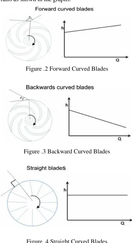
As it has already been stated centrifugal pumps are used mostly for high discharge and low to medium head at the outflow because of this most pumps are designed to maximize the power to discharge ratio. The most common way to do this is through changing the angle of the impeller blades. The angle of the
blades will also have an effect on discharge to head ratio as shown in the graphs.
Figure .2 Forward Curved Blades
Figure .3 Backward Curved Blades
Figure .4 Straight Curved Blades
Blade Angle
IV. DESIGN
In design of centrifugal pump, the parts to be designed are: shaft, impeller, vane, casing, and selection of bearing. To design these parts different methodologies can be obtained through literature survey. From the given conditions, the specific speed is obtained [5]. According to required head, the flow rate and from specific speed, pump of double volute, double suction and single stage type is selected. The minimum shaft diameter can be obtained by using maximum shear stress theory. Impeller and vane are designed according to methodology provided by Church [6]. To design the vane empirical relations are used. API standard [7] is used to design the volute and for bearing selection. There are different methods for volute design, but “throat area from graph of ratio of throat velocity to impeller peripheral speed vs. specific speed” method is used to design a volute. The conversion of KE to PE is very important in pump and that can be achieved with the fine shape of volute. According to selection criterions stated in API standard [7], selection of bearing has been done. Specifications of feed pump are cited in Table I.
Table I. Specifications of Feed Pump Specification Value
Head, H 470 m Flow Rate, Q 2000 m3/hr
Speed, N 4200 rpm Shaft Power 2.87 MW Temperature 120oC to 140oC
Pressure 6 bar Density 1000 kg/m3
The performance characteristics head and efficiency of a pump are influenced by the blade number, which is one of the most important design parameters of pumps [14]. Therefore, changing the blade numbers, CFD analyses are carried out to study the pump performances. The best and suitable blade configuration can be opted after studying the obtained pump performances. The minimum shaft diameter is calculated on basis of strength using maximum shear stress theory. This theory predicts the yielding of ductile material. According to this theory, it is assumed that yield occurs when the shear
stress exceeds the yield strength [8]. The factor of safety is assumed as 4. The hub diameter, DH shown in Figure 5 should be (5/16) to (1/2) times larger than shaft diameter [6]. From minimum shaft diameter, the different dimensions of stepped shaft have been finalized. The stepped shaft is designed on the basis of fitment of standard parts on shaft like; wear rings, throat bush, shaft sleeve, bearings and bearing housings, etc.
Therefore, three different models with 5, 6 and 7 number of blades are developed and those are used for analysis purpose. The grid generation is done using Ansys ICEM CFD software which will allow the user to generate unstructured tetrahedral non-uniform mesh. A finer mesh has generated near blade, hub and shroud region where the geometry has a larger influence on the flow and where large velocity or pressure gradients were assumed to occur.
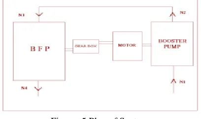
Figure .5 Plan of System
Figure 6 Meshed Impeller
After meshing, CFX-Pre is provided with input data and boundary conditions are applied to solve the problems. At inlet of pump, inlet pressure (14 bar) and at outlet of pump, the required flow (2000 m3/hr)
is provided. Density (1000 kg/m3) as material
property and operating temperature (130o C) is given
to fluid domain. The rotational degree of freedom, 4200 rpm is applied to impeller. Applying these boundary conditions, the problem is solved with 1000 iterations and at the end of iterations solution is converged. The analysis results for pump with 5 blades are shown in Figure 7 and 8.
Figure 7 Velocity Streamline for 5 Blades
Figure 8 Pressure Contour for 5 Blades
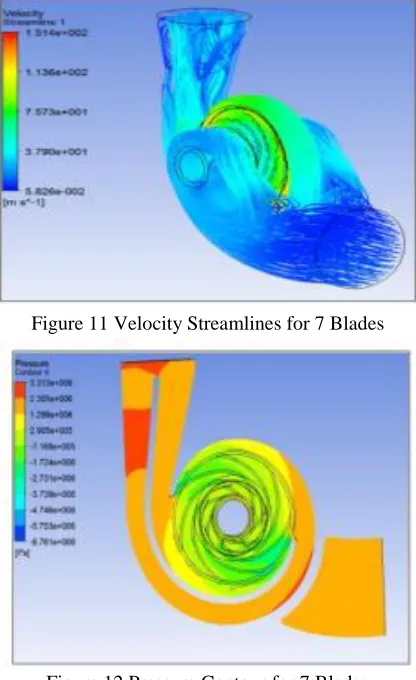
Further, the analyses for a pump with 6 and 7 blades can be carried out. For analysis of a pump with 6 and 7 blades, the geometry is changed to 6 and 7 blades. The analysis procedure is similar as that for 5 numbers of blades. Therefore, following the same steps, the analysis results can be obtained. The input data as well as the boundary conditions are same only. Results for velocity and pressure distribution with 6 and 7 numbers of blades can be seen in Figures 9, 10, 11 and 12 respectively.
Figure 10 Pressure Contour for 6 Blades
Table II Results-Flow vs. Head
Figure 11 Velocity Streamlines for 7 Blades
Figure 12 Pressure Contour for 7 Blades
After performing CFD analysis for feed pumps with 5, 6 and 7 blades, analysis results are obtained. These results are necessary to select the best suited pump
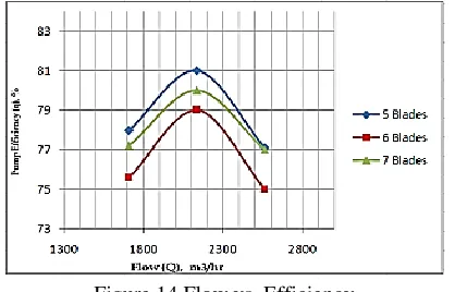
model to fulfill the requirements. Results will show the clear picture of three cases with different impeller blades. From CFD analyses of the pump with 5, 6 and 7 blades, various results are obtained. These analysis results are compared in Table III and Figures 13 and 14.
According to results obtained from the pump analyses with 5, 6 and 7 blades, it can be observed that the streamline flow of a pump with 5 blades is smoother than that with 6 and 7 blades. In case of a pump with 6 and 7 blades, the flow streamlines are mixing at outlet. From the pressure contours for a pump with 5, 6 and 7 blades, it can be observed that the pressure at inlet to impeller is reducing. If the
pressure at inlet will so much low then there may be chances of cavitation in the pump. Therefore, cavitation point of view, the pump with 5 blades is at safer side.
The limitation of space between blade and flow stream gets increased with increase in blade number. The area of low pressure region at the suction of blade inlet grows continuously. With increase of the blade number, total pressure in the region of flow grows continuously. The head of centrifugal pump grows all the time with the increase of blade numbers and total pressure too, but the change in hydraulic efficiency with variation in blade number is complex.
Figure 13 Flow vs. Head
No. of
Blades Head, m
5 475.17
6 476.20
If the blades are too more, the crowding effect phenomenon at the impeller is serious and the velocity of flow increases, also the increases of interface between fluid stream and blade will cause the increment of hydraulic loss [14]. The critical speed is inversely depends upon the shaft deflection. Therefore, if the shaft deflection is more, lower the critical speed. The machine should not fall below the permissible limit of critical speed.
Figure 14 Flow vs. Efficiency
Therefore, critical point of view, the system is on safer side with 5 blades. The pump model with 5 numbers of blades provides the better performance, therefore it can be selected as best performing model and the analysis results are obtained.
V. CONCLUSION
Centrifugal Pumps transfer rotational kinetic energy to increase the hydrodynamic energy and head of fluid flow. When designing a Centrifugal Pump, Blade Angle, Rotations per Minute, and the number of impeller blades all impact the efficiency and discharge of a pump. Some conclusions on the design and CFD analysis of centrifugal type feed pump are,
o The dimensions recommended for all parts of the pump are meeting the design requirements.
o CFD analysis shows that, feed pump with 5 blades has the best performance compared to 6 or 7 blades.
REFERENCES
[1] Christian Allerstorfer, “Bachelor Thesis Centrifugal Pumps”, Alma Mater Leobeinses University, Leoben.
[2] John Anagnostopoulos, “CFD Analysis and Design Effects in a Radial Pump Impeller”, Wseas Transactions on Fluid Mechanics, Volume-1, Issue-7, July-2006, PP. 763-770.
[3] H Sedaghati Nasab, M Massoumian, H Karimi, “CM Experiences with Boiler Feed Pump”, Journal of Worlds Pump, January-2011.
[4] Greg Case, William Marscher, “Centrifugal Pump Mechanical Design, Analysis and Testing”, Proceedings of 18th International Pump User’s Symposium, PP. 119-134.
[5] R P Horwitz, “The Affinity Laws and Specific Speed in Centrifugal Pumps”, 14th Technical Information Bulletin, 2005, PP. 1-5.
[6] Austin H Church, “Centrifugal Pumps and Blowers”, J Willey, John Willey and Son’s Publication, Michigan, 1944.
[7] “Centrifugal Pumps for Petroleum, Petrochemical and Natural Gas Industries”, ANSI/API Standard-610, 7th Edition, API Publishing Services, Washington, September-2010.
[8] C R Mischke, “Design of Shaft”, Shaft and its Design Based on Strength, Module-8, Lesson-1, Version-2, 1989.
[9] Khin Cho Thin, Mya Mya khaing and Khin Maung Aye, “Design and Performance Analysis of Centrifugal Pump”, World academy of Science, Engineering and Technology, 2008, PP. 422-429.
[10] Igor Karassik, J Messina, P cooper, C Heald, “Pump Handbook”, 3rd Edition, McGraw Hill Publication, New York, 2001.
[11] S R Shah, S V Jain, V J Lakhera, “CFD for Centrifugal Pumps: A Review of the State-of-the-Art”, Chemical, Civil and Mechanical Engineering Tracks of 3rd Nirma University International Conference, Ahmedabad, India, 2012, PP. 715-720.
[12] M Mohammed Mohaideen, “Optimization of Backward Curved Aerofoil Radial Fan Impeller using Finite Element Modeling”, 2012, PP. 1592-1598.