P a g e | 1718 Experimental 120cc Mono Cylindrical Design Motor To Analyze Vortex And Multiple
Intake Ignition Sites.
1M. SUDHEER,2Dr.P. RAMESH BABU,3Mr. B. VENKATA NARAYANA
1PG SCHOLAR, DEPEARTMENT OF MECHANICAL ENGINEERING,SRISAI EDUCATIONAL SOCIETY'S GROUP
OF INSTITUTIONS-KODAD
2
PROFESSOR, DEPEARTMENT OF MECHANICAL ENGINEERING, SRISAI EDUCATIONAL SOCIETY'S GROUP
OF INSTITUTIONS-KODAD
3
ASSISTANT PROFESSOR, DEPEARTMENT OF MECHANICAL ENGINEERING, SRISAI EDUCATIONAL
SOCIETY'S GROUP OF INSTITUTIONS-KODAD
ABSTRACT:
The intent of this study is to design, construct and test cylinder with a hot tub and a variety of
ignition sites. Side design uses solid Floworks Works to model airflow inside the head and disc.
The calculation of the vortex rate and the volumetric flow rate of the results. It took many
attempts at designing the site before finalizing an appropriate design. Once arrived at an
appropriate design, it was built using the rapid prototyping printing method known as 3-D
(cast-die-casting). Installation of valve guides and seats on the head. And after valves, springs,
retainers have been measured to allow testing. The entrance has been created using the stereo
print stone because of the closure has a smooth surface and thin walls. A wheel bolt was
constructed to measure the transverse rotation of the gas in the cylinder type. The pilot chairman
of tests at the University of Miami bank flow in the laboratory of internal combustion engines.
The results were compared with experimental work and theoretical modeling. The results closely
match. The difference between experimental and theoretical values of high spiral error rates of
less than 3% error and cycle ratio of less than 10%. Scenario of low snail, and the error was less
than 30%. Measuring the flow velocity of a scenario, the spiral increase of 28.87 CFM and swirl
ratio was measured as 2.87. Creating FlowWorks SolidWorks should be accurate results for a
high-spiral scenario and more different geometry tests.
INTRODUCTION:
The purpose of this project was to design a
cylinder head with variable swirl and
variable ignition sites. The test engine is a
Honda GX120 single cylinder spark ignited
internal combustion engine. It is 120cc and
air cooled. This experiment used the CFD
Solid Works. Floworks was used to optimize
the experimental cylinder for swirl and flow
rate. The Solid Works Flow Simulation
software uses the K-E turbulence model.
The software is capable of analyzing
internal, external, compressible,
incompressible, turbulent, and laminar flow.
The software is also capable of heat transfer
analysis. It was developed by Mentor
Graphics Corporation and can be embedded
in most major 3-D modeling programs. As
defined by Stone in Introduction to Internal
Combustion Engines, swirl is the “ordered
rotation of air about the cylinder axis”. He
mentions that there are two ways to create
swirl. The first method is to use a shrouded
intake valve so that the direction of the air
can be controlled. This is difficult since the
valve cannot rotate and often causes wear
problems at the valve rocker arm contact
point. There is also a large decrease in
volumetric efficiency because of the small
flow area. The second method is to design
the inlet passage to create swirl. There are
two port geometries commonly used helical
and tangential. This is the concentration of
this paper. There are many ways to define
swirl. In this paper we will define swirl as
the ratio between tangential velocity and
vertical velocity of air traveling down the
cylinder. This ratio should be directly
proportional to angle of inclination of the
streamlines. Based on the computer modeled
data, the average tangential velocity will be
found in the cylinder and compared with the
average axial velocity to give the swirl ratio.
In order to verify these results, an
experimental cylinder head was built and
tested on a flow bench. A pin wheel was
used to calculate the tangential velocity. In
addition to comparing swirl, the flow bench
was also used to compare the experimental
and the computer model flow rate data.
There are three common types of swirl
measuring techniques. The pin wheel is
employed in this experiment. To construct a
pin wheel swirl meter, a small piece of flat
material (paddle) is attached to a bearing
and allowed to rotate about the axis of the
cylinder. The pin wheel is considered to
move freely and not impede the flow of
gasses. The rotational velocity of the pin
wheel is used to calculate the velocity of the
rotating gasses. Typically, measurements are
take at 1 to 1.5 bore diameters down the
cylinder. Another similar technique is to
remove the paddle and place a honeycomb
air straightener in its place. This is usually
called an impulse swirl meter (Heywood).
The torque exerted on the air straightener is
used to determine the angular momentum of
the rotating gasses. The third technique
utilizes a laser anemometer to measure
P a g e | 1720
the most costly and requires averaging of
data which can produce errors. The
advantage of swirl is that it increases
burning rate, which decreases knock and
increases homogeneity of mixtures. This is
especially important at low operating
speeds. Swirl and other gas motions create
small scale turbulence during compression
and combustion. This small scale turbulence
is directly related to flame speed (Pozniak,
1985). As stated by Pozniak, “turbulence
intensity should be proportional to the
square root of dissipated swirl energy”.
Squish is an additional method to create
turbulence during the combustion process.
Swirl is generally considered to create more
turbulence than squish. Squish is caused by
creating a narrow area between the piston
and head when at top dead center (TDC) that
pushes gasses into the main combustion
area. Squish causes increased un-burnt
hydrocarbons. The amount of squish area in
this design was determined by the
restrictions imposed by swirl generation.
SIMULATION:
As discussed earlier, the computer modeling
for this thesis used Solid Works Floworks.
Mesh generation was accomplished utilizing
the methods provided by the software. The
remainder of this chapter will discuss
different iterations that eventually
determined the final design of the cylinder
head. The static pressure difference between
the inlet and the outlet used in all iterations
was 28 inches of water(6.97 kPa). These
pressures were considered to be static and
all walls were modeled as real walls in the
solver. The valve lift was .200” (5.08mm).
The original design intent was to use two
intake ports. One intake port would create
swirl while the other would reduce the swirl.
It was decided to begin the design process
with the swirl port. The intake port in the
original cylinder head was round, entering
horizontally smoothly turning downward
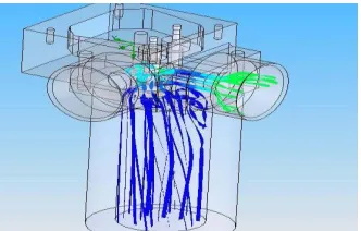
into the cylinder. The initial swirl port
results can be seen in figure 1. A close up of
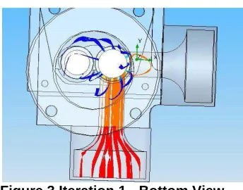
the valve can be seen in figure 2. In figure 3
there is a bottom view of the cylinder. It is
possible to see from this view that there is
virtually no swirl developed. The bottom
view shows the streamlines exiting around
the valve and no noticeable swirl occurs.
The flow rate through the head in the first
iteration is 25.1 CFM and the swirl ratio was
measured at .31.
Figure 2 Iteration 1 - Valve View
Figure 3 Iteration 1 - Bottom View
For the second iteration, a design from a
production engine was copied. As a basis for
this design, the cylinder head from the 4.6L
Ford 4-valve modular V-8 was used. When
one of the intake valves is deactivated
during low RPM operation swirl is
produced. When both intake valves are
activated during high RPM, operation swirl
is dramatically reduced. The use of both
intake valves at high RPM is to increase
volumetric efficiency and therefore, power.
For this study, the original Honda 120cc
engine utilized two valves, not four valves.
This removed the option of deactivating one
intake valve to produce swirl. The use of
two intake valves increases engine cost
substantially. In the Ford engine, the swirl
port is elevated around 35 degree
The previous design did not create sufficient
swirl. The third iteration would be similar,
but the port would be half as tall With this
design there is more rotational flow, but the
rotation is still not about the axis of the
cylinder. The swirl pattern can be seen
closer in figure 8. Even though the port that
would be used to reduce swirl was closed
off, its geometry could interfere with the
generation of swirl. The flow rate for the
third iteration was calculated as 10.5 CFM
and the swirl ratio increased to .88. In the
fourth iteration, the swirl reducing port was
removed so that it would not interfere with
the generation of swirl
Experimental Setup:
Since most of the design work was done in
SolidWorks, this design did not require
many mechanical iterations. The first
prototype was build from SLA (stereo
lithography). The goal of this first prototype
was to verify the fit of the cylinder head. It
also was important in that it allowed for
easier visualization of possible iterations
that are difficult when trying to view a 2D
computer screen. A UV curing laser is used
to harden light sensitive liquid polymer.
This is the basic technology behind SLA. A
P a g e | 1722
harden the surface of the liquid polymer.
The initial surface is close enough to a
platform that is parallel to the liquid surface,
so that the hardened polymer bonds to the
surface and build the initial layer. Then, the
platform is lowered and another layer is
formed by the laser and is bonded to the
previous layer. This is repeated until a series
of layers form a 3D part. Since there is no
support by liquid underneath, cantilevered
pieces of parts support structure is required.
It is built by the model maker in a
post-processing program and is created with the
same resin and at the same time as the
model. The consistency is similar to window
screen and is designed to be broken away
from the model after completion. After
being removed from the SLA machine, the
part is required to be rinsed and then post
cured in a UV oven. Parts can be created in
the matter of hours to days depending on
complexity. Setting up the part to be made
and operating the machine takes significant
skill and attention unlike some other
methods. The accuracy of SLA is one of the
highest of rapid prototyping methods. The
model can only be made out of one type of
material and are limited to photosensitive
polymers. Parts are often brittle and affected
negatively by high humidity. Materials can
be made clear, but are usually opaque. For
added strength, parts can be nickel coated,
making them stronger.
CONCLUSION:
The results of the high swirl scenario were
extremely close. The swirl was measured at
½ a cylinder bore from the head surface.
Other experiments usually measure the swirl
at 1.0 to 1.5 bore diameters below the head
gasket surface, however half the cylinder
bore was chosen for computer model
variation. Since this head used a helical port
swirl developed immediately after exiting
the valve and does not rely on valve
shrouding or combustion chamber design,
swirl developed extremely close to the head
and would only decrease as it moved farther
down the cylinder Despite the inaccuracy of
the low swirl case, the high swirl
experimental flow rate was 28.87 CFM
while the theoretical results were 29.71
CFM. The swirl ratio for the experimental
was 2.87 as compared to 2.59 for the
theoretical. These results are all within 10%
or less, which shows good correlation. Since
these comparisons are for helical ports, we
can conclude that SolidWorks Floworks can
be used to help design helical ports and
combustion chambers. Future work should
investigate the surface roughness of the
swirl reducing orifices in the prototype
cylinder head as this may affect the
rate. Further work will be needed to prove
the accuracy of the software with more
complex designs, such as shrouded valves
and complex combustion chambers.
REFERENCE:
Heywood, John B. Internal
Combustion Engine Fundamentals. NYC, McGraw-Hill: 1988.
Lilly, L.R.C. Diesel Engine
Reference Book. London,
Butterworths: 1984.
Pozniak, D. , Rydzewski, J. “A
Study of In-Cylinder Air Motion in the General Motors Vortec 4.3L, V-6 Engine” Detroit, SAE: 1985.
Pulkrabek, W. Engineering
Fundamentals of the Internal
Combustion Engine. Upper Saddle River, N.J: Prentice Hall, 1997.
Stone, R. Introduction to Internal Combustion Engines. Warrendale,