ISSN 2286-4822 www.euacademic.org
Impact Factor: 3.4546 (UIF) DRJI Value: 5.9 (B+)
Implementation of attendance system based on
UHF RFID technique
HAYDER K. ALJEBORRY
Almustaqbal University College Babylon, Iraq [email protected]
MUSTAFA F. ALBAGHDADI
University of Babylon Babylon, Iraq [email protected]
AHMED F. ALBAGHDADI
Almustaqbal University College Babylon, Iraq [email protected]
Abstract:
As it's known there are many problems of using traditional method to get the attendances persons by using pen and paper. These problems can be represented by cheat. The proposed system develops another method to get attendees by using RFID technology. The proposed system consists of tags reader camera and base station. The system can be demonstrated by five steps.
about any person and any date. Also the administrator can add unlimited number of users or remove any user from the system.
Key words: RFID, UHF tag, UHF Reader, VB.NET, USB cam.
1- INTRODUCTION
Like bar code recognition, RFID relies on tagging in order to identify objects. RFID tags don’t need to be visible to be read unlike bar codes. An RFID reader sends a radio signal, which is picked up by an RFID tag and then transmits back a string of data. Depending on the size and sensitivity of the strength of the transmission, and the reader’s antenna the tag can be several feet away from the reader, enclosed in a book, box, or item of clothing. There are two types of RFID system: passive and active. Passive RFID tags are powered by the current that the reader’s signal induces in their antennas. In an active RFID system, the tag has its own power supply. Active systems can transmit for a much longer range than passive systems, and are less error-prone. They are also much more expensive [1].
2- HISTORY OF RFID
global standard is released in January 2005. Expected that worldwide revenue for RFID technique would eclipse 1.2$ billion in 2008. Imports increased about 31% over the previous year. RFID technology participated in markets such as: access control, sensors and metering applications, payment systems, communication and transportation, parcel and document tracking, distribution logistics, automotive systems, livestock/pet tracking, and hospitals/pharmaceutical applications [19].
3- RFID VS. BAR CODES [21]
Generally, barcode uses laser light as data carrier while RFID uses radio waves to carry information. In the following a detailed of comparison between RFID and bar code technology.
i. Memory Size/Data Storage
Bar codes can only hold a limited amount of data approximately 20 digits while RFID tags are capable of holding far more information. Though RFID tags can be made with smaller memories to hold only a few bytes, the current state of technology puts the upper limit at 128 K bytes, orders of magnitude larger than most bar code symbols. 96 bits memory capacity is used in this proposed system.
ii. Read/Write
Bar codes are not able to modify the identification (ID). In contrast, RFID tags have an addressable, writeable memory that can modify ID number and high number of times over the life of the tag.
iii. Line-of-Sight
propagate through many solid materials. In addition, tags embedded inside objects, and not just applied to packaging, it can also be read without problems. Bar codes require a direct line of sight with the scanner in order to work properly. This means that bar codes must be placed on the outside of packaging and objects must be removed from pallets in order to be read.
iv. Read Range
The read ranges of RFID tags vary widely, depending on frequency of operation, antenna size and whether the tag is active or passive. The reading range of bar codes can be quite long. Bar code scanners can be made to scan tags up to several yards away, though only under certain conditions and not without a direct line of sight. The reading range used in this proposed system is around 9 meters.
v. Multiple read and Anti-collision
RFID systems can read multiple tags simultaneously so pallet of RFID items wouldn't need to be unpacked. Whereas a pallet of bar-coded items would need to be unpacked and scanned individually in order to be inventoried.
vi. Access Security
vii. Difficult to Replicate
Because RFID tags and electronics are so much more complex, then it is difficult to build or replicate it. In other side the bar code is unprotected for being replicated.
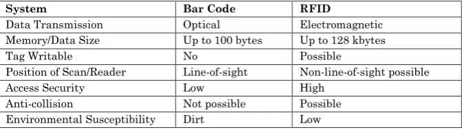
Table 1-1 Comparison of Bar Code vs. RFID System Characteristics
System Bar Code RFID
Data Transmission Optical Electromagnetic Memory/Data Size Up to 100 bytes Up to 128 kbytes
Tag Writable No Possible
Position of Scan/Reader Line-of-sight Non-line-of-sight possible
Access Security Low High
Anti-collision Not possible Possible Environmental Susceptibility Dirt Low
4- RFID SYSTEM COMPONENTS
distance. In passive RFID systems, maximum operating distances for reading and writing operations are not always the same. The reason is that when writing to its memory, most tags require more power and, therefore, the operating distance is reduced. The maximum distance for reading operation is called read range while the corresponding distance for the writing operation is called write range [25]. Figure 1 show passive and active transponders. The second part is Reader. It is responsible for reading the identification number (ID) of each tag in its range .The task of reader is to receive commands from the computer and executes them independently. Figure 2 shows the most important reader components. RFID reader has one antenna or more. The task of antenna is to emit the transmission output in a suitable manner and to record the transponder signal. The antennas have different style depend on the required application (reading range, grouping ability, operation frequency ... etc.). Normally, the antenna and reader are connected with other by 50 Ohm coaxial cable. The RF connection between tag and reader is fully controlled by the reader in the case of passive tags, which means the tag is not capable of sending data unless triggered by the reader. The communication from the reader to the tag is referred to as the forward link, while the communication from the tag to the reader is referred to as the reverse link.
Figure 1 Type of tags (A- Passive tag, B- Active tag) [23].
Pchip
Reader Interface antenna
Transponder chip P1-Pchip
P1
A- Passive tag
Reader Interface
antenna Transponder chip
P1
P1
Figure 2 Reader components
5- PROPOSED SYSTEM
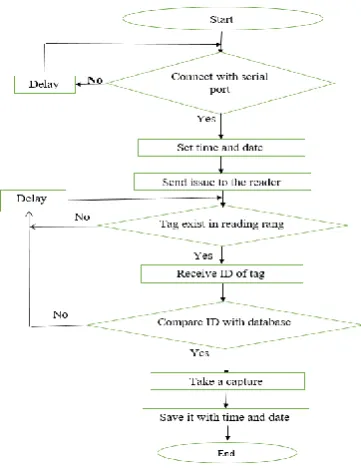
The basic idea of the proposed system is to design an applicable electronic attendance system instead of traditional systems that use papers which increase the accuracy and safe information from fraud. The proposed system consists of Tags, Reader, USB camera and base station. All these part work together according to the following block diagram
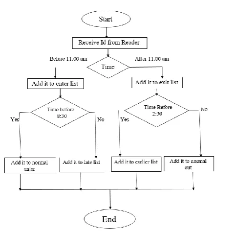
Fig4. Block diagram of base station operation
The above block diagrams demonstrate exactly how the proposed system operates. Also the following image explains the Graphical User Interface (GUI) of each tap of program.
Fig 5. display GUI
Fig6. Edit GUI
The Edit GUI used to add or delete any user by just insert the name of user and the ID of RFID tag and click Add.
Fig7. the main GUI
From the main GUI, The in charge person can start and stop the system, also he can go to any GUI in the system and print the report of any day he want or any person he want.
6- REFERENCES
[2] Silman, J., “Steganography and Steganalysis: An Overview”, SANS Institute, 2001
[3] Wang, H & Wang, S, “Cyber warfare: Steganography vs. Steganalysis”, Communications of the ACM, 47:10, October 2004
[4] Debiprasad Bandyopadhyay, Kousik Dasgupta, J. K. Mandal, Paramartha Dutta, "A Novel Secure Image Steganography Method Based On Chaos Theory In Spatial Domain" International Journal of Security, Privacy and Trust Management (IJSPTM) Vol 3, No 1, February 2014
[5] Chandramouli, R., Kharrazi, M. & Memon, N., “Image steganography and steganalysis: Concepts and Practice”, Proceedings of the 2nd International Workshop on Digital Watermarking, October 2003
[6] Anderson, R.J. & Petitcolas, F.A.P., “On the limits of steganography”, IEEE Journal of selected Areas in Communications, May 1998
[7] Currie, D.L. & Irvine, C.E., “Surmounting the effects of lossy compression on Steganography”, 19th National Information Systems Security Conference, 1996
[8] Johnson, N.F. & Jajodia, S., “Exploring Steganography: Seeing the Unseen”, Computer Journal, February 1998
[9] “Reference guide: Graphics Technical Options and Decisions”
[10] Owens, M., “A discussion of covert channels and steganography”, SANS Institute, 2002
![Figure 1 Type of tags (A- Passive tag, B - Active tag) [23].](https://thumb-us.123doks.com/thumbv2/123dok_us/7767516.1277618/6.439.148.276.436.571/figure-type-tags-passive-tag-b-active-tag.webp)