ISSN 2348 – 7968
Three Dimensional Computational Studies on Aileron Morphing And
Variable Wing Sweep Morphing
Vadivelu PP
1
P
, Shanmugam PP
2
P
and Parammasivam K.MP
3
P
1
P
Department of Aeronautical Engineering, Bannari amman Institute of Technology, Erode, India
P
2
P
Department of Aerospace Engineering, Madras Institute of Technology, Chennai, India
P
3
P
Department of Aerospace Engineering, Madras Institute of Technology, Chennai, India
Abstract
Morphing wings are the subject of intensive research interest today due to their potential to improve aircraft versatility for multiple mission requirements. This report focuses on the development of aileron morphing and variable wing sweep morphing on a selected RC model to improve the range and maneuverability of an endurance unmanned aerial vehicle. In general, the aerodynamic performance can be improved by using aileron morphed wing instead of a separated aileron which avoids geometrical discontinuity. Initially, two dimensional and three dimensional computational studies are carried out on morphed aileron wing and un-morphed aileron wing for maximum and minimum aileron deflection angles. In which, Morphed aileron wing has given better aerodynamic performance results that shows improved range. On the other hand, three dimensional analysis carried out for two sweep configurations (take off and cruise sweep configurations) to compare the effectiveness of the wing. From the computational results, good sweep configurations are recommended to get efficient mission objectives during flight.
Keywords: Aerodynamic performance, Aileron
morphing, Variable wing sweep morphing.
1. Introduction
Morph can be defined as “to cause something to change its outward appearance”. Each aircraft today has a wing that matches the purpose for its use. The inspiration for the concept of morphing wings comes from birds. As contradictory as it may seem, nature is much more far ahead in the effectiveness of flight that any other man made aircraft found today. Birds are able to adapt their wings to the conditions that need to be met at the time. Many of the research in the aircraft industry are looking for the development of an aircraft wing that is able to mimic this kind of ability.
An airplane with this kind of technology would be able to perform different roles that may seem paradoxical at first. A commercial plane with this technology could be able to adapt its wings for high lift during takeoff, extend them
fully for optimum cruising, fold them lightly for efficient descent and change them back to high lift for landing. The advantages for this kind of technology are quite impressive and would allow aircraft to get the most efficiency during flight as well as its adaptability to harsh environments.
1.1 Aircraft Determination
Once the baseline aircraft requirements and category is chosen, hobby websites are searched for aircraft that would meet the project requirements. The list is then narrowed down to Calmato-40 Nitro Airplane.
2. Aileron Morphing
The lift-to-drag ratio also has a significant effect on a UAV flight range as given in the Breguet equation for constant velocity and lift coefficient
(1) Since CRLR/CRDR is directionally proportional to the range, an increase in the CRLR/CRDR will cause the range of the UAV to also increase. It has been acknowledged that morphing wing technology has the potential of increasing the aerodynamic efficiency (L/D ratio).If we use conventional aileron, there will be a geometrical discontinuity. This geometrical discontinuity causes profile drag. If it is avoided, we can get better aerodynamic performance. This is achieved by implementing aileron morphing.
2.1 Two dimensional analysis
The aerodynamic coefficients analysis are carried out by fixing the aileron deflection angle as a constant for different wing angles of attack at constant Mach number=0.1. From the analysis, observed that Maximum average increment in CRlR/CRdR using morphed aileron wing=1.49674. Due to increase in CRlR/CRd Rratio, the range of morphed aileron wing UAV flight also increases. So, there will be reduction of fuel consumption in the morphed aileron wing UAV.
2.2 Three dimensional analysis
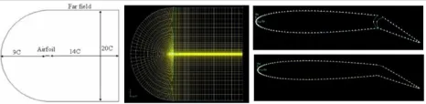
Main aim of this CFD study is to analyze the flow around the un-morphed aileron wing and morphed aileron wing, the basic approach towards it is to perform a 3-D CFD analysis on a half-symmetric model of the wing at two distinct aileron deflection configurations - minimum and maximum aileron deflection angle. The complete geometry is for this study is defined & modelled in CATIA. The mesh was generated using GAMBIT 2.4 and FLUENT 6.3 was the solver employed in this CFD study.
2.2.1 Post processing
The most crucial phase of a CFD analysis is the post processing phase which represents the art of presenting results in an intelligible and meaningful manner. The FLUENT Getting Started Guide defines post processing as the act of analyzing the numerical results of a CFD simulation using reports, integrals and graphical analysis tools such as contour plots, animations etc. In this paper, results have been primarily displayed using contour plots.
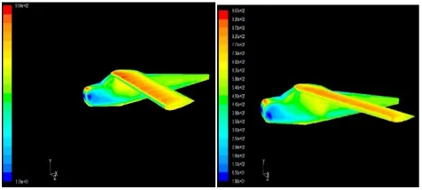
Static pressure contours: Static pressure is defined as that pressure which is experienced by an object in flow only due to the random motion of the gas molecules hitting the surface of the body. The static pressure of a flow decreases with velocity and altitude as well. Figure 2 and 3 shows a combination of the static pressure contours over the wall i.e. wing surface for each case.
Fig 2: Static pressure contours of Un-morphed aileron wing (Left) and morphed aileron wing (Right) for δ=0P
0
Fig. 3: Static pressure contours of Un-morphed aileron wing (Left) and morphed aileron wing (Right) for δ=25P
0
From the static pressure contours, the flow stagnation at the leading edge is fairly obvious. In conventional aileron wing, static pressure at aileron clearance is more than morphed aileron. Maximum and minimum value of static pressure over the wing also decreases when using aileron morphing.
Dynamic pressure contours: Dynamic pressure is the pressure of the flow associated with the velocity of the flow or by virtue of velocity. Hence, by definition, the dynamic pressure will be high in the flow field where velocity is high and vice versa. Figure 4 & 5 shows a combination of the dynamic pressure contours over the wall i.e. wing surface for each case.
Fig. 4: Dynamic pressure contours of Un-morphed aileron wing (Left) and morphed aileron wing (Right) for δ=0P
0
Fig. 5: Dynamic pressure contours of Un-morphed aileron wing (Left) and morphed aileron wing (Right) for δ=25P
0
The dynamic pressure contours again exhibit the flow stagnation at the leading edge, an insignificant issue. In conventional aileron with δ=25P
0
P
The value of maximum and minimum dynamic pressure over the wing increases when using aileron morphing in both aileron deflection δ=0 and 25. This result fairly validates the increase in lift corroborating the increase in lift coefficient when using aileron morphing.
Total Pressure Contours: Total pressure is the sum of static and dynamic pressure at any point in the flow. Total pressure can also roughly describe the total pressure energy of the flow which can be used to ascertain pressure losses if any in the flow field due to various possible reasons. Figure 6 & 7 shows a combination of the total pressure contours over the wall i.e. wing surface for each case.
Fig. 6: Total pressure contours of Un-morphed aileron wing (Left) and morphed aileron wing (Right) for δ=0P
0
Fig. 7: Total pressure contours of Un-morphed aileron wing (Left) and morphed aileron wing (Right) for δ=25P
0
The total pressure contours indicates an almost uniform total pressure over the whole wing surface except at the trailing edges of the wing. In conventional wing with δ=25P
0
P
, we can see lower dynamic pressure distribution due to flow separation. This might be due to viscous losses or possibly due to flow separation near the trailing edges. Also visible is a small region of low total pressure on the wing tip which is perhaps an indicator of a wing tip vortex. Total pressure decrease near the trailing edges is almost same in magnitude/color from both the cases inducing no such major conclusion for δ=25P
0
P
.
Velocity contours of plane at X=500mm: The flow field in the plane (at X=500mm) is a vivid description of the flow around the aileron as it describes the velocity field around the wing in the plane parallel to the flow direction.
Hence, the plane flow field provides an apt visualization for the overall flow around the aileron. Figure 8 & 9 shows a combination of velocity contours over the plane for each case.
Fig. 8: Velocity contours of Un-morphed aileron wing (Left) and morphed aileron wing (Right) for δ=0P
0
Fig. 9: Velocity contours of Un-morphed aileron wing (Left) and morphed aileron wing (Right) for δ=25P
0
The velocity contours at x=500mm plane from figure 8 shows slight increase in velocity when using aileron morphing. From figure 9, aileron morphing gives nearly 6 m/s increment in maximum velocity value. We can see clear visualization of conventional aileron flow separation due to geometrical discontinuity in the profile. Avoiding this discontinuity will lead to get efficient aerodynamic performance with reduced drag.
3. Variable sweep morphing
Variable sweep changes the wing aspect ratio and area, affecting the aerodynamic forces; the lift curve slope tends to decrease as sweep increases, due to the change in aspect ratio. Changing wing sweep also moves the center of gravity, as well as the aerodynamic center, thus affecting the longitudinal stability of the airplane. The sweep angle also influences the lateral stability, and sweeping the wing back has a stabilizing effect similar to adding dihedral. Variable-wing sweep will be employed on selected UAV, even though compressibility effects at low speeds and low Reynolds numbers are negligible. Here, Variable-wing sweep is used to reduce the fuel consumption.
3.1 Effects of Variable Sweep (Low Subsonic Speed)
1. Efficient subsonic cruise and loiter, 2. Cruise Efficiency,
3. Take-off and Landing Performance, and 4. Excessive Longitudinal Stability.
3.2 Computational 3D analysis
Static pressure contours:
Fig. 10: Static pressure contours of minimum (left) and cruise (right) sweep configuration
From the static pressure contours from figure 10, the flow stagnation at the leading edge is fairly obvious. As stated, the static pressure decreases with increased velocity, this is evident over the wing where a low static pressure region formed over the surface which is lower in case of the higher sweep back possibly indicating minor lift generation as compared to the minimum sweep configuration. This result fairly validates the reduction in lift corroborating the reduction in lift coefficient.
Dynamic pressure contours:
Fig. 11: Dynamic pressure contours of minimum (left) and cruise (right) sweep configuration
The dynamic pressure contours in figure 11 again exhibit the flow stagnation at the leading edge. As mentioned earlier, dynamic pressure increases with velocity. But, it can be observed that the incident region is smaller in case of the cruise sweep configuration i.e. at increased sweep angles – lift produced is less. This reiterates the significant finding of reduced lift generation at higher sweep back angles for the same speed and angle of attack.
Total pressure contours:
Fig. 12: Total pressure contours of minimum (left) and cruise (right) sweep configuration
The total pressure contours from figure 12 indicates an almost uniform total pressure over the whole model surface except at the trailing edges of the wing. This might be due to viscous losses or possibly due to flow separation near the trailing edges. Also visible is a small region of low total pressure on the wing tip which is perhaps an indicator of a wing tip vortex. Total pressure decrease near the trailing edges is almost same in magnitude/color from both the cases inducing no such major conclusion.
Wall shear stress contours: Wall shear stress represented by tau is defined by the normal velocity gradient at the wall in accordance with Newton’s law of viscosity. In FLUENT, for the Spalart-Allmaras viscous model, wall shear stress is calculated using standard wall. Figure 13 shows a combination of wall shear stress contours over the surface for each case.
Fig. 13: Wall shear stress contours for minimum (left) and cruise (right)
sweep configuration
4. Discussions
4.1 Aileron morphing
From two dimensional analysis, Aileron morphing gives increased Cl/Cd ratio than conventional aileron which verifies increment in range of UAV and reduction in fuel consumption. In three dimensional analysis, static pressure, dynamic pressure, total pressure and velocity distribution around Morphed and Un-morphed aileron are taken as contours. Contours shows variation between both aileron wings due to geometrical discontinuity. In which we can visualize the pressure distribution and velocity distribution around the aileron for maximum and minimum aileron deflection angles. From this studies of morphed aileron and Un-morphed aileron, it clearly shows that aileron morphing will act as additional lift producing device by avoiding aero foil profile discontinuity.
4.2 Variable sweep morphing
From the above test data, it is very clear that with increase in sweep angle,
o There is a decrease in the lift generated and so is the case with the lift coefficient.
o Decrease in drag produced as well which is also apparently the same trend shown by the drag coefficient.
The following recommendations can be made from the pursued CFD analysis of a selected UAV model at two different sweep configurations (minimum and cruise):
For phases of flight that require high lift viz. take-off and climb – the minimum sweep configuration is recommended for maximum lift generation.
For phases of flight that require lesser lift in comparison like cruise or loiter – a higher sweep angle configuration is recommended.
In all cases, for experiencing less shear stress on the leading edge – greater sweepback is recommended always.
In all cases of flight, any velocity or angle of attack, greater sweep back will provide less drag and hence is recommended for reducing drag.
Hence, it is hereby recommended that this study be further pursued with greater quality resources to validate the results.
4. Conclusions
The aerodynamic coefficients of morphed aileron wing and un-morphed aileron wing are investigated by using
standard software packages. Obtained CRlR/CRdR values for Un-morphed aileron wing and Morphed aileron wing are plotted with respect to α (in degrees). When comparing the CRlR/CRd Rvalue, got 1.496 as maximum average increment in CRlR/CRdR using morphed aileron wing. Thus the morphed aileron wing gives better aerodynamic coefficients than the un-morphed aileron wing. Increment in CRlR/CRdR results increase in range of UAV flight and reduction in fuel consumption. Three dimensional Computational Fluid Dynamics studies are carried out to visualise the effect of aileron clearance over the wing for maximum and minimum aileron deflection angle. If the wing shape changes more smoothly then, the flow separation will be suppressed and the aerodynamic characteristics will be improved. In addition, three dimensional Computational Fluid Dynamics studies of variable sweep morphing are also carried out to investigate and summaries the effect of changing sweep angle at Mach number 0.1. From the studies, some recommendations are advised to get efficient mission objectives during flight. Thus the effects of Aileron morphing and Variable sweep morphing at Mach number 0.1 are studied through CFD.
Nomenclature
UAV - Unmanned Aerial Vehicle
L/D - Lift-to-Drag Ratio
CFD - Computational Fluid Dynamics
CRlR - Lift coefficient
CRdR - Drag coefficient
δ - Aileron deflection angle
M - Mach number
V - Velocity
References
[1] McCroskey W. J., “A Critical Assessment of Wind Tunnel Results for the NACA0012 Airfoil,” NASA Technical Memorandum 10001 9, USAAVSCOM Technical Report 87-A-5, 1987.
[2] Campanile, L. F., Carli V. and Sachau D., “Adaptive
Wing Model for Wind Channel Tests,” Active Control Technology for Enhanced Performance Operation Capabilities of Military Aircraft, Land Vehicles and Sea Vehicles, Braunschweig, Germany, May 2000.
[3] Monner H. P., Hanselkaa H. and Breitbacha E.,
“Development and Design of Flexible Fowler Flaps for an Adaptive Wing,” Smart Structures and Materials 1998: Industrial and Commercial Applications of Smart Structures Technologies, Proceedings of SPIE, Vol. 3326, pp. 60–70, 1998.
[4] Saggere L. and Kota S., “Static Shape Control of Smart
Structures using Compliant
[5] Mechanisms,” AIAA Journal, Vol. 37, pp. 572–8, 1999.
[6] Lim S. M., Lee S., Park H. C., Yoon K. J. and Goo N.S.,
using a Lightweight Piezo-Composite Actuator (LIPCA),” Smart Material and Structure, Vol.14, pp. 496–503, 2005.
[7] Vos R., Barrett R., de Breuker R and Tiso P.,
“Post-buckled Precompressed Elements: A New Class of Control Actuators for Morphing wing UAVs,” Smart Material and Structure, Vol. 16, pp. 919–26., 2007.
[8] Kudva J. N., “Overview of DARPA Smart Wing
Project,” Journal of Intelligent Material Systems and Structures, Vol. 15, pp. 261-267, 2004.
[9] Hutapea P., Kim J., Guion A., Hanna C. and Heulitt N.,
“Development of a Smart Wing,” Aircraft Engineering and Aerospace Technology: An International Journal, Vol.80, No. 4, pp. 439–444, 2008.
[10] Anderson, John David. Computational Fluid
Dynamics:The Basics With Application, McGraw-Hill, Singapore, 1995.
[11] Raymer, Daniel P., Aircraft Design: A Conceptual Approach , 4 th ed., American Institute of Aeronautics & Astronautics, Reston, 2006.
[12] Whitford, Ray, Design for Air Combat , 1 st ed., Jane’s Publishing, London, 1987.
[13] Abbott, Ira H., Albert E. von Doenhoff and Loius S. Stivers, Summary of Airfoil Data , NACA report TN-824, 1945
[14] Anderson J.D Jr., Aircraft Performance and Design , WCB McGraw Hill, Boston, 1999.
[15] Corke, Thomas C., Design of Aircraft , Pearson Education, New Delhi, 2003
[16] Loftin, Laurence K. Jr., Theoretical and Experimental Data for a number of NACA 6A- Series Airfoil sections , NACA Report No. 903/TN-1368, July 1947.
[17] Harper, Charles W. and Ralph L. Maki, A Review of the Stall Characteristics of Swept Wings ,NASA Report TN D-2373, July 1964
[18] Anderson J.D Jr., Fundamentals of Aerodynamics , Tata McGraw Hill, New Delhi, 2010.