Available online:
http://edupediapublications.org/journals/index.php/IJR/
P a g e | 5219Comparison of SGIG & DFIG with STATCOM
control for AC loads
Kemidi. Navya M-tech Student Scholar
Department of Electrical & Electronics Engineering, Scient Engineering College, Ibrahimpatnam;
RangaReddy (Dt); Telangana, India. Email:[email protected]
K.Sreepal Reddy Assistant Professor
Department of Electrical & Electronics Engineering, Scient Engineering College, Ibrahimpatnam;
RangaReddy (Dt); Telangana, India. Email:[email protected]
ABSTRACT-This project presents an analysis of the three-phase self excited induction generator (SEIG) with static compensator {STATCOM) as a voltage regulator. Current controlled voltage source inverter (CC-VSI) is used as STATCOM, which provides fast dynamic response to maintain constant voltage at SEIG terminals during severe load perturbations and acts as a source and sink of reactive power. The performance equations are derived using d-q variable in stationary reference frame to develop a mathematical model of SEIG-STATCOM system feeding unbalanced loads. Transient analysis of the SEIG STATCOM system is carried out for voltage build-up; switching in STATCOM, application and removal of balanced/unbalanced resistive/reactive loads. The STATCOM regulates the SEIG terminal voltage through reactive power compensation and also suppresses the harmonics injected by consumer loads. A single-phase synchronous D-Q frame theory-based control algorithm is used to generate gating pulses to the three-phase STATCOM. The proposed concept can be implemented with DFIG. By using MATLAB/SIMULINK software.
Keywords—self excited induction generator
(SEIG); single-phase synchronous D-Q frame
theory; static synchronous compensator
(STATCOM)
I INTRODUCTION
In remote areas, plenty of non-conventional energy sources are available. These non-conventional energy sources are used as prime input for the generating systems. Externally driven induction machine operates as a self-excited induction generator (SEIG) with its excitation requirements being met by a capacitor bank connected across its terminals. The SEIG has advantages like simplicity, maintenance free, absence of DC, brushless etc. as compare to the conventional synchronous generator.
Self-excitation phenomenon in induction machines although known for more than a half century. This induction generator is self excited by a suitable capacitor banks across the terminals. This phenomenon is known as capacitor self excitation and the induction generator is called a “SEIG” [2]. A major disadvantage of SEIG is its poor voltage regulation requires a variable capacitance bank to maintain constant terminal voltage under varying loads.
Attempts have been made to maintain constant terminal voltage by using passive elements [5], short –shunt [6] and long -shunt method for a three-phase SEIG [7]. Fixed capacitor and thyristor-controlled inductor known as static Var compensator (SVC) [10] for voltage compensation. By the invention of solid-state self-commutating devices, it is possible to make a static, noiseless voltage regulator, which can provide continuously variable reactive power to the SEIG with varying load to keep terminal voltage constant. This system called STATCOM has specific benefits compared to SVC [12], Schauder and Mehta [13] have derived governing equations of STATCOM to determine the response of the STATCOM.
In this paper, the single phase linear and non-linear load share connected to the three-phase SEIG which cause unbalance current and draws non-sinusoidal current due to non-linearity of load which injects harmonics into the system. The STATCOM is introduced to eliminate the harmonics, provides load balancing and supplies the reactive power and feeding single-phase loads using a three-phase SEIG without de-rating the machine. The transient analysis of the SEIGSTATCOM system under balanced/ unbalanced single-phase linear and non-linear loads and simulated results show that the SEIG-STATCOM system behaves an ideal supply under these unbalanced loads.
II SELF EXCITED INDUCTION GENERATOR (SEIG)
A) Induction generator:
The induction generators offer advantages over synchronous machines, resulting in a simplified installation with economy in first cost and in operating and maintenance expenses. The attractive feature of the induction generator is simplicity of operation.
B) Process of self excitation:
Available online:
http://edupediapublications.org/journals/index.php/IJR/
P a g e | 5220This means that real power flows out of the machine but the machine needs the reactive power. To build up voltage across the generator terminals, excitations must be provided by two modes (i.e., grid connected and isolated mode). In case of a grid-connected mode, the induction generator can draw reactive power either from the grid but it will place a burden on the grid for an isolated mode, there must be a suitable capacitor bank connected across the generator terminals. This phenomenon is known as capacitor self-excitation and the induction generator is called a “SEIG.”
Fig 1.self excitation of induction generator
III STATIC SYNCHRONOUS COMPENSATOR (STATCOM)
The static synchronous compensator is a shunt-connected reactive power compensation device which provides voltage support by generating or absorbing reactive power at the point of common coupling without the need of large external reactors or capacitor banks.
a) Modeling of control scheme of STATCOM:
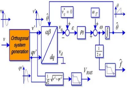
The single-phase synchronous D-Q frame theory-based control algorithm for the three-phase STATCOM is shown in figure 3.2. A single-phase synchronous D-Q frame theory-based control has been used to generate switching pulses to the three-phase STATCOM. In case of a three-three-phase system, initially, the three-phase voltages or currents (in abc frame) are transformed to a stationary frame (α - β) and then to synchronously rotating D-Q frame. Therefore, to transform a signal into a stationary α - β frame, at least two phases are needed. The original signal represents the component of α-axis and 90ƕ lag signal is the β-axis component of stationary reference frame.
Fig 2.Block diagram of D-Q frame theory
The PCC voltages (va, vb, vc), source
currents (isa, isb, isc), load current (il), and dc bus
voltage (Vdc) are sensed and used as feedback signals.
Considering PCC voltages as balanced and sinusoidal, the amplitude of the PCC voltage or system voltage is estimated as
(1)
The transformation of voltages and currents of one particular phase into a stationary α - β frame, then the PCC voltages and load current in stationary α - β frame are represented as
(2)
(3)
(4) Now consider a synchronously rotating D-Q frame for phase “a” which is rotating in the same direction as va (t), Therefore, the D-axis and Q-axis
components of the load current in phase “a” are estimated as
(5) Where cos θa and sin θa are estimated using vaα and
vaβ as follows:
Available online:
http://edupediapublications.org/journals/index.php/IJR/
P a g e | 5221where θ can be estimated using a single-phase PLL structure based on second order generalized integrator. Using the PLL structure the phase angle, amplitude and frequency of the utility are detected. The figure 3 shows the general structure of PLL.
Fig 3 General structure of PLL
IlaD represents the active power component
of the load current as the signals belong to the same axis are multiplied and added to estimate the D-axis component, whereas IlaQ represents the reactive
power component of the load current as the orthogonal signals are multiplied and added to derive the Q axis component. Similarly, the D-axis and Q-axis components of the load current in phase “c” are estimated as
(7) The negative sign of currents in (7) indicates that the load current in phase “c” is equal to phase “a” but 1800 out of phase. As the single-phase load is connected across the phases “a” and “c,” D-axis and Q-axis components for phase “b” are not estimated. The D-axis components of the load current is given as
(8) Similarly, an equivalent Q-axis current component of total load on the system is estimated as
(9) The equivalent D-axis and Q-axis current components of total load are decomposed into two parts namely fundamental and oscillatory parts as
(10)
(11)
The reason for the existence of the oscillatory part is due to the nonlinear and single-phase nature of connected loads in the system. Even if the connected loads are linear in nature, the D and Q components estimated in (8) and (9) would still contain oscillatory parts due to the unbalance caused by single-phase loads. To ensure the power quality, the reference D-axis and Q-axis components of source currents must be free from these oscillatory components. by using low-pass filter the fundamental components are extracted.
To maintain the dc-bus capacitor voltage of the STATCOM at a reference value, it is sensed and compared with the reference value and then they obtained voltage error is processed through a PI controller. The dc-bus voltage error of the
STATCOM Vdcer at kth sampling instant is expressed
as
(12) Where Vdcref (k) and Vdc (k) are the reference
and sensed dc bus voltages of the STATCOM at kth sampling instant, respectively. In the present investigation, the dc-bus voltage reference is set to 400 V.
The output of the PI controller for maintaining a constant dc bus voltage of the STATCOM at kth sampling instant is expressed as
(13) Where Iloss is the active power component of
the current (or D axis current component) that must
be supplied to meet the losses in the STATCOM. Kpd
and Kid are the proportional and integral gain
constants of the dc-bus voltage PI controller, respectively. The source should supply the power loss component of the current (Iloss) along with the
filtered equivalent D-axis current component of the single-phase load estimated in (3.11). In order to ensure balanced and sinusoidal source currents, the
D-axis component of source currents after
compensation must be equal for all the phases and it should not contain any ripple. Therefore, IlD is added
to Iloss and distributed among all the phases equally to
obtain the D-axis component of the reference source current in each phase which can be expressed as
(3.14) I*sDph also indicates the active power
Available online:
http://edupediapublications.org/journals/index.php/IJR/
P a g e | 5222the load and SEIG. The amount of the reactive power component of the current to be injected by the STATCOM is estimated by an ac voltage PI controller. The amplitude of the PCC voltage computed in (3.1) is compared with the reference voltage. The PCC voltage error Ver (k) at kth
sampling instant is given as
(15)
Where Vtref is the amplitude of the reference
PCC voltage and Vt (k) is the amplitude of sensed
three-phase ac voltages at the PCC terminals, at kth instant. The reference voltage is selected to maintain the PCC line voltage at 220 V. The output of the PI controller for maintaining the PCC voltage at the reference value in kth sampling instant is expressed as
(16)
Where Kpa and Kia are the proportional and
integral gain constants of the PI controller, Ver (k)
and Ver (k-1) are the voltage errors at kth and (k-1)th
instants, respectively. IQ (k) is the equivalent Q-axis
component (or reactive power component) of the current to be supplied by the STATCOM to meet the reactive power requirements of both the load and SEIG, thereby it maintains the PCC voltage at the reference value. The per phase Q-axis component of the reference source current required to regulate the system voltage is defined as
(17) I*sQph indicates the magnitude of the reactive
power component of the current that should be supplied to each phase of the source (i.e., SEIG) to achieve the reference terminal voltage. The value of I*sQph can be either positive or negative based on
loading conditions. Using the D-axis and Q axis components of currents derived in (3.15) and (3.18), the phase “a,” α-axis and β-axis components of the reference source current can be estimated as
(18) In the above matrix, the α-axis current represents the reference source current of actual phase “a,” and the β-axis current represents the current that is at π/2 phase lag which belongs to the fictitious phase. Therefore, one can have
(19)
Similarly, reference source currents for phases “b” and “c” are estimated as
(20)
(21) Three-phase reference source currents (i*sa,
i*sb, and i*sc) are compared with the sensed source
currents (isa, isb, and isc) and the current errors are
computed as
(22a)
(22b)
(22c) These current error signals are fed to the
current-controlled PWM pulse generator for
switching the IGBTs of the STATCOM. Thus, the generated PWM pulses are applied to the STATCOM to achieve sinusoidal and balanced source currents along with desired voltage regulation
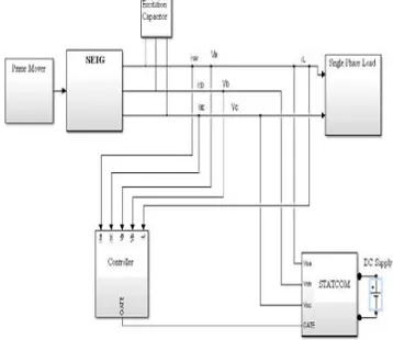
IV SYSTEM CONFIGURATION AND PRINCIPLE OF OPERATION
The schematic block diagram of SEIG with excitation capacitor, STATCOM, load and voltage reference based control scheme is shown in Figure 3.4. The system consists of an SEIG driven by renewable energy-based prime mover. The single-phase consumer loads are connected across “a” and “c” phases of the SEIG. The STATCOM is connected at point of common coupling (PCC). The D-Q frame control algorithm can be modulated for generating switching pulses to the STATCOM. The out-coming signals from the SEIG are the three-phase AC voltages.
Fig 4 block diagram of SEIG-STATCOM model
Available online:
http://edupediapublications.org/journals/index.php/IJR/
P a g e | 5223STATCOM acts as a source of lagging or leading current to maintain the constant terminal voltage with variation in load. Moreover, the STATCOM suppresses harmonics injected by nonlinear loads and provides load balancing while feeding single-phase loads. The STATCOM consists of a two- level, three-phase IGBT based current controlled voltage source inverter and DC bus capacitor.
For simulation a 3.7-kW, 230-V, 50-Hz, Y-connected induction generator has been used to investigate the performance while feeding single-phase loads. A ∆-connected 4-kVAR capacitor bank is connected across the induction generator terminals to provide self-excitation and a induction motor having 3.7-kW, 415-V, 50-Hz, Y-connected is used to drive the SEIG. A three-phase two-level IGBT based VSI has been used as the STATCOM. The STATCOM is connected across the PCC through filter inductors. Both linear and nonlinear loads are considered for testing the system. A single-phase uncontrolled diode bridge rectifier feeding a series R-L load is used as a nonlinear load.
V WIND ENERGY BASICS
Basic information on wind energy and wind power technology, resources, and issues of concern.
Wind Energy and Wind Power: Wind is a form
of solar energy. Winds are caused by the uneven heating of the atmosphere by the sun, the irregularities of the earth's surface, and rotation of the earth. Wind flow patterns are modified by the earth's terrain, bodies of water, and vegetative cover. This wind flow, or motion energy, when "harvested" by
modern wind turbines, can be used to
generate electricity.
How Wind Power Is Generated: The terms "wind energy" or "wind power" describe the process by which the wind is used to generate mechanical power or electricity. Wind turbines convert the kinetic energy in the wind into mechanical power. This mechanical power can be used for specific tasks (such as grinding grain or pumping water) or a generator can convert this mechanical power into electricity to power homes, businesses, schools, and the like.
Wind Turbines: Wind turbines, like aircraft
propeller blades, turn in the moving air and power an electric generator that supplies an electric current. Simply stated, a wind turbine is the opposite of a fan. Instead of using electricity to make wind, like a fan, wind turbines use wind to make electricity. The wind turns the blades, which spin a shaft, which connects to a generator and makes electricity.
Wind Turbine Types: Modern wind turbines fall
into two basic groups; the horizontal-axis variety, like the traditional farm windmills used for pumping water, and the vertical-axis design, like the
eggbeater-style Dairies model, named after its French inventor. Most large modern wind turbines are horizontal-axis turbines.
Turbine Components Horizontal turbine components include:
blade or rotor, which converts the energy in the wind to rotational shaft energy;
a drive train, usually including a gearbox and a generator;
a tower that supports the rotor and drive train; and
Other equipment, including controls,
electrical cables, ground support equipment, and interconnection equipment.
Wind turbine diagram
Turbine Configurations: Wind turbines are often
grouped together into a single wind power plant, also known as a wind farm, and generate bulk electrical power. Electricity from these turbines is fed into a utility grid and distributed to customers, just as with conventional power plants.
Wind Turbine Size and Power Ratings: Wind
turbines are available in a variety of sizes, and therefore power ratings. The largest machine has blades that span more than the length of a football field, stands 20 building stories high, and produces enough electricity to power 1,400 homes. A small home-sized wind machine has rotors between 8 and 25 feet in diameter and stands upwards of 30 feet and can supply the power needs of an all-electric home or small business. Utility-scale turbines range in size from 50 to 750 kilowatts. Single small turbines,
below 50 kilowatts, are used for homes,
Available online:
http://edupediapublications.org/journals/index.php/IJR/
P a g e | 5224In other words, a stronger wind means a lot more power.
Advantages and Disadvantages of Wind-Generated Electricity
A Renewable Non-Polluting Resource: Wind
energy is a free, renewable resource, so no matter how much is used today, there will still be the same supply in the future. Wind energy is also a source
of clean, non-polluting, electricity. Unlike
conventional power plants, wind plants emit no air pollutants or greenhouse gases. According to the U.S. Department of Energy, in 1990, California's wind power plants offset the emission of more than 2.5 billion pounds of carbon dioxide, and 15 million pounds of other pollutants that would have otherwise been produced. It would take a forest of 90 million to 175 million trees to provide the same air quality. Cost Issues: Even though the cost of wind power has decreased dramatically in the past 10 years, the technology requires a higher initial investment than fossil-fueled generators. Roughly 80% of the cost is the machinery, with the balance being site preparation and installation. If wind generating systems are compared with fossil-fueled systems on a "life-cycle" cost basis (counting fuel and operating expenses for the life of the generator), however, wind costs are much more competitive with other generating technologies because there is no fuel to purchase and minimal operating expenses.
Environmental Concerns: Although wind power
plants have relatively little impact on the environment compared to fossil fuel power plants, there is some concern over the noise produced by the rotor blades, aesthetic (visual) impacts, and birds and bats having been killed (avian/bat mortality) by flying into the rotors. Most of these problems have
been resolved or greatly reduced through
technological development or by properly sitting wind plants.
Supply and Transport Issues: The major challenge
to using wind as a source of power is that it is intermittent and does not always blow when electricity is needed. Wind cannot be stored (although wind-generated electricity can be stored, if batteries are used), and not all winds can be harnessed to meet the timing of electricity demands. Further, good wind sites are often located in remote locations far from areas of electric power demand (such as cities). Finally, wind resource development may compete with other uses for the land, and those alternative uses may be more highly valued than electricity generation. However, wind turbines can be located on land that is also used for grazing or even farming.
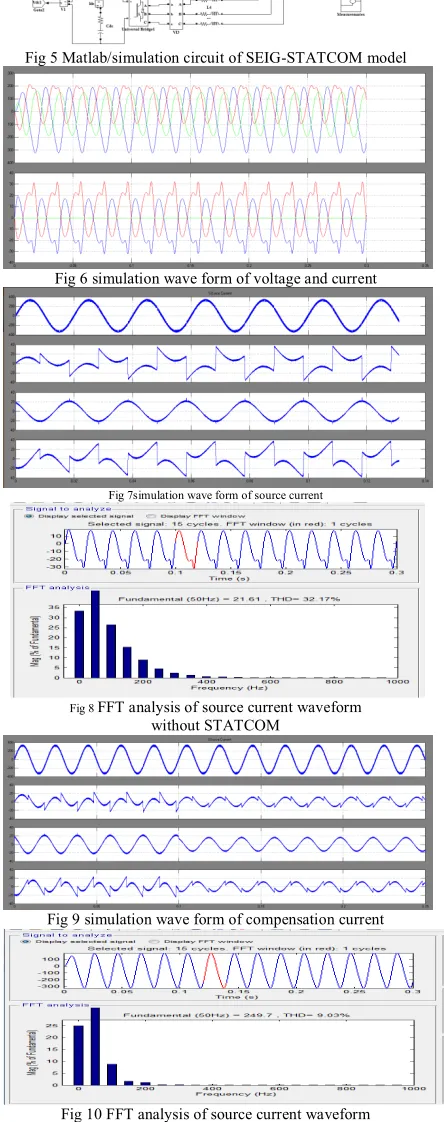
VI MATLAB/SIMULINK MODEL
Fig 5 Matlab/simulation circuit of SEIG-STATCOM model
Fig 6 simulation wave form of voltage and current
Fig 7simulation wave form of source current
Fig 8 FFT analysis of source current waveform without STATCOM
Fig 9 simulation wave form of compensation current
Available online:
http://edupediapublications.org/journals/index.php/IJR/
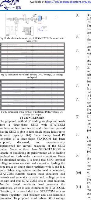
P a g e | 5225 Fig 11 Matlab/simulation circuit of SEIG-STATCOM model withwind DFIG
Fig 12 simulation wave form of wind DFIG voltage, Dc voltage and speed
Fig 13 simulation wave form of wind torque DFIG voltage, Dc voltage and torque
VI CONCLUSION
The proposed method of feeding single-phase loads
from a three-phase SEIG with STATCOM
combination has been tested, and it has been proved that the SEIG is able to feed single-phase loads up to its rated capacity. D-Q frame theory based PI controller of a three-phase STATCOM has been
proposed, discussed, and experimentally
implemented for current balancing of the SEIG system. Model of three phase SEIG-STATCOM is capable of simulating its performance while feeding single-phase loads under transient conditions. From the simulated results, it is found that SEIG terminal voltage remains constant and sinusoidal feeding the three-phase or single-phase rectifiers with R and R-L loads. When single-phase rectifier load is connected, STATCOM currents balance these unbalance load currents and generator currents and. voltage remain constant and thus STATCOM acts as load balancer. Rectifier based non-linear load generates the harmonics, which is also eliminated by STATCOM. Therefore, it is concluded that STATCOM acts as voltage regulator, load balancer and also harmonic eliminator. To proposed wind turbine DFIG voltage and current
REFERENCES
[1] Bhim Singh, Fellow, IEEE, S. S. Murthy,
Life Fellow, IEEE, and Raja Sekhara Reddy Chilipi,“STATCOM-Based Controller for a Three-Phase SEIG Feeding Single-Phase Loads”, IEEE transactions on energy conversion, vol. 29, no. 2, june 2014.
[2] C. Bansal, Senior Member, IEEE ,
“Three-phase self -excited induction generator : An overview,” IEEE transactions on energy conversion, vol. 20, no. 2, june 2005.
[3] Dhikra Chermiti, Adel Khedher, “A New
Method Voltage and Frequency Regulation of Self-Excited ” wseas transactions on environment and development Induction Generator Operating in Stand Alone
[4] G. Dastagir and L. A. C. Lopes, “Voltage and frequency regulation of a stand-alone self-excited induction generator,” in Proc. IEEE Electr. Power Conf., 2007, pp. 502– 506.
[5] H. Rai, A. Tandan, S. Murthy, B.Singh, and
B. Singh, “Voltage regulation of self excited induction generator using passive elements,” in Proc. IEEE Int. spp. 240– 245.
[6] L. Shridhar, B. Singh, and C. Jha, “Transient
performance of the self regulated short shunt self excited induction generator,” IEEE Trans. EnergyConvers., vol. 10, no. 2, pp. 261–267, Jun. 1995.
[7] E. Bim, J. Szajner, and Y. Burian, “Voltage
compensation of an induction generator with longshunt connection,” IEEE Trans. Energy Convers.,vol. 4, no. 3, pp. 526–530, Sep. 1989.
[8] L. Shridhar, B. Singh, C. Jha, B. Singh, and
S. Murthy, “Selection of capacitors for the self regulated short shunt self excited induction generator,” IEEE Trans. Energy Convers., vol. 10, no. 1, pp. 10–17, Mar. 1995.
[9] L. Wang and C.-H. Lee, “Long-shunt and
short-shunt connections on dynamic
performance of a SEIG feeding an induction motor load,” IEEE Trans. Energy Convers., vol. 15, no. 1, pp. 1–7, Mar. 2000.
[10] M. B. Brennen and A. Abbondanti, “Static exciters for induction generators,” IEEE Trans. Ind. Appl.,vol. IA-13, no. 5, pp. 422– 428, Sep. 1977.
[11] B. Singh, S. Murthy, and S. Gupta,
“STATCOMbased voltage regulator for
self-excited induction generator feeding
Available online:
http://edupediapublications.org/journals/index.php/IJR/
P a g e | 5226[12] E. Larsen, N. Miller, S. NiSsson and S.
Lindgren, "Benefits of GTObased
compensation systems for electric utility applications," IEEE Trans, on Power Delivery, Vol. 7, No. 4, pp. 2055-2064, October 1997.
[13] C. Schauder and H. Mehta, "Vector analysis and control of advanced static VAR compensator," IEE Proc.-C, Vol. 140, No. 4, pp.299-306, July 1993.
[14] T. Chan and L. L. Lai, “A novel single-phase selfregulated self-excited induction generator using a three-phase machine,” IEEE Trans. Energy Convers.,vol. 16, no. 2, pp. 204–208, Jun. 2001.