Time
Efficient Square and Cube
Architecture
using Vedic Sutras
Chinchu R
1, Nishi.G.Nampoothiri
2PG Scholar, Dept. o f ECE, Musaliar Co llege of Engineering and Technology, Pathanamthitta, Kera la, India1 Associate professor, Dept. of ECE, Musalia r College of Eng ineering and Technology, Pathanamthitta, Ke rala , India2
ABSTRACT: Ved ic Mathe matics is an ancient system of mathe matics. Square and cube are frequently performed functions in most of the DSP systems. The e xisting system of the thesis was based on low power square and cube architecture of 8 bit using Vedic sutras due to its frequent usage. Squaring utilised Duple x property properties of Urdhva Tiryagbhyam and cubing used Anurupyena sutra. The proposed system aimed at performing both these square and cube architectures using a single algorith m wh ich is time efficient and ha ve simple architecture based on Vedic mathe matics. The modified system enabled performing 4-bit mu ltip licat ion and addition besides 8-bit squaring and cubing. Thus the thesis comprises of a single architecture that can perfom addition, multip lication and also special case of multip licat ion that is square and cube of 8-bit numbers. It basically consists of a control unit and an arithmetic and logic unit. The control unit selects which operation is to be performed and accordingly the ALU unit functions and gives the result after the required number of c lock cyc les. The architecture is simp le and time e ffic ient.
KEYWORDS: Vedic Mathe matics , Urdhva Tiryagbhyam, Anurupyena sutra, Duple x property.
I.INTRODUCTION
Vedic mathe matics is the name given to ancient mathe matical system which was rediscovered fro m the Vedas by Sri Bharati Krishna Tirthaji between 1911 and 1918. The most important feature of the Vedic mathe matics system is its coherence. Instead of lengthy unrelated techniques the entire system is beautifully interrelated and unified. The general mu ltip licat ion method can be easily reversed to allow one-line div ision also the simple squaring method can be reversed to get one-line square root. All these methods can be easily understood. The unifying quality of this system is its highlight, this makes mathe matics easy and it will encourage innovation. In the past, conventional methods have been used for mult iplication. Conventional methods have been highly time consuming. Hea rt of many of the DSP operations like Decoding, Image Co mpression , Demodulation are cube and square architectures. It has numerous applications in cryptography also. Since many of the DSP sytems use square and cube operations it caused gre ater delay in the entire system.
The objective of this paper is to design a single architecture for performing square and cube operations due to the wide usage of these mathemat ical operations in many digita l signal processing systems as mentioned above. In the existing systems two architectures were used for square and cube operations.The main objectives of this thesis are Designing a single architecture for various mathemat ical operations such as 4-bit mu ltip licat ion and addition and 8-bit square and cube architecture. Other objectives include: architecture should be simp le as we ll as time efficient . When opting for the hardware imp le mentation it should be cost effective.The architecture should be consuming less area with respect to the e xisting designs.
II. RELATED WORKS
Various methods of operation are used to perform square and cube architecture using Ved ic mathe matics in previous studies included in this fie ld. They include:
2. Square can also be calculated using Duple x property of binary nu mbers wh ich is simila r to the Duple x property of decimal nu mbers present in Vedic mathe matics In this Duple x, ta ke twice the product of the outermost pair, then add twice the product of the next outermost pair, and till no pairs are left. If the number of bits is odd, one bit is left in the middle, enter it as such.
3. Ca lculat ion of cube is based on the Anurupya Sutra. It states that begin with the cube of first digit then take ne xt three numbers in Geo metrical Proportion then the 4th figure present at the right end will be the cube of the second digit. If a and b are two d igits, according to the Anurupya Sutra the result will be equal to (a +b)³[13].
4. Yavadunam Sutra can also be applied for performing squaring as well as cubing operations of a system. 5. Conventional 8-bit mu ltip lie rs, 4-bit mu ltip lie rs etc are replaced by Vedic mu lt ipliers as well.
III.MODIFIED S YSTEM
The work is main ly aimed at 8-b it square and cube architecture. Suitable modifications are done to the existing system which was based on dwandwa yoga property of urdhvatiryagbhyam sutra for squaring and Yavadunam Sutra for cubing inorder to confine both the operations in one architecture whereas separate architectures were required for square and cube in the every existing systems. Also the designing of the architecture was done carefully inorder to improve the timing efficiency of the system fro m the previous architectures for the square and cube operations. It uses basic operations like selection, shift ing, addition only. So the arch itecture is simple with mu x, adders, shifters etc. Along with 8-bit squaring and cubing this design will a lso perform 4-bit addition and multip licat ion. This forms the modified system.
IV.OVERVIEW OF THE MODIFIED S YS TEM
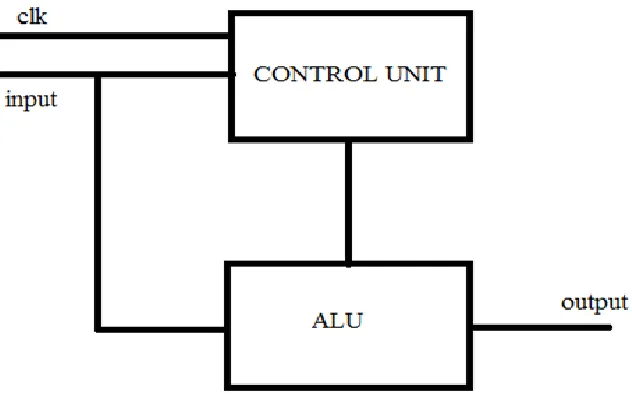
The modified system is composed of two important blocks. One is the control unit and the other one is the Arithmet ic and Logic Unit. As the name suggests the ALU performs the arithmetic operations and it is the control unit that determines which operation is to be performed. The overview of the system is shown in the figure 1.
Figure 1. Block diagra m of the proposed system
unit is provided with many commands. The command given to the control unit determines the operation to be performed by the arith metic and logic unit of the proposed design.
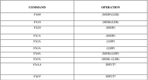
TABLE 1 COMMANDS AND OPERATION IN CU
COMMAND OPERATION
8‟h00 (MSB²)(LSB)
8‟h10 (MSB)(LSB)
8‟h20 (MSB³)
8‟h1A (MSB²)
8‟h2A (LSB³)
8‟h3A (LSB²)
8‟h4A (MSB)(LSB²)
8‟h5A (MSB)+(LSB)
8‟hAA INPUT²
8‟hFF INPUT³
ALU as the name suggests is the section which performs all the a rith metic operations of the design. It can perform 8-b it square and 8-bit cube operations from the single architecture which was the main objective of our proposed design. Besides this it can perform various 4-bit operations shown in the above table apart from the 8-b it operations. It can perform 4-bit addit ion, mult iplication, squaring and cubing operations. The selection of the operation is based on the commands given in the table 1.
V. ARCHIT ECTURE OF THE PROPOS ED S YSTEM
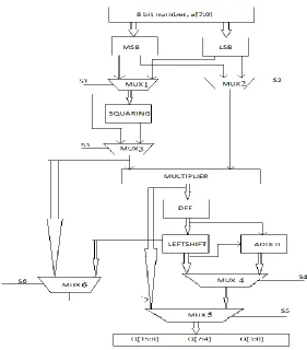
The figure 2 shown below is the algorithm showing the operation upto obtaining the partial products (MSB)(LSB),(MSB)²(LSB), (MSB)(LSB)², (M SB)², (LSB)²,(MSB)³, (LSB)³. The algorith m starts with initially storing the 8-bit input into a D-flipflop. The 8-b it input is then split into two 4-bit parts ie., 4-bit LSB and 4-bit MSB. This MSB and LSB are connected to two mult iple xers. This multip le xe rs according to the select lines S1 and S2 selects MSB or LSB. If S1 of MUX1 selects MSB then the output of the sq uaring section will be (MSB)² and is S1 of MUX1 selects LSB then its otput will be (LSB)². Simila rly according to the select line S2 of M UX2 the output of the mu ltip le xer will be (M SB) or (LSB). Then the output of the multip le xe r with select line S3 of MUX3 will be (M SB)² or (LSB)² or otherwise (MSB) o r (LSB). The output of MUX2 and MUX3 a re given to the vedic mu ltiplie r. Also the output of the MUX3 is also given to MUX6.
(MSB)²(LSB), (MSB)(LSB)², (MSB)², (LSB)²,(MSB)³, (LSB)³ or (MSB)(LSB). This value depends on the select line S1,S2,S3,S4,S5, S6.
Figure 2 A lgorith m showing partia l product of the proposed system
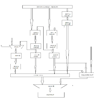
The 16-bit partia l product stored in the D flipflop as shown in Figure 2 is then coined with 6 zero bits in the MSB to form a 22 bit value and it is stored in a 22 bit DFF as shown in Figure 3. Consider the 22 bit number is Q[21:0], fro m this Q[11:0] is stored in DFF1. The output of DFF1 is stored in DFF2 inorder match with the time delay. Q[17:0] is stored in DFF4 along with [3:0] b its from the output of DFF2. The output of DFF4 is given to a ripple carry adder RCA2, the inputs to RCA2 are [7:0] bits of the output DFF4 and [21:8] bits of the output DFF4. The output of RCA2 is given as input to DFF3 a long with Q[21:18] as LSB. The output of DFF3 is given to RCA 1 by divid ing the input into [9:0]bits and [21:10] bits.
Figure 3 A lgorith m showing the operation of the proposed system
Thus, the 8-bit number is given as input as shown in figure 2 and a partial product is obtained as the output of the algorith m. Then it is given as input of the algorithm shown in figure 3 and we can obtain the final output at the end of operations as shown in the algorith m.
VI. RES ULTS
Figure 4 Proposed architecture along with 4-bit mu ltip lie r
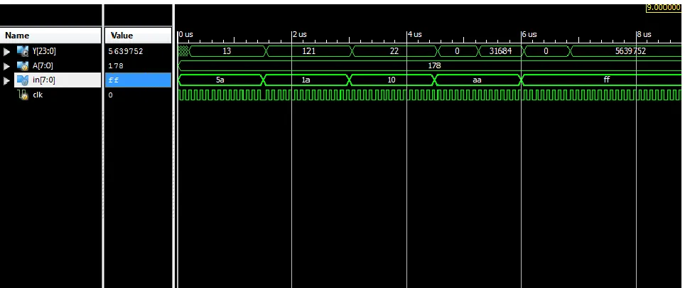
The fina l simu lation results of the proposed system shown in figure 5 inc ludes the 8-bit square and cube output and also the 4-bit mult iplication and 4-bit addition output of the system. . In the figure the result named A is the input given to the architecture, „in‟ represents the commands in the control unit, clk is the clock cycle and Y is the output of the e xisting square and cube architecture.
Figure 4 Proposed architecture along with 4-bit mu ltip lier and adder
of square and cube is 3ns only which has a higher margin than the conventional methods whose delays were 27ns and 41ns respectively.
Figure 5 Time delay co mparison graph of three systems
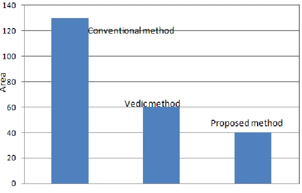
Synthesis reports shows that for calculating the cube of an 8-bit input the architecture utilizes 349 nu mber of LUTs. This LUTs are used for the calculation of cube operation alone. For calculating the square of an 8-bit input the architecture utilizes 58 number of LUTs. This LUTs are used for the calculation of square operation only. Thus for calculating square and cube simultaneously a total of 407 LUTs are required. For the proposed system,the architecture utilizes 349 nu mber of LUTs. This LUTs are used for the calculation of square,cube, multiplication and addition operations simultaneously. So the proposed system utilises less number of LUTs as compared to that of the existing system. Hence it uses less area than the previous architectures .
Figure 6 Area co mparison graph of three systems
VII.CONCLUS ION
In this work designing and the simu lation of a single a rchitecture for performing 8-bit square and 8-bit cube operations is main ly done. The system is designed in such a way to include multiplication and addition operation of 4-bit numbers also. The main purpose of the thesis is the time efficient operation of the design in order to increase the overall performance of the system utilising this design. Digital signal processing systems are the systems mainly utilising square and cube operations. It is the bottleneck of many of the DSP operations hence by increasing the speed o f square and cube operations we can imp rove the overall performance. The a im o f this project was to achieve two objectives. Firstly,to propose a new architecture to imp rove the timing efficiency of the square and cube operation. Secondly, to ensure that the both the operations is performed using a single architecture . A lso the architecture designed should be simp le and utilises less area. In contradiction to the previous systems square and cube operations were done using a single architecture which is time effic ient, simple and consumes less area.
REFER ENC ES
[1] Albert A. Liddicoat and Michael J. Flynn, "Parallel Square and Cube Computations", 34th Asilomar Conference on Signals, Systems, and Computers, California, October 2000.
[2] Aniruddha Kanhe, Shishir Kumar Dasand Ankit Kumar Singh, “Design and Implementation of Low Power Multiplier using Vedic Multiplication Technique”, International Journal of Computer Science and Communication, Vol. 3, No. 1, June 2012, pp. 131-132.
[3] Anju and V.K. Agrawal, “ FPGA Implementation of Low Power and High Speed Vedic Multiplier using Vedic Mathematics”, IOSR Journal of VLSI and Signal Processing (IOSR-JVSP) Volume 2, Issue 5 Jun. 2013, ISSN: 2319 – 4200, pp. 51-57.
[4] B. Dilli kumar , M. Bharathi ,A high speed and efficient design for binary number squaring using dwandwa yoga; International Journal of Advanced Computer Science and Applications,Volume 1, Issue 4, June 2012
[5] H. D. T iwari, G. Gankhuyag, C. M. Kim, and Y. B. Cho, Multiplier design based on ancient Indian Vedic Mathematics; Vol. 2, Issue 12, December 2013
[6] Jagadguru Swami Sri Bharath, Krsna T irathji, “Vedic Mathematics or Sixteen Simple Sutras From The Vedas”, Motilal Banarsidas , Varanasi (India),1986.
[7] Kunchigi, V.; Kulkarni, L.; Kulkarni, S., "High speed and area efficient vedic multiplier," Devices, Circuits and Systems (ICDCS), 2012 International Conference on , vol., no., pp.360,364, 15 -16 March 2012
[8] Himanshu Thapliyal, S. Kotiyal and M.B. Srinivas, “ Design and Analysis of a Novel Parallel Square and Cube Architecture Based on Ancient Indian Vedic Mathematics”, Proceedings on 48th IIEEE International Midwest Symposium on Circuits and Systems (MWSCAS 2005)
[9] Kabiraj Sethi, Rutuparna Panada, “An Improved Squaring Circuit for Binary Numbers” , International Journal of Advanced Computer Science and Applications, Vol. 3, No. 2, 2012.
[10] Premananda B.S, Samarth S. Pai, Shashank B, Shashank S. Bhat, Design and Implementation of 8 -Bit Vedic Multiplier, International Journal of Advanced Research in Electrical, Electronics and Instrumentation Engineering Vol. 2, Issue 12, December 2013
[11] Rakshith T R and RakshithSaligram, “Design of High Speed Low Power Multiplier using Reversible logic: a Vedic Mathematic al Approach”, International Conference on Circuits, Power and Computing Technologies (ICCPCT-2013), pp.775-781.
[12] Swami Bharati Krisna Tirtha, “Vedic Mathematics,” Motilal Banarsidass Publishers, Delhi, 1965.