Available Online atwww.ijcsmc.com
International Journal of Computer Science and Mobile Computing
A Monthly Journal of Computer Science and Information Technology
ISSN 2320–088X
IMPACT FACTOR: 6.017IJCSMC, Vol. 8, Issue. 3, March 2019, pg.291 – 305
A Comparative Study on
Representing RDF as Graph
and Hypergraph Data Model
Fayed F. M. Ghaleb
1; Azza A. Taha
2; Maryam Hazman
3;
Mahmoud M. Abd ElLatif
4; Mona Abbass
5¹
Department of Mathematics, Faculty of Science, Ain Shams University Cairo, Egypt²
Department of Mathematics, Faculty of Science, Ain Shams University Cairo, Egypt ³Agricultural Research Center, Giza, Egypt4
College of Business, University of Jeddah, SA, Faculty of Computers and Information, Helwan, Cairo, Egypt
5
Agricultural Research Center, Giza, Egypt
1
[email protected]; [email protected]; [email protected];
4
[email protected]; [email protected]
Abstract— The semantic web gives a common framework that enables data to be shared and reused crosswise communities and applications. Semantic web depends on Resource Description Framework (RDF) graph data model, which is a standard model for data interchange on the web. Therefore, the success of the semantic web mainly relies upon the good creation of RDF. A powerful representation formalism for both structured and unstructured data are graphs that can be seen as a unified data representation. Also the development of the semantic web requires accessing large quantities of data stored in relational databases (RDB). Making data hosted in RDB machine understandable to the semantic web has been an active field of research during the last decade. Some of graph models that are used for representing an RDF succeed to solve some problems like blank nodes, reification, and answering queries posed by users and software agents, but fails in other problems like semantic reasoning and RDF query evaluation techniques. Also in the area of representing RDB as RDF graph data model none of these models defined a formal model for RDF graph model. Some database features like the normalization, function dependency, and query optimization does not address in the current graph representations. The purpose of this study is to present the important contributions that have been produced in the area of representing RDF as graph and hypergraph data model. Two models for representing relational database as an RDF graph data model are also reviewed.
I. INTRODUCTION
A. The Development of the Semantic Web
The World Wide Web was essentially designed for human utilization, and although everything on it is machine-readable, the data is not machine-understandable [1]. A new approach to manage data and process was provided by the semantic web and semantic web technologies; the principle idea of the semantic web is the creation and utilization of semantic metadata [2].
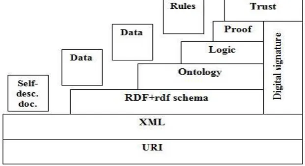
The development of the semantic web proceeds in steps, each step builds a layer on top of another. Fig.1 shows the “layer cake” of the semantic web, which describes the main layers of the semantic web design and vision. The Uniform Resource Identifier (URI), at the bottom of the layer cake of the semantic web is considered to be the foundation of the web [3]. It is used for identifying and locating resources. It is also used for giving a unique name to each resource.
The Extensible Markup Language (XML), is a language that helps to write structured web documents with a user-defined vocabulary. It is particularly suitable for sending documents across the web.
The Resource Description Framework (RDF) is a basic data model for writing simple statements about web resources. It is used for expressing data about data resources on the semantic web [4]. This data is suitable for processing by applications and therefore it becomes the base of the semantic web [5]. The RDF data model, in figure 1 does not rely on XML, but it has an XML-based syntax. Therefore, it is located on the top of the XML layer.
The RDF Schema (RDFS) provides modeling primitives for organizing web objects into hierarchies. Its key primitives are classes, properties, subclass, subproperty relationships, domain, and range restrictions. RDF schema is based on RDF. The semantic web initiative [6] purposes for giving internet-wide standards for semantically improving and describing web resources using the standards RDF and RDF-Schema RDFS.
The RDF schema can be viewed as a primitive language for writing ontologies.
The Logic layer is used for enhancing the ontology and allows writing applications specific to declarative knowledge.
The Proof layer involves the actual deductive process as well as the representation of proofs in web languages (from lower levels) and proof validation.
Finally, the Trust layer will arise through using digital signatures and other kinds of knowledge, which is based on recommendations by trusted agents or on rating and certification agencies and customer bodies.
Fig. 1 A layered approach of the semantic web.
B. The Structure of RDF
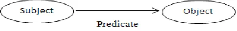
The RDF statements are triples <Sub><Pred><Obj>,
consisting of three parts a subject <Sub>, a predicate <Pred>, and an object <Obj>.
Where the subject is the resource to be described, the predicate is a property, and the object is a property’s value. For example, The RDF statement
<Ahmed><is_a><person>,
Gives “Ahmed” as the subject of the triple, "is_a" as the predicate of the triple, and ” person” as the object of the triple.
Fig. 2 Graphic representation of an RDF triple.
There is another representation of RDF triple, which is based on XML. An RDF document is represented by an XML element with the tag rdf:RDF. The content of this element is a number of descriptions, which use rdf:Description tags. Each description makes a statement about a resource, which is identified in one of the following three different ways:
An ID attribute, creating a new resource.
Without a name,i.e., creating an anonymous resource.
An about attribute, referencing an existing resource as follows:
<? xml version="1.0" encoding="UTF-16"?> <rdf:RDF
xmlns:rdf="http://www.w3.org/1999/02/22-rdf-syntax-ns#" xmlns:mydomain="http://www.mydomain.org/my-rdf-ns">
<rdf:Description rdf:about=" person "> <mydomain: is_a rdf:resource="#Ahmed"/>
</rdf:Description> </rdf:RDF>
The above representation shows that the graph model is more suitable data model to represent RDF and that XML is just a possible representation of such graph.
One of the primary features of the RDF_graph model is its ability to interconnect resources of the RDF in an easy way. The basic notions of graph theory like node, edge, path, neighborhood, connectivity, distance, and degree play a central role in expressing RDF with graph-like structure.
Introducing graphs as a modelling tool for a connected data has many advantages. Graphs overcome the big and complex data challenges that other database cannot. Graph structures permit a natural way of handling applications data and also can be visible to the user. Queries might be referring directly to this graph structure. Associated with graphs will allow the using of operations in the query language algebra, such as finding shortest paths, determining certain subgraphs [8]. Moreover, graph traversals over extremely connected data demand complex join operations, which can make typical operations on this type of data inefficient and applications tough to scale [9, 10].
There are many problems need to be solved in representing the RDF as graph data model like:
Semantic reasoning to discover relationships between resources.
Reification to make statements about other statements, such as Mona believes that Yasmine likes pets. Reification is a good example to see that any property is also an information resource which can be the subject or object of descriptions.
The existence of the blank nodes.
Answering queries posed by users and software agents.
C. The RDF and Relational Database
One of the goals of the semantic web is to display the huge quantities of data that is stored in the relational databases for computer processing. In order to integrate relational databases into semantic web applications, relational databases should be represented as RDF. Representing relational database as RDF is fundamental for developing the semantic web in the recent decade [11].
Some of graph models that are used for representing an RDF solved some problems like blank nodes, reification, and answering queries posed by users, and none of these models studied problems like semantic reasoning and RDF query evaluation techniques. Also All works that have been proposed to convert RDB into RDF are depending on converting the data that stored in the relational model not the schema, and none of these works define the RDF as graph model. Also an efficient conversion of a relation database is depending on satisfying all database features like referential integrity, normalization, reusability, function dependency, information preservation, query preservation, and semantics preservation. Some of these features have been satisfied by the current approaches.
graphs and hypergraphs are given. Section 3 contains the methodology of representing RDF document as graph and hypergraph data model and two models of representing database as RDF graph data model. Section 4 illustrates the conclusions of the paper.
II. PRELIMINARIES
In this section, the basic mathematical definitions of graphs and hypergraphs are given [12] - [16].
A. Graphs
Definition 1: A graph
G
is a pair(
N
,
E
)
, whereN
is a set of nodes, andE
is a set of edges. Each edgeE
e
is an unordered pair{
u
,
v
}
,u
,
v
N
. For example, Fig. 3, shows a graph with set of edges}
,
,
,
,
{
e
1e
2e
3e
4e
5E
, wheree
1
{
A
,
B
}
,e
2
{
B
,
C
}
,e
3
{
C
,
D
}
,e
4
{
A
,
C
}
,e
5
{
B
,
D
}
, and set of nodesN
{
A
,
B
,
C
,
D
}
.Definition 2: Two edges
e
1,e
2 are said to be incident if they share a node; i.e.e
1
e
2
. For example, the two edgese
1,e
2 of Fig. 3 are incident.Definition 3: The degree of a node
n
, denoted degree (n), is the number of edges incident to it. For example, the degree of the nodeA
of Fig. 3 is 2.Definition 4: A graph
G
'
(
N
',
E
')
is a subgraph of a graphG
, denotedG
'
G
, ifN
'
N
, andE
E
'
. Fig. 4 shows thatG
'is a subhgraph of the graph in Fig.3, where the set of nodesN
'
{
A
,
B
,
C
}
and the set of edges{
1,
2,
3}
'
e
e
e
E
.Definition 5: A graph
G
(
N
,
E
)
is said to be bipartite graph ifN
U
V
, whereU
V
and for all{
u
,
v
}
E
it holds thatu
U
andv
V
. A bipartite graph is regular if for everyv
1,
v
2
V
,degree ( =degree ( ). For example, Fig. 5 shows a bipartite graph with set
U
{
u
1,
u
2,
u
3,
u
4,
u
5}
, set}
,
,
,
{
v
1v
2v
3v
4V
andU
V
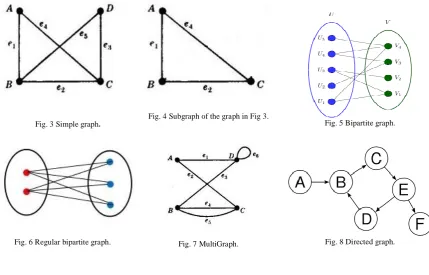
and Fig. 6 shows a regular bipartite graph.Fig. 3 Simple graph. Fig. 4 Subgraph of the graph in Fig 3. Fig. 5 Bipartite graph.
Definition 6: A graph
G
is a multigraph if multiple edges are permitted between two nodes. For example, Fig. 7, shows a multigraph with six edges{
e
1,
e
2,
e
3,
e
4,
e
5,
e
6}
, wheree
1
{
A
,
D
}
,e
2
{
A
,
C
}
,e
3
{
B
,
D
}
,}
,
{
4
B
C
e
,e
5
{
B
,
C
}
, ande
4
{
D
,
D
}
,N
{
A
,
B
,
C
,
D
}
and two multi edgese
4ande
5 between nodesB
andC
.Definition 7: A directed graph or digraph
D
is an ordered pair(
N
,
E
)
withN
is a set of nodes, andE
a set of ordered pairs of nodes, called edges, directed edges, or arrows as shown in Fig. 8. An edgee
between two nodesA
andB
is an ordered pair(
A
,
B
)
, and is considered to be directed fromA
toB
;B
is called the head andA
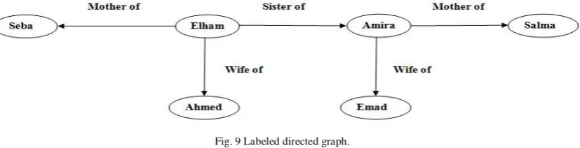
is called the tail of the edge.Definition 8: A graph
G
(
N
,
E
)
is said to be edge-labeled when there is an edge label setL
Eand an edge labeling functionl
E:
E
L
E, such thatl
E(
e
)
e
i,
e
E
ande
i
L
E. A graph is said to be node-labeled when there is a node label setL
N and a node labeling functionl
N:
N
L
N , such thatN
n
n
n
l
N(
)
i,
andn
i
L
N. The notation(
N
,
E
,
l
N,
l
E)
will be used for an edge-node-labeled graph. For example, Fig. 9 shows a labeled graph with set of nodesN
{
n
1,
n
2,
n
3,
n
4,
n
5,
n
6}
,Node labeling function
l
N
{
Seba
,
Elham
,
Amira
,
Salma
,
Ahmed
,
Emad
}
, set of edges}
,
,
,
,
{
e
1e
2e
3e
4e
5E
, and edge labeling function}
,
,
{
Motherof
Sisterof
Wifeof
l
E
.Definition 9: A path in a graph
G
(
N
,
E
)
is a sequence of edgese
1,...,
e
n, where each edgee
iis incidentto
e
i1, for1
i
n
. A path is said to be simple if it additionally holds thate
i
e
jfori
,
j
n
,i
j
. For example,(
e
1,
e
2,
e
3)
is the simple path from nodeA
to nodeD
in the graph of Fig. 3.Definition 10: Two nodes
x
,
y
are connected if there exists a pathe
1,...,
e
n, withx
e
1andy
e
n. Thelength of a path is the number of edges it contains. For example, the length of the path
(
e
1,
e
2,
e
3)
from nodeA
to node
D
in the graph of Fig. 3 is 3.Definition 11: The label of the path in an edge-labeled graph is the concatenation of the edge labels the path
n
e
e
1,...,
consists of:l
e
l
e(
e
1).
l
e(
e
2)....
l
e(
e
n)
. For example, the label of the path from nodeElham
to the nodeSalma
in the graph of Fig. 9 is(
Sisterof
.
Motherof
)
.B. Hypergraphs
Definition 12: A hypergraph
H
is a pair(
N
,
E
)
, whereN
a finite set of nodes andE
P
(
N
)
is a set of edges (or hyperedges) which are arbitrary nonempty subsets ofN
. Eache
E
is a set of nodes{
v
1,...,
v
n}
, wherev
i
N
.Brault-Baron [14] introduced an equivalent definition of the hypergraph as follows:
Definition12': A hypergraph
H
is a finite set of non-empty finite sets, called its hyperedges (or simply edges), the setN
(
H
)
of nodes of a hypergraphH
, is defined to be the union of all its hyperedges.For example, Fig. 10, shows a hypergraph with four edges
{
e
1,
e
2,
e
3,
e
4}
, wheree
1
{
A
,
B
,
C
}
,}
,
,
{
2
C
D
E
e
,e
3
{
E
,
F
,
A
}
, ande
4
{
A
,
C
,
E
}
, andN
(
H
)
{
A
,
B
,
C
,
D
,
E
,
F
}
.Definition 12 is equivalent to definition 12' when adding the following condition to definition 12:
N
v
e
E
, such thatv
e
That is when studying hypergraph notion, the possibility of having an empty edges can be excluded. The basic idea is that the empty edge cannot play a role in a graph. Also, there is no reason to consider the case where some vertices are contained in no edge. By excluded these cases, there is no need to define the set of nodes
N
separately; it can instead be inferred fromE
, i.e.,N
is defined as the union of all the graph edges. Therefore the hypergraph can be defined by only a set of non-empty edges.Definition 13: The size of a hypergraph
|
H
|
is defined to be the number of edges in it. For example, the size of the hypergraphH
in Fig. 10 is 4.Definition 14: The size of an edge
|
e
|
is defined to be the number of nodes in it. For example, the size of any edge in the hypergraph of Fig.10 is 3.Definition 15: A hypergraph
H
'is said to be a subhypergraphof a hypergraphH
ifH
'
H
.Note that, the subhypergraph
H
', inH
'
H
, is obtained fromH
by removing edges, and not removing nodes from edges. Figure 11 shows thatH
'
{
e
1,
e
2,
e
3}
is subhypergraph of the hypergraph in Fig. 10, where)
(
)
(
H
N
H
'N
.Fig. 10 An undirected hypergraph. Fig. 11. A subhypergraph of the hypergraph in Fig. 10.
III. METHODOLOGY
The aim of this paper is to study the various graph models that is used to represent RDF. Two models for representing relational database as an RDF graph data model are also reviewed.
A. The RDF Document
The elements of an RDF triple, <Sub><Pred><Obj> can be:
Uniform Resource Identifiers URIs, representing information resources,
Literals, which used for representing values of some data type, and
Blank nodes, which represent anonymous resources.
There are restrictions on the subject and predicate of a triple: the subject cannot be a literal, and the predicate cannot be a blank node. Note that, resources, blank nodes and literals are sometimes referred to as triple values.
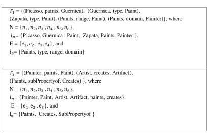
TABLE 1
THE RDF 𝑇 and 𝑇[12].
𝑇 = {(Picasso, paints, Guernica), (Guernica, type, Paint),
(Zapata, type, Paint), (Paints, range, Paint), (Paints, domain, Painter)}, where
N = { },
= {Picasso, Guernica , Paint, Zapata, Paints, Painter },
E = { }, and
= {Paints, type, range, domain}
𝑇 = {(Painter, paints, Paint), (Artist, creates, Artifact),
(Paints, subPropertyof, Creates) }, where
N = { },
= {Painter, Paint, Artist, Artifact, paints, creates},
E = { }, and
= {Paints, Creates, SubPropertyof }
An RDF_graph
T
is a representation of a set of RDF triple. There are many graph models used to represent an RDF_graphT
:1) The Directed Labeled Multigraph Model: Hayes et. al [12] formalized the definition of directed labeled multigraph representing an RDF_graph
T
in the following definition:Definition 16: The node-edge-labeled multigraph
(
T
)
(
N
,
E
,
l
n,
l
e)
where,)}
(
)
(
:
{
v
x
sub
T
obj
T
N
x
,x
v
l
n(
x)
, and}
)
,
,
(
:
{
e
(, , )s
p
o
T
E
s po
, such that there is an edgee
fromv
s tov
o,l
e(
e
(s,p,o))
p
[12]. Fig. 12shows the node-edge-labeled multigraph for the RDF
T
1.Fig. 12 The node-edge-labeled multigraph for the RDF
T
1. Fig. 13 An RDF graph extending the notion of edge.Note that, the set of edge labels and node labels might not be disjoint such as paints in Fig. 13.
The
sub
(
T
)
(resp.pred
(
T
)
,obj
(
T
)
is used to designate all values which occur as subject (resp. predicate, object) ofT
.Definition 18: Let
V
be a set of URIs and literal values, thenRDFG
(
V
)
:
{
T
|
T
is RDF_graph and}
)
(
T
V
vocap
, i.e. the set of all RDF_graphs with a vocabulary included inV
[12].The number of nodes and edges for directed labeled multigraphs
T
is|
N
|
2
|
T
|
and|
E
|
|
T
|
,O
(|
T
|)
is the required space complexity to store the RDF triples represented byT
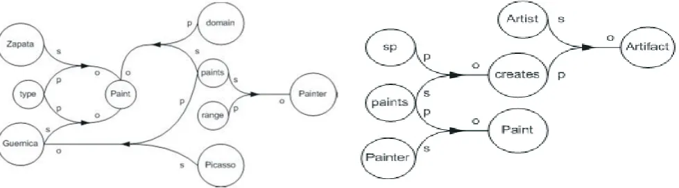
using this model [17].The directed labeled multigraph representation of RDF has two fundamental disadvantages. First, a resource may simultaneously appear as a predicate, a subject and/or an object in the same RDF_graph, this situation can be modeled by allowing a multiple occurrences of the same resource in the resulting labeled directed graph, as edges or nodes labels like paints in Fig. 12. Second, a predicate may relate other predicates in an RDF graph. Also this situation can be modeled by extending the notion of edge by allowing the connection between edges, but the result is not a graph according to the mathematical definition. For example, Fig. 13 shows the RDF graph
T
2 , where the predicate subPropertyOf relates the predicates paints and creates.Thus, while labeled directed multigraph model is the most widely used representation, it cannot be considered a formal model for RDF.
2) The Undirected Hypergraph Model: In the undirected hypergraph model, each RDF triple
T
o
p
s
,
,
)
(
, is a hyperedge in the RDF_graphT
, and each element is a node as shown in Fig. 14 [18]. The number of nodes and hyperedges for undirected hypergraphs RDF_graphsT
satisfy|
N
|
|
univ
(
T
)
|
and|
|
|
|
E
T
[18],O
(max(|
univ
(
T
)
|,
|
T
|))
is the required space complexity to store the RDF triples represented byT
using this model. Fig. 15 shows the undirected hypergraph representing the first three statements of RDFT
1. This representation has two disadvantages. First, the concept of direction in RDF_graphs is lost in this representation, which impacts the task of semantic reasoning. Secondly, it may be difficult to graphically represent huge RDF_graphs.3) The Bipartite Graph Model: Hayes et. al [12] introduced a representation of the RDF_graph by mapping RDF_graph into bipartite graphs. In the bipartite graph model, there are two types of nodes in
N
: statement nodesSt
(one for each RDF triple(
s
,
p
,
o
)
T
) and value nodesVal
(one for each element)
(
T
univ
n
), i.e.,N
St
Val
.Edges in
E
relate statement and value nodes as follows: eacht
St
has three out-coming edges that point to the corresponding node for the subject, predicate, or object of the RDF triple represented by the statement nodet
, which represented by circle as shown in Fig. 16.The number of nodes and edges of bipartite graphs satisfy
|
St
|
|
T
|
,|
Val
|
|
univ
(
T
)
|
, and|
|
3
|
|
E
T
,O
(max(|
univ
(
T
)
|,
|
T
|))
is the required space complexity to store the RDF triples represented byT
using this model.Representing RDF_graph as bipartite graph triple syntax has several advantages over the triple representation of the directed labeled multigraph representation. First, in the context of RDF, one the most important problem is the connectivity between two resources, and identifies the sequences of RDF statements that connected them. Using the bipartite graph model, graph connectivity is formalized, which allows these resources to be connected. Graph connectivity is essential for querying RDF and finding complex semantic association; the relation between two resources can be deduced from the collection of paths through the graph of RDF statements. Second, representing RDF_graphs as bipartite graphs highlights the graph-nature of RDF, and increase the possibility of using the standard graph libraries. Fig. 17 shows the bipartite graph representing the
first three statements of RDF
T
1. While bipartite graphs satisfy the requirement of a formal graph representation for RDF, there are some issues that have not been addressed like reification and semantic reasoning.Fig. 16 Bipartite graph for an RDF triple
)
,
,
(
s
p
o
.
Fig. 17 The Bipartite graph for the first three statements of the RDF
T
1.4)The Directed Hypergraph Model: Antonio et. al [19] proposed a directed hypergraph formal model to represent and manage RDF documents efficiently. In a directed hypergraph model, each RDF triple
T
o
p
s
,
,
)
(
, is a hyperedge in the RDF_graphT
, and each element of the RDF triple is a node. Each edgeE
e
has a directed labels
if the head node representing the subject of the triple,p
if the head node representing the property of the triple, ando
if the tail node representing the object of the triple. Thus the information is only stored in the nodes, and the hyperedge only preserve the role of each node and the concept of direction of RDF graphs. Fig. 18 shows the directed hypergraph for RDF_graphT
1, where paints stored only once even though it has tworoles as a subject and as predicate.The number of nodes and edges of directed hypergraph satisfy
|
N
|
|
univ
(
T
)
|
and|
E
|
|
T
|
,|))
|
|,
)
(
(max(|
univ
T
T
O
is the required space complexity to store the RDF triples represented byT
using this model.An advantage of this representation is that each resource (subject, property, or value) is stored only once. Therefore the space required to store an RDF document is reduced if a resource appears several times in the document [20]. Also this model allows a predicate to relate other predicates in an RDF_graph as shown in Fig. 19. In addition, concepts, techniques, and algorithms of hypergraph theory may be used to manipulate RDF_graphs under this representation using Simple Protocol and RDF Query Language (SPARQL) [21, 22]. While directed hypergraph satisfies the requirement of a formal graph representation for RDF, there are issues that have not been addressed such as reification, blank nodes, and semantic reasoning.
Fig. 18 The directed hypergraph for the first three statements of the RDF graph
T
1.Fig. 19 The directed hypergraph for the RDF_graph
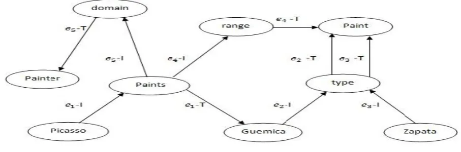
T
2.and object then every initial edge is mapped to its terminal edge. In LDM-3N each predicate is mapped to nodes instead of edges, and the nodes within the same triple are interconnected by a pair of initial and terminal edges. Fig. 20 shows LDM-3N for the RDF graph
T
1.The number of nodes and edges of directed hypergraph satisfy
|
N
|
|
univ
(
T
)
|
and|
E
|
2
|
T
|
,|))
|
|,
)
(
(max(|
univ
T
T
O
is the required space complexity to store the RDF triples represented byT
using this model.An advantage of this representation is that two types of paths are defined namely, resource path and triple path with a new traversal algorithm. The traversal algorithm is used for finding the shortest resource path and making querying RDF easier. While LDM-3N satisfy the requirement of a formal graph representation for RDF, there are issues have not been addressed such as blank nodes, and semantic reasoning.
Fig. 20 Labeled directed multigraph with triple nodes for the first three statements of the RDF graph
T
1.Table 2 Summarizes the difference between the different RDF graph representations.
TABLE 2
THE DIFFERENT REPRESENTATIONS OF RDF AS GRAPH MODELS “
√
” INDICATES SUPPORT.Directed Labeled Multigraph
Model
Undirected Hypergraph Model
Bipartite Graph Model Directed Hypergraph Model
LDM-3N
Number of
Nodes
|
N
|
2
|
T
|
|
N
|
|
univ
(
T
)
|
|
N
|
|
T
|
|
univ
(
T
)
|
|
N
|
|
univ
(
T
)
|
|
N
|
|
univ
(
T
)
|
Number ofEdges
|
E
|
|
T
|
|
E
|
|
T
|
|
E
|
3
|
T
|
|
E
|
|
T
|
|
E
|
2
|
T
|
Space
Complexity
O
(|
T
|)
|)) | |, ) (
(max(|univT T
O O(max(|univ(T)|,|T|)) O(max(|univ(T)|,|T|)) O(max(|univ(T)|,|T|))
Reification √ x x x √
Blank Nodes x x √ x x
Semantic Reasoning
x x x x x
Formal Graph Model
x x √ √ √
Answer Query
B. Representing Relational Database as RDF Graph
The main elements of the relational database model are:
Relations, which is defined as tables.
Attributes, which is defined as columns of a table. Each attribute belongs to a given relation and has data types. The primary key of the relation is used for identifying this relation’s tuples. A foreign key for a given relation, which also called parent relation, is a set of attributes that reference a tuple in another relation, called child relation.
Domains, which are sets of atomic constant values. Each attribute is related to a specific domain and all of its values are members of this domain.
A relational database uses a standard user and application program interface called Structure Query Language (SQL), which uses statements to access and retrieve queries from the database. Codd [24] has defined relational database schemes as a collection of table skeletons, while a relational database instance is a set of relation instances, one for each relation schema in the database schema.
Definition 19: A database scheme
R
{
R
1,...,
R
p}
, with relation schemesR
i
(
A
i,
D
i)
andi
i
,...,
p
,can be viewed as hypergraph
H
{
R
1,...,
R
P}
where{
R
1,...,
R
P}
are its hyperedges andN
(
H
)
ip1A
i, where eachA
i is the set of attributes andD
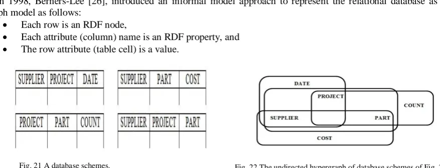
i is a set of domains. For example, the hypergraph of Fig. 22 corresponds to the database schemes of Fig. 21 [16].Definition 20: Let
N
be the set of attributes of a RDB. A Functional DependencyF
(
X
,
Y
)
, with bothX
and
Y
subsets ofN
, defines uniquely the value of the attributes inY
once the value of the attributes inX
is given [25].One of the most important steps of database scheme design is a normalization step, which minimizes the redundancy of stored information, and is based on functional dependencies.
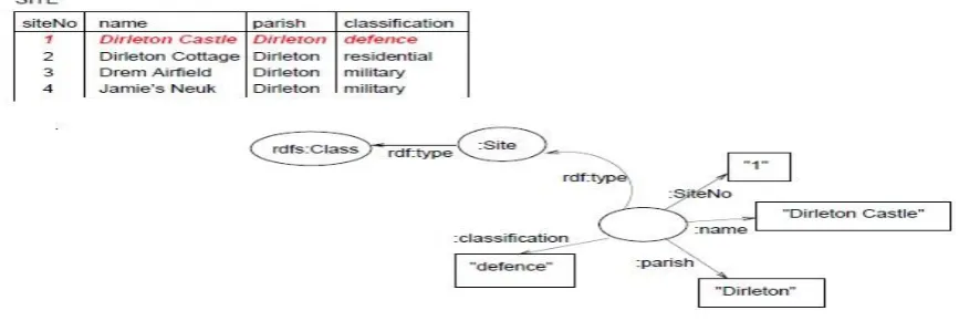
In 1998, Berners-Lee [26], introduced an informal model approach to represent the relational database as graph model as follows:
Each row is an RDF node,
Each attribute (column) name is an RDF property, and
The row attribute (table cell) is a value.
Fig. 21 A database schemes. Fig. 22 The undirected hypergraph of database schemes of Fig. 21.
Applying this set of rules automatically generate mappings between RDB and RDF_graph model, which called a directed mapping.
Fig. 23 Translation of a relational table tuple to RDF_directed graph.
Byrne [27], presented The Simple Knowledge Organization System (SKOS) framework, which is used to transform the Royal Commission on the Ancient and Historical Monuments of Scotland (RCAHMS) thesauri to the semantic web. In SKOS framework the size of the RDF dataset has been reduced as follows:
The blank nodes is replaced by a URI based on the surrogate RDB key, the literals are now resources with URIs and labels, and the database columns have become RDF classes in a class hierarchy.
In the case of one-to-many relational joins the redundant “key to key” triples can be pruned, when the linking keys have no intrinsic properties of their own.
In the case of in a many-to-many relationship the redundant RDF nodes, which represent the name of the bridge table can be replaced by a new predicate.
Avoiding duplication of schema metadata by repeating provenance information in the subject node, predicate arc and object node (unless the object is a literal) of a given triple. He also transposing edges and nodes by using “Column as Predicate” method, which turns RDB columns into classes or “nouns”, as they are in fact “things” with a hierarchical class structure. Reducing graph size makes a colossal difference to performance in terms of storage, loading and query times.
While, Byrne solved a lot issues in representing RDB as RDF_graph but issues like define a formal model for RDF graph model, Function dependency, and Normalization have not been addressed yet.
There are several approaches for addressing the issue of mapping from relational databases to RDF namely Direct mapping [26, 28-31], Domain Semantics-Driven mapping [32-39], and Mapping language D2R [40], R2O [41, 42], D2RQ [43], Relational.OWL [44], D2R Server [45], Virtuoso [46, 47] DB2OWL [48], Triplify [49], D2RQ Platform [50], R2RML [51], R3M [52] , RDB2Owl [53], and xR2RML [54].
All these approaches are depending on converting the data that stored in the relational model not the schema, and satisfying some database features like entity integrity, which is crucial to preserving valid relationships between tables and data within a database. For instance, referential integrity; can be used to ensure foreign key values are valid [55], reusability, information preservation; if it does not lose any information about the relational instance being translated, that is, if there exists a way to recover the original database instance from the RDF graph resulting from the translation process, and query preservation; if every query over a relational database can be translated into an equivalent query over the RDF graph resulting from the mapping. That is, query preservation ensures that every relational query can be evaluated using the mapped RDF data, and semantics preserving if the satisfaction of a set of integrity constraints are encoded in the mapping result.
IV. CONCLUSIONS
The World Wide Web has changed the way people communicate with each other and the way business is conducted. Most of today’s web content is suitable for human consumption. The semantic web is an initiative that aims to improve the current state of the World Wide Web and make data understandable.
Semantic web depends on RDF graph data model, which is a standard model for data interchange on the web. Therefore, the success of the semantic web mainly relies upon the good creation of RDF.
In the area of representing RDF as graph data model, some of graph models that are used for representing an RDF solved some problems like blank nodes, reification, and answering queries posed by users, and none of these models studied problems like semantic reasoning and RDF query evaluation techniques.
A simple query in SPARQL is based on graph patterns, and query processing consists of the binding of variables to generate pattern solutions (graph pattern matching) [57].
Even web content that is generated automatically from databases is usually presented without the original structural information found in databases. Making data hosted in relational databases RDB machine understandable to the semantic web has been an active field of research during the last decade [11].
In the area of representing RDB as RDF graph data model, there are only two models for representing RDB as RDF_graph data model, but none of them define a formal RDF graph model. There are also several approaches for addressing the issue of mapping from RDB to RDF. All works that have been proposed to convert RDB into RDF are depending on converting the data that stored in the relational model not the schema, and none of these works define the RDF as graph model. Also an efficient conversion of a relation database is depending on satisfying all database features like referential integrity, normalization, reusability, function dependency, information preservation, query preservation, and semantics preservation. Some of these features have been satisfied by the current approaches like entity integrity, reusability, information preservation, semantics preserving, and query preservation. There are some features like the normalization, function dependency, and query optimization does not address in the current approaches.
R
EFERENCES
[1] O Lassila., and R. Swick (1999) Resource Description Framework (RDF) Model and Syntax Specification. [Online]. Available: https://www.w3.org/TR/rdf-syntax-grammar/.
[2] J. Davies, R. Studer, and P. Warren, Semantic Web Technologies Trends and Research in Ontology-based Systems,1st ed., New York:John Wiley & Sons Ltd, 2006.
[3] A. Grigoris and H. Frank van, A Semantic Web Primer, 2nd ed., Cambridge: The Massachusetts Institute of Technology Press, 2008.
[4] E. Miller, R Swick., and D. Brickley (2004) Resource Description Framework (RDF) / W3C Semantic Web Activity. [Online]. Available: http//www.w3.org/RDF/.
[5] T. Berners-Lee (1998) Semantic Web Road map. [Online]. Available: http://www.w3.org/DesignIssues/Semantic.html.
[6] J. Petrini, and T. Risch, "SWARD: Semantic Web Abridged Relational Databases,"In 18th International Workshop on Database and Expert Systems Applications, 2007.
[7] G. Klyne and J. Carroll (2004) Resource Description Framework (RDF): Concepts and Abstract Syntax. [Online]. Available: http://www.w3.org/TR/2004/REC-rdf-concepts-20040210/.
[8] R. Angles, and C. Gutierrez, "Survey of graph database models," ACM Computer Survey(CSUR), vol. 40, no.1, pp. 1-39, 2008.
[9] R. Virgilio, A. Maccioni, and R. Torlone, "Converting Relational to Graph Databases," Proc. of the First International Workshop on Graph Data Management Experience and Systems , 2013, pp. 1-3.
[10] D. Singh, and N. Kumar, "Graph Database: A Complete GDBMS Survey," International Journal for Innovative Research in Science & Technology, vol. 3, no.12, pp. 217-226, 2017.
[11] F. Michel, J. Montagnat, and C. Farozucker, "A survey of RDB to RDF translation approaches and tools," France: HAL, Rep.I3S/RR 2013-04,2013.
[12] J. Hayes and C. Gutierrez, "Bipartite graphs as intermediate model for RDF,: Proc. of the 3th International Semantic Web Conference (ISWC), 2004, vol.3298, pp.47–61.
[13] J. Bang-Jensen, and G. Gregory, Ddirected graphs: Theory, Algorithms and Applications, 1st ed., New York: Springer, 2000.
[14] J. Brault-Baron, "Hypergraph acyclicity revisited," ACM Computing Surveys (CSUR), vol. 49, no.3, pp. 1-32, 2016.
[15] Y. Meng, L. JiL, Lim A., Tung A., "Arboricity: An Acyclic Hypergraph Decomposition Problem Motivated by Database Theory," Discrete Applied Mathematics, vol.160, pp. 100-107, 2012.
[16] R. Fagin , "Degrees of Acyclicity for Hypergraphs and Relational Database Schemes," Journal of the ACM,
vol. 30, no. 33, pp. 514-550,1983.
[17] D. Brickley and R. Guha (2004) RDF Vocabulary Description Language 1.0: RDF Schema. . [Online]. Available: http://www.w3.org/TR/2003/PR-rdf-schema-20040210/.
[18] J. Hayes, "A Graph Model for RDF," M. Eng. thesis,: Department of Computer Science, University Darmstadt, Germany , 2004.
[19] A. Antonio, and M.-E. Vidal, "Directed hyper-graphs for RDF documents," Technical Journal of the Faculty of Engineering, vol. 33, no. 1, pp. 59-67, 2010.
[21] E. Prud’hommeaux and A. Seaborne, "SPARQL Query Language for RDF," Bristol Hewlett-Packard Laboratories,Tech. Rep.,2008.
[22] D. Voegeli, " ETL from RDF to Property Graph-A Field Guide," United States, The MITRE Corporation. Distribution Unlimited Case No.15-2949, 2018.
[23] V. Nguyen, J. Leeka, and O. Bodenreider, "A Formal Graph Model for RDF and Its Implementation," New York Cornell University library, 2016.
[24] E. F. Codd, "A relational model of data for large shared data banks," Communication of the ACM, vol. 13, no. 6, pp. 377-387, 1970.
[25] G. Gallo, G. Longo, S. Nguyen, and S. Pallottino, "Directed Hypergraphs and Applications," Journal of Discrete Applied Mathematics - Special issue: combinatorial structures and algorithms, vol.42, issues 2-3,
pp. 177 – 201, 1993.
[26] T. Berners-Lee (1998) Relational Databases on the Semantic Web Internet note. [Online]. Available: http://www.w3.org/DesignIssues/RDB-RDF.html.
[27] K. Byrne, "Having Triplets – Holding Cultural Data as RDF," Proc, of the ECDL 2008 Workshop on Information Access to Cultural Heritage, 2008, pp.1-13.
[28] M. Arenas, E. Prud’hommeaux, and J. Sequeda (2011) Direct mapping of relational data to RDF. [Online]. Available: http://www.w3.org/TR/rdb-direct-mapping/.
[29] J. Sequeda, M. Arenas, and D Miranker, "On Directly Mapping Relational Databases to RDF and OWL-Session: Ontology Representation and Querying: RDF and SPARQL," Proc. of International World Wide Web Conference Committee, 2012,pp. 649-658.
[30] J. Sequeda, M. Arenas, and D. Miranker, "A Completely Automatic Direct Mapping of Relational Databases to RDF and OWL," Department of Computer Science, University of Texas, Austin, 2012. [31] J. Sequeda, F. Priyatna, and B. Villaz_on-Terrazas, "Relational Database to RDF Mapping Patterns,"
Proc.ofthe 3rd International Conference on Ontology Patterns, 2012, vol. 929, pp. 97-108.
[32] M. Laclav´ık (2006) RDB2Onto: Relational Database Data to Ontology Individuals Mapping. [Online]. Available: http://ikt.ui.sav.sk/.
[33] J. Green, C. Dolbear, G. Hart, P. Engelbrecht, and J. Goodwin , "Creating a semantic integration system using spatial data," Proc. of International Semantic Web Conference , 2008 .
[34] S. S. Sahoo, O. Bodenreider, J. Rutter, K. Skinner, and A. Sheth, "An ontology‐driven semantic mash‐up of gene and biological pathway information: Application to the domain of nicotine dependence," Journal of Biomedical Informatics (Special Issue: Semantic Biomedical Mashups. vol. 41, no.5, pp.752-65, 2008. [35] Sh. Zhou, H. Ling, M. Han, and H. i Zhang, "Ontology Generator from Relational Database Based on
Jena," Computer and Information Science, vol. 3, no. 2, pp. 263- 267, 2010.
[36] G. Bumans, "Mapping between Relational Databases and OWL Ontologies: an Example," Computer Science and Information Technologies, vol. 756, pp. 99–117, 2010.
[37] N. Gherabi, and K. Addakiri, "Mapping relational database into OWL Structure with data semantic preservation," International Journal of Computer Science and Information Security (IJCSIS), vol. 10, no. 1, pp. 42- 47,2012.
[38] W. Mallede, F. Marir, and V. Vassilev, "Algorithms for Mapping RDB Schema to RDF for Facilitating Access to Deep Web," Proc. of The First International Conference on Building and Exploring Web Based Environments, 2013, pp. 32-41.
[39] H. Ling, and Sh. Zhou, "Mapping Relational Databases into OWL Ontology," International Journal of Engineering and Technology (IJET), vol. 5, no. 6, pp.4735-4740, 2014.
[40] C. Bizer, "D2R MAP - A Database to RDF Mapping Language," Proc. of the 12th International World Wide Web Conference, 2003.
[41] J. Barrasa, O. Corcho, and A. G´omez-P´erez,"Fund Finder: A Case Study of Database-to-Ontology Mapping," in Proc.of the Semantic Integration Workshop, 2003.
[42] J. Barrasa, Ó. Corcho, and A. Gómez-Pérez, "R2O: an Extensible and Semantically based Database-to-Ontology Mapping Language," in Proceedings of Second Workshop on Semantic Web and Database, 2004, pp. 1-17.
[43] C Bizer., and A. Seaborne, "D2RQ – Treating Non-RDF Databases as Virtual RDF Graphs," in Proc. of the 3rd International Semantic Web Conference, 2004.
[44] C. P. Laborda de, and S. Conrad, "Relational.OWL – A Data and Schema Representation Format Based on OWL," in Proc. of the 2nd Asia-Pacific Conference on Conceptual Modelling, 2005.
[45] C Bizer., and R. Cyganiak, "D2R Server – Publishing Relational Databases on the Semantic Web," Research Centre for the Internet Economy, Berlin, 2006.
[46] O. Erling, and I. Mikhailov, "RDF Support in the Virtuoso DBMS," in Proc. of the SABRE Conference on Social Semantic Web, 2007.
[48] N. Cullot,, R. Ghawi, and K. Yétongnon, "DB2OWL: A Tool for Automatic Database-to-Ontology Mapping," in Proc. of15th Italian Symposium on Advanced Database System, 2007, pp.491-494.
[49] S. Auer, S. Dietzold, J. Lehmann, S. Hellmann, and D. Aumueller, "Triplify – Light-Weight Linked Data Publication from Relational Databases," in Proc. of the 18th International World Wide Web Conference, 2009.
[50] C. Bizer, R. Cyganiak, J. Garbers, O. Maresch, and C. Becker (2009) The D2RQ Platform v0.7 – Treating Non-RDF Relational Databases as Virtual RDF Graphs - User Manual and Language Specification. [Online]. Available: http://www4.wiwiss.fu-berlin.de/bizer/d2rq/spec/20090810/.
[51] S. Das, S. Sundara, and R. Cyganiak. (2010) R2RML: RDB to RDF Mapping Language. [Online]. Available: http://www.w3.org/TR/2010/WD-r2rml-20101028/.
[52] M. Hert, G. Reif, and H. C. Gall, "Updating Relational Data via SPARQL/Update," in EDBT Workshop Proc., 2010.
[53] K. Čerāns, G. Būmans, "RDB2OWL: A RDB-to-RDF/OWL Mapping Specification Language," in Proc. of the 2011conference on Databases and Information Systems, 2011, pp. 139-152.
[54] F. Michel, L. Djimenou, C. Faron Zucker, J. Montagnat.( 2017) xR2RML: Relational and Non-Relational Databases to RDF Mapping Language. [Online]. Available: https://hal.archives-ouvertes.fr/hal-01066663v5.
[55] IBM (2001) DB2 Version 9.1 for z/OS. [Online]. Available:
http://publib.boulder.ibm.com/infocenter/dzichelp/v2r2/topic/com.ibm.db29.doc.intro/dsn itk13.pdf?noframes=true.
[56] T. Furche, B. Linse, F. Bre, D. Plexousakis, and G. Gottlob, "RDF querying: language constructs and evaluation methods compared," in Reasoning Web, 2006, no. 4126, pp. 1–52.