Beam-Pattern Analysis of Multi-Beam High Peak Power IR-UWB
Transmitter Tag for Indoor Positioning and Tracking System
Md Arif Hussain Ansari* and Choi Look Law
Abstract—The precise positioning of an autonomous robot in the wireless sensor network with a high refresh rate is important for well-ordered and efficient systems. An orthogonally transmitted simultaneous multi-beam system improves the geometric dilution of precision (GDOP) and expedites the refresh rate of the system. In this paper, the beam-pattern analysis of an electronically steerable multi-beam impulse radio ultra-wideband (IR-UWB) transmitter tag is presented and demonstrated. The multi-beam transmitter tag is optimized to improve the real-time positioning accuracy of an autonomous robot for an indoor positioning and tracking system. Two linear arrays of four elements with an inter-element spacing of 18 cm and 10.2 cm are proposed and optimized. The array with spacing 10.2 cm is intentionally configured to produce orthogonal beams, which eventually provides better geometric dilution of precision. The beam steering-angle analysis is performed to better utilize the steering delay range and scanning angle range. The radiation intensity in the direction of the transmitted beam is calculated. Consequently, an intensity table for the Gaussian-modulated multi-cycle IR-UWB beamforming array is proposed. The intensity table gives an easier way to calculate the peak intensity and the number of cycles of the radiated IR-UWB pulse in the transmitted beam direction. The proposed beamforming transmitter arrays are observed to achieve the scanning range from−60◦(−90◦) to +60◦ (+90◦) with a scanning resolution of 5◦ and 8◦ in the measurements.
1. INTRODUCTION
Impulse Radio Ultra-wideband (IR-UWB) is a promising technology for short-range wireless communication applications due to its inherent properties, such as low power consumption, low cost, and pulse communication like radar [1, 2]. These attractive features of an IR-UWB system make it a strong candidate for short-range wireless sensor network (WSN) applications [3–5]. In 2002, the Federal Communication Commission (FCC) authorized the use of UWB technology for commercial applications under the unlicensed spectrum. The average power spectral density level of the authorized spectrum is below −41.3 dBm/MHz for high pulse repetition frequency (PRF) systems, which can be met by arbitrary high EIRP power level by lowering the system PRF. To limit interferences to other narrowband systems sharing the same frequency band, FCC set the peak power spectral density limit of 0 dBm/50 MHz [6]. Under this limit, the peak power level of the low PRF system depends on the pulse shape and increases with 20Log10(B), where B is the bandwidth of the UWB pulse. EIRP can be as
high as 32 dBm for pulse shape that occupies 2 GHz bandwidth [6–8]. After the declaration of unlicensed spectrum, IR-UWB technology has drawn the attention of researchers around the globe for wide-range of promising applications such as indoor positioning and tracking [9–11], vital sign detection [12–14], ultra-fine infant movement detection [15], real-time monitoring of highways and bridges, and other civil infrastructures [1, 16, 17]. However, there are some limitations with the existing IR-UWB systems,
Received 8 August 2019, Accepted 6 November 2019, Scheduled 15 November 2019
* Corresponding author: Md Arif Hussain Ansari ([email protected]).
which restrict the technology to encompass an even bigger market size. The major limitation associated with the current state of the art technology is limited output peak power [17–22].
Limited output peak power causes mainly two issues a) it restricts the range of sensor network: example, in the case of indoor positioning and tracking system, deployment of multiple IR-UWB receivers is needed to cover the larger area such as warehouses, airports, train stations, and shopping malls. The performance severely degrades for non-line-of-sight (NLOS) conditions [18, 21, 23], which is very common for such areas of application. b) It directly affects the signal-to-noise ratio of the paths in the channel impulse response. For example, in the case of a radar system, the lower signal-to-noise ratio degrades the quality of received echo signals at various delays, which introduces errors in the final outcomes. The signal to noise ratio plays an important role where ultra-fine movement detection is required such as medical and healthcare applications [24]. While correlation in a high PRF system can be used to improve the paths SNR, it imposes more time for this process which can have a significant impact on the latency. Addition to these, power consumption is always an issue for a WSN system, which increases the maintenance cost and makes the system expensive [25, 26]. Therefore, a high voltage, high-efficiency IR-UWB transmitter with low power consumption is desirable for a robust system. The open literature has several publications, which sufficiently addressed the generation of the finer pulse-width with low power consumption [27–30]. These are required for a robust IR-UWB based indoor positioning system. However, the critical requirement for an NLOS indoor positioning system with good precision is to generate an IR-UWB pulse with high peak-to-peak voltage (Vp-p) amplitude [18, 21, 23]. In addition
to this, a multi-beam IR-UWB system is desirable for the precise indoor positioning system [31]. Such a system will direct the energy to the direct path and suppresses multipath energy that produces range bias errors.
The authors of this paper have developed a high voltage IR-UWB pulse generator which is fabricated using 2µm GaAs HBT, and details can be found in [22]. The reported pulse generator can produce an IR-UWB pulse with 10.2 V (24.15 dBm) peak-to-peak voltage amplitude (Vp-p), which
is the highest reported value to the best of the authors’ knowledge. However, increasing the output voltage causes the breakdown of transistor junctions. Hence, either an alternative fabrication process or beamforming can overcome the issue. In this paper, an electronically steerable multi-beam IR-UWB beamforming transmitter array is adopted. The multi-beamforming system not only increases the output peak power level but also helps to get better positioning accuracy. The beamforming network works on the principle of true-time tunable delay cell based beamformer. There is published literature which uses a similar delay-based beamformer for the IR-UWB transmitter array [32–35]. A similar concept has also been implemented at the receiver end [36, 37]. The reported works typically focus on a single beam array. However, there is insufficient research work done on simultaneous multi-beam IR-UWB transmitter array, which is critical for getting accurate positioning information inside the densely cluttered environment [31, 38]. Furthermore, the beamforming will save the radiated power from unwanted direction and improve radiation power efficiency. The proposed beamforming system effectively improves the directional peak power level and produces multiple beams in desirable directions, which helps to reduce range bias error. The multiple steerable beams facilitate the positioning system in obtaining simultaneous multiple ranges. The multiple ranging information speeds up the self-localization process.
In this paper, the beam-pattern synthesis and analysis are performed for a multi-beam IR-UWB transmitter tag operating inside the indoor environment. The proposed transmitter arrays are prototyped and demonstrated for multi-beam beam-pattern measurements. The main contribution of this paper is summarized in the bullet point as given below,
• An electronically steerable multi-beam IR-UWB transmitter array based on a true-time tunable delay cell is proposed and demonstrated for multi-beam beam-pattern measurements.
• Two different arrays are proposed and optimized, in which one array is configured to produce orthogonal beams. The orthogonal beams are intentionally formed to get a better geometric dilution of precision (GDOP) [39, 40].
• In-depth beam steering-angle analysis is performed for the proposed transmitter arrays. This analysis facilitates better utilization of the steering delay range and scanning angle range.
• Finally, the measurement setup for time-domain radiation pattern measurement is discussed. The measurement results of the IR-UWB transmitter arrays and the comparison with simulation results are presented, which show a great match.
The rest of the paper is organized as follows. Section 2 describes the problem statement of an IR-UWB based indoor positioning and tracking system for autonomous robot updating its position continuously in a densely cluttered environment. In Section 3, time-domain IR-UWB beamforming theory and simulation are provided. In addition, an in-depth steering-angle analysis and radiation intensity table of the steered beam is provided. The measurement results and comparison with simulation results are also provided in this section. Last, concluding remarks of the proposed work are provided in Section 4.
The notations with its meaning used throughout the paper are summarized as follows. ΔT = relative steering delay, d = separation between the transmitting nodes, θ0 = steering angle, f =
fundamental frequency, T = time period of fundamental frequency, λ = wavelength of fundamental frequency, P = main beam, Sp = Secondary beam at positive angle side, Sn = secondary beam at
negative angle side. TxT1 and TxT2 are the transmitter Tag 1 and 2 respectively; A1 and A2 are
Anchors 1 and 2, respectively; σ is the standard-deviation of range measurement error; σx and σy are
the standard-deviations ofxandyaxis components of the tag position estimation;AG(θ) is the angular gain of antenna;JR(i) andkR(i) are the random error in steering delay and IR-UWB pulse amplitude.
2. PROBLEM STATEMENT
The detection and precise localization of distributed nodes in WSN are one of the key requirements [41– 43]. The IR-UWB pulse generator generates a very short time pulse [16, 18], which leads to a precise and ultra-fine temporal resolution for the Real-Time Locating System (RTLS). This is the main reason that researchers around the world are interested to develop an IR-UWB system targeted for the RTLS. The RTLS is an electronic system that can track and identify the location of moving objects, mobile peoples, and assets in real-time. In RTLS, readers and tags are arranged in the targeted area of application, where readers receive signals from the transmitting tags and collectively determine the positions of moving objects consisting of the tag [44, 45]. However, in a clutter indoor environment, the existence of multipath is common due to the presence of reinforced concrete walls, wooden blocks, large metallic objects (such as machines), and humans. The presence of these mediums causes enormous attenuation to the IR-UWB signal [18, 21]. The attenuation due to different mediums with different thicknesses is provided in [46]. A typical indoor positioning environment with possible propagation conditions is presented in [47].
A practical example of the autonomous robot in a densely cluttered environment such as industrial warehouse is depicted in Figure 1. There are multiple receiver systems (Anchor Points) mounted at different known positions to cover the complete area of a warehouse. The placement of the anchors can be estimated as per the environment scenario and application requirements [39, 48]. Let us examine the proposed system in the mentioned scenario (in Figure 1) and understand the advantages of a multi-beam system over a conventional omnidirectional system. There are mainly two types of information needed for the robots to complete the assigned task efficiently and accurately. First, estimate the orientation of a robot at the beginning of the task. The orientation information helps to plan for collecting the consignment efficiently and estimate the possible execution paths. Second, the precise real-time location information helps the robot to follow the desired path accurately and avoid a collision.
Figure 1. Sketch of a real-world condition, where autonomous robots are moving within the industrial warehouse in order to complete the assigned task.
(a) (b)
(c) (d)
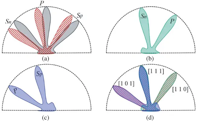
Figure 2. Three modes of propagation (a) initial beams (black) and scanning beams (red), (b) scanning beams (green) with an additional steering delay of T, (c) scanning beams (blue) with an additional steering delay of−T, (d) all three modes of propagation for determination of orientation.
primary beam “P”, secondary beam on the positive side “Sp”, and secondary beam on negative side “Sn”, respectively as shown in Figure 2(d). The beam steering-angle information and predefine anchor positions collectively estimate the orientation of the robot at the beginning. The accuracy of orientation depends on the beamwidth, narrower the beamwidth higher the accuracy.
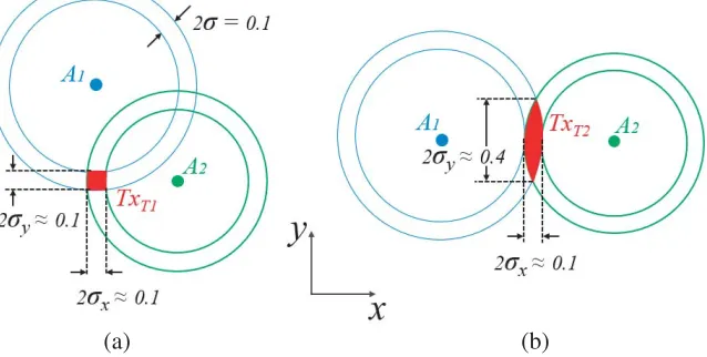
standard-deviations of thexandyaxis components, which is a function of the tag position with respect to the direction of the anchors for a given range measurement error σ as illustrated in Figure 3. The desired ranging beams to the anchors should be orthogonal as illustrated in Figure 3(a).
ΔRange = GDOP·ΔError (1)
GDOP =
σ2
x+σ2y
σ + 1 (2)
In Figure 3(a), the position of tag “TxT1” is measured by the range calculated by anchors “A1”
(a) (b)
Figure 3. Graphical illustration of the geometrical dilution of precision (GDOP). The annulus shows the standard deviation error bounds of the range corresponding to the anchors and the overlapped region in red shows the standard deviation of the expected area of the tag position. (a) GDOP = 1.73, (b) GDOP = 4.26.
and “A2”, which is in orthogonal (intersection angle 90◦) directions to the tag position thus giving best
GDOP. With the multiple beam system as illustrated in Figure 2, beams “Sn” and “Sp” are operating simultaneously to the anchors in orthogonal directions thus speeding up the positioning process with good GDOP. The flowchart diagram of the proposed approach is shown in Figure 4, which summarizes the complete process.
From the above discussions, it is clear that the proposed multi-beam high peak power IR-UWB transmitter array is pertinent for the application explained above. Nonetheless, the multi-beam IR-UWB transmitter array for the indoor positioning and tracking of moving objects in the densely cluttered environment has not been explored considerably. The proposed work utilizes an energy-efficient, high voltage IR-UWB pulse generator and implements electronically steerable multi-beam IR-UWB transmitter arrays, which significantly minimizes the technology-gap for the aforementioned application.
3. IR-UWB BEAMFORMING
The transient approach is preferred for the impulse radio ultra-wideband beamforming study and beam pattern analysis [50, 51]. The basic principle of the time-domain beamforming is to delay the IR-UWB pulses with finite time, which spatially superimpose each other in the aligned direction. The mechanism of the beamforming is illustrated in Figure 5. The steering angle of the beam depends on the steering time delay between the IR-UWB pulses and the separation between the transmitting elements. The steering angle of the beam “θ0” is defined in Eq. (3) for a linear array, where ΔT represents the relative
steering delay time between transmitting pulses; “d” is the separation of antennas; and “c” is the velocity of the electromagnetic wave [33].
θ0= sin−1
ΔT c d
(3)
The realization of the delay elements using RF phase shifter is common [33, 35]. However, the phase shifter is inherently narrowband, and designing an UWB phase shifter is practically
problematic [32]. Therefore, tunable true-time delay cell based beamformer would be the right choice for IR-UWB beamforming [32–37]. A block diagram of the proposed electronically controlled beamforming transmitter array is shown in Figure 5. The digital data pulse is first fed to tunable delay cells (Block D in Figure 5), which provides a finite time delay (steering delay) to the data pulses. The IR-UWB pulse generator (Block PG in Figure 5) uses the falling edge of delayed data pulses and generates corresponding delayed IR-UWB pulses [22]. The delayed IR-UWB pulses are transmitted through equally spaced antennas, which superimpose spatially to form a focused IR-UWB beam in the steered direction. The improvement in the directional peak power level of the beamforming transmitter array is expected to increase by 20 log10(N) = 12 dB for N = 4 [33, 35].
3.1. Simulations and Analysis
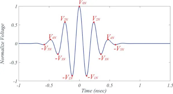
A linear transmitter array with four (N = 4) equally spaced isotropic radiating elements is realized in MATLAB for time-domain beamforming analysis. The time-limited Gaussian-envelope multicycle IR-UWB pulse in Eq. (4) is used to approximate the generated pulse as reported in [22]. The pulse given in Eq. (4) is plotted in Figure 6, indicating each crest and trough. The peaks (crests and trough) of the time-limited IR-UWB pulse (shown in Figure 6) are Gaussian-modulated. The resultant received signal in the far-field at any arbitrary angle of observation is given in Eq. (5) for N number of transmitting elements, whereAG(θ) is the angular gain of the transmitting antenna [52]. Since the spatial interference of IR-UWB pulses at some observation angleθmay produce dominant positive peak values and another angle it may produce dominant negative peak values. Hence, the peak-to-peak amplitude has been chosen for the radiation pattern plot to eliminate the ambiguity as shown in Eq. (6) [32].
x(t) = 1 σ√2πe
−t2 2σ2
(cos 2πf t) (4)
y(θ, t) = AG(θ) N
i=1
x
t−(i−1)d
c(sinθ0−sinθ)
(5)
BP(θ, t) = |yP-P(θ, t)|
|yP-P(θ, t)|max
(6)
In the case of monocycle IR-UWB pulse, there would not be any grating radiation beams even if the separation between the transmitting elements exceeds one wavelength “λ” [52]. However, the spatial summation of the multi-cycle IR-UWB pulse may produce multiple additional lobes if the separation (d in Figure 5) is larger than a wavelength. This condition is intentionally achieved in the proposed beamforming transmitter array in order to form multiple beams. The number of transmitting beams
will be equal to (2K+ 1), whereK is the integer part ofd/λ. The steering angle of the multiple beams can be evaluated using Eq. (7) for m = 0,±1,±2, ...,±K [53]. It is important to note [from Eq. (7)] that the number of transmitting beams depends on the separation (d); however, the steering of beams depends on ΔT.
θm = sin−1
ΔT c d −m
c f d
; −90◦ ≤θm ≤+90◦ (7) In a practical realization, the maximum possible relative steering time delay (ΔT) and delay resolution are fixed by the digitally tunable delay cell D in Figure 5. Assuming that the maximum possible relative steering time delay is ±600 ps for the maximum steering angle of ±90◦, the separation between the transmitting antenna elements is 18 cm using Eq. (3). Hence, an array with four transmitting elements (N = 4) with the separation 18 cm is taken for the study. The number of transmitting beams in this case for a center frequency of f ≈4 GHz (λ≈7.5 cm) will be 2K+ 1 = 5. The peaks of each cycle in the Gaussian-envelope IR-UWB pulse are not equal as shown in Figure 6. Therefore, the time-domain summation of four IR-UWB pulses, relatively partially delayed by one carrier cycle (at first grating beam) will produce peak-to-peak amplitude that is smaller than the summation with no relative spatial delay (at main beam). Similarly, the resultant peak-to-peak value for the Gaussian-envelope pulse (Figure 6) at the second grating beam (relatively spatially delayed by two carrier cycles) will be smaller enough than the main beam to be neglected. Hence, the four transmitting elements separated by 18 cm will be approximated to produce three dominant beams, appearing at 0◦ and±23.5◦ for no relative steering delays (ΔT = 0), calculated by Eq. (7) form= 0,±1 andf ≈4 GHz. The intensity along all the transmitted beams is calculated and explained in Subsection 3.2 with great details.
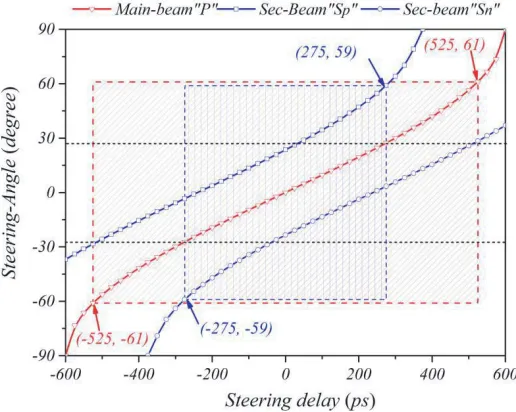
The steering-angle analysis of the array of four transmitting elements with 18 cm separation is performed for better utilization of steering delay range and scanning angle range. The variation of steering angle with the variation of steering delay (ΔT) between the transmitting IR-UWB pulses is plotted for the array spacing with 18 cm in Figure 7. It can be seen that one beam transmitter array needs ±525 ps steering delay difference to scan the area ranging from −61◦ to +61◦ (red line plot in Figure 7) without significant change in beamwidth. It can scan up to ±90◦, which requires ±600 ps relative steering delay. However, the beamwidth becomes significantly wider at higher angles. It can also be noted from Figure 7 that almost equal area (−59◦ to +59◦) can be scanned with three beams transmitter array without significant change in beamwidth, which needs only ±275 ps steering delay range. The reduction in steering delay tuning range improves the refresh rate of the system. In addition
to this, the area between±27◦will be scanned twice, which makes the system more reliable. However, an indoor positioning system with better GDOP requires the IR-UWB beams spatially apart, and ideally, it should be at orthogonal direction as explained in Section 2 [39, 40].
Therefore, in order to improve the GDOP, another transmitter array is optimized. The required separation between the transmitting elements of an array with 4-elements is calculated as 10.2 cm using Eqs. (3) and (7), which can produce three beams at 0◦ and±45◦for no relative steering delay (ΔT = 0). The normalized radiation patterns [using Eq. (6)] of the array with 18 cm separation (blue) and array with separation 10.2 cm (red) are plotted in Figure 8. It is evident that the array with separation 10.2 cm has beams at 0◦ and±45◦ which will eventually improve the GDOP.
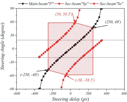
Similar to the array with spacing 18 cm, the steering-angle analysis for the array with 10.2 cm spacing is performed. The steering angle variations with relative steering delay (ΔT) are plotted in Figure 9. Results indicate that±250 ps is required to cover the area between±58.5◦ without significant change in beamwidth. Additionally, it scans the area between ±20◦ thrice and the rest of the area twice, which makes the system more reliable. However, for a fast processing system, the array can tune the steering delay variation from 50 ps to−250 ps or−50 ps to 250 ps to cover the area between±58.5◦;
Figure 8. The simulated normalized radiation pattern of the arrays with spacing 18 cm (Blue) and 10.2 cm (Red).
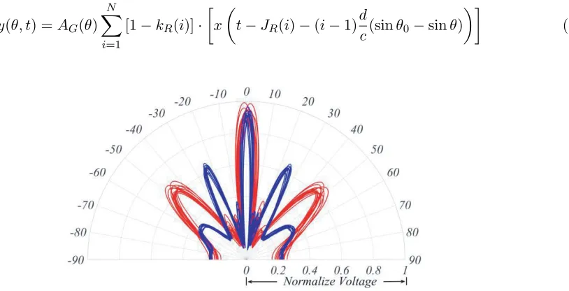
however, the covered area will be scanned by only one of the three beams in the specified regions. It will make the scanning less reliable but eventually speed up the processing time. This is required for the applications with a high refresh rate, where self-localization of moving objects is needed. Furthermore, it consists of two orthogonal beams and does not have any minor lobes as compared to an array with d= 18 cm, shown in Figure 8. However, the beamwidth increases as compared to an array with 18 cm spacing. Therefore, one has to take the trade-off according to the specific application scenario. In this paper, both arrays have been realized, and measurement results are presented. The measurement noise is added in the simulation to see the change in the radiation pattern of the proposed array. The received pulse at the receiver in the far-field incorporated with the measurement noise (variation in the steering delay and the amplitude of IR-UWB pulse) is given in Eq. (8). A random jitter “JR(i)” of ±25 ps in the steering delay and random variation of amplitude “kR(i)” of IR-UWB pulse by 10% is incorporated into the simulation as measurement noise. The normalized beam-patterns with the above-mentioned random noise are plotted in Figure 10.
y(θ, t) =AG(θ)
N
i=1
[1−kR(i)]·
x
t−JR(i)−(i−1)d
c(sinθ0−sinθ)
(8)
Figure 10. Normalized radiation pattern of the proposed array with a random noise range of 0< kR(i)<0.1 and−25 ps< JR(i)<+25 ps.
3.2. Radiation Intensity Calculation
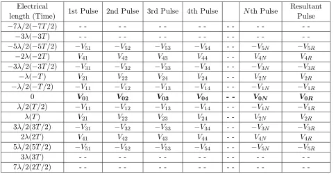
In this section, an intensity table is proposed to calculate the radiation intensity and the number of cycles of the radiated multi-cycle IR-UWB pulse along the transmitting beams. The intensity table of the N elements Gaussian-modulated transmitter array along the main transmitting beam is shown in Table 1. The first column of Table 1 indicates the time and corresponding electrical lengths. The pulse generated by each transmitting element (Block PG in Figure 5) is converted into the peak’s values corresponding to each electrical length indicated in column 1 of Table 1 (as indicated in Figure 6). Similarly, the N number of pulses is represented by the consecutive columns of Table 1. The last column represents the resultant received pulse in the far field, which is the summation of all peak values in a row corresponding to each electrical length indicated in column 1 of Table 1. In the direction of the main transmitting beam, there will be no relative spatial delay between the transmitted pulses. Therefore, all the pulses shown in Table 1 are aligned with time. The resultant pulse in the last column is the summation of all the aligned pulses. The amplitude of the resultant received pulse will beN-time of the individual transmitted pulse; however, the number of cycles of the resultant received pulse along the main beam will be the same as the pulse transmitted by individual pulse generators as shown in Table 1.
Table 1. Intensity table for the radiation along the main beam of transmitter array withN transmitting elements.
Electrical
length (Time) 1st Pulse 2nd Pulse 3rd Pulse 4th Pulse Nth Pulse
Resultant Pulse
−7λ/2(−7T /2) - - -
-−3λ(−3T) - - -
-−5λ/2(−5T /2) −V51 −V52 −V53 −V54 - - −V5N −V5R
−2λ(−2T) V41 V42 V43 V44 - - V4N V4R
−3λ/2(−3T /2) −V31 −V32 −V33 −V34 - - −V3N −V3R
−λ(−T) V21 V22 V24 V24 - - V2N V2R
−λ/2(−T /2) −V11 −V12 −V13 −V14 - - −V1N −V1R
0 V01 V02 V03 V04 - - V0N V0R
λ/2(T /2) −V11 −V12 −V13 −V14 - - −V1N −V1R
λ(T) V21 V22 V23 V24 - - V2N V2R
3λ/2(3T /2) −V31 −V32 −V33 −V34 - - −V3N −V3R
2λ(2T) V41 V42 V43 V44 - - V4N V4R
5λ/2(5T /2) −V51 −V52 −V53 −V54 - - −V5N −V5R
3λ(3T) - - -
-7λ/2(2T /2) - - -
-Table 2. Intensity table for the radiation along the first grating beam of the array with four transmitting elements.
1st Pulse 2nd Pulse 3rd Pulse 4th Pulse Resultant Pulse
−7λ/2(−7T /2) - - -
-−3λ(−3T) - - -
-−5λ/2(−5T /2) −V51 - - - −V8R
−2λ(−2T) V41 - - - V7R
−3λ/2(−3T /2) −V31 −V52 - - - - −V6R
−λ(−T) V21 V42 - - - - V5R
−λ/2(−T /2) −V11 −V32 −V53 - - −V4R
0 V01 V22 V43 - - V3R
λ/2(T /2) −V11 −V12 −V33 −V54 −V2R
λ(T) V21 V02 V24 V44 V1R
3λ/2(3T /2) −V31 −V12 −V13 −V34 −V0R
2λ(2T) V41 V22 V03 V24 V1R
5λ/2(5T /2) −V51 −V32 −V13 −V14 −V2R
3λ(3T) - - V42 V23 V04 V3R
7λ/2(7T /2) - - −V52 −V33 −V14 −V4R
4λ(4T) - - - - V43 V24 V5R
9λ/2(9T /2) - - - - −V53 −V34 −V6R
5λ(5T) - - - V44 V7R
11λ/2(11T /2) - - - −V54 −V8R
6λ(6T) - - -
-Figure 11. The resultant received pulse along the first grating beam of Gaussian-modulated four-element beamformer as obtained in the last column of Table 2.
delay will be one carrier cycle T (T = 1/f). Therefore, all the pulses are shifted by a relative delay of T in Table 2. Similarly, the Sn beam (shown in Figure 8) can be obtained by shifting the column with a relative delay of −T. The received resultant pulse along the first grating beam (Sp beam as shown in Figure 8) is obtained by the summation of all peaks in a row corresponding to the time shown in column 1 of Table 2. Since the peak value of the cycle is Gaussian-modulated, the maximum peak-to-peak value will be smaller than the received pulse along the main beam as shown in Table 1. In addition, the number of cycles in the received pulse will increase. The simulated resultant received pulse along the first grating beam is shown in Figure 11. It is evident from Figure 11 that the peak-to-peak amplitude is less than the pulse transmitted along the main beam, and the pulse is broadened as compared to the transmitted pulse (Figure 6). However, the most important thing to notice here is that the pulse radiated at the first grating beam (Sp beam as shown in Figure 8) not only is time-broadened but also provides an offset to the peak time stamp by 3T/2 as shown in Table 2 and Figure 11. Similarly, it will cause −3T /2 offset shift for the first grating beam (Sn beam as shown in Figure 8). Hence, it is important to compensate the offset time stamp in the algorithm while calculating the positions of an autonomous robot after identifying the beams as explained in Section 2. The intensity table along higher order grating beam can also be calculated in a similar way, but the intensity along the higher-order grating beam will be smaller than the main beam for the IR-UWB pulse shown in Figure 6. Hence, the intensity along the higher-order grating beam is neglected.
3.3. Measurement Results
Figure 12. Proposed beam-steering sub-circuit realized using true-time delay element cells.
Figure 13. Schematic representation of the radiation pattern measurement setup.
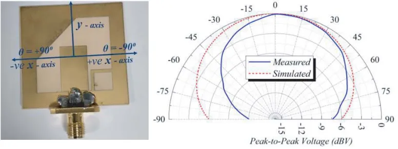
Figure 14. Patch antenna and the corresponding measured time-domain radiation pattern (solid blue) with the simulation radiation pattern (dotted red).
Figure 15. Complete measurement setup for the radiation pattern with the transmitting array and the receiving antenna connected to an oscilloscope.
(a) (b)
Figure 16. Normalized radiation patterns of the proposed transmitter array of 4-elements with spacing 18 cm. (a) No relative steering delay (ΔT = 0) and (b) ΔT =−50 ps.
Table 3. Comparison of IR-UWB beamforming with current state-of-the-art technology.
11 4 4 4 4
9 10 1 7 5 8
18 30 30 18 10 18
0 to 59 -60 to 60 -25 to 45 -45 to 90 -37 to 37
-60 (-90 ) to +60 (+90 )
References [32] [34] [33] [37] This work
Operating Frequency (GHz)
No. of channels
Delay range (ps)
Scanning Resolution (degree)
Antenna Spacing (cm)
Scanning range (degree)
3-10 0-6 3-5 3-10.5 3-5
0 to 500 ±880 -420 to 700 ±64 ±250 (±600)
0.4
10.2
o o o o o o o
o o o o o o o o o
o
o o
(a) (b)
(c) (d)
Figure 17. Normalized radiation patterns of the proposed transmitter array of 4-elements with spacing 10.2 cm. (a) No relative steering delay (ΔT = 0), (b) ΔT = −50 ps, (c) ΔT = +50 ps, and (d) ΔT = +250 ps.
d= 10.2 cm and ΔT = 0 eradicates the additional beams. In addition, two beams focus at orthogonal directions which will help to get better GDOP. The steered radiation pattern corresponding to the relative steering delay ΔT = −50 ps, ΔT = +50 ps, and ΔT = +250 ps are shown in Figures 17(b), (c), and (d), respectively. The radiation pattern in Figure 17(d) is similar to Figure 2(b), which can be used to determine the orientation of an autonomous robot as explained in Section 2. The observed differences between measured and simulated radiation patterns [Figures 16 and 17] are attributed to the antenna element radiation pattern. The radiation pattern of a single antenna element in the simulation compared with the measured time-domain radiation pattern of the opted antenna element is shown in Figure 14.
A comparison table of the proposed transmitter array with state-of-the-art technology is shown in Table 3. It can be seen from Table 3 that the proposed design is able to scan the area ranging from
−60◦ to +60◦without significant change in beamwidth, which only requires±250 ps. More significantly, multiple beams are formed which will speed up the localization refresh rate and help to achieve precise indoor positing of the autonomous robots.
4. CONCLUSION
the case explained in the paper. The optimized arrays are tuned to different steering angles, and time-domain radiation patterns are plotted. The comparison between the simulated and measured radiation patterns is provided, which shows a great match. The true-time digital delay cell is exploited, and the steering range from −60◦ (−90◦ to +60◦ (+90◦ with a scanning resolution of 5◦ and 8◦ is achieved and demonstrated.
The future work may include the development of an algorithm for indoor positioning and tracking. The algorithm will utilize the beam steering-angle analysis discussed in the paper to efficiently identify beams and consequently calculate the high accuracy positions of the tag. In addition, future work may also include the implementation of the overall system for indoor positioning and tracking of an autonomous tag moving in the cluttered environment.
ACKNOWLEDGMENT
The authors would like to acknowledge the support of ST Engineering in this work. This research was partially supported by the ST Engineering — NTU Corporate Lab through the NRF Corporate Laboratory@University scheme (Project Reference C-RP10B).
REFERENCES
1. Zhang, J. Z. J., P. V. Orlik, Z. Sahinoglu, A. F. Molisch, and P. Kinney, “UWB systems for wireless sensor networks,” Proc. IEEE, Vol. 97, No. 2, 313–331, 2009.
2. Siwiak, K. and D. McKeown, Ultra-wideband Radio Technology, John Wiley & Sons, Ltd, 2004. 3. Xu, Z., M. Luo, Z. Chen, H. Nie, and L. Yu, “Performance analysis of pulse generators for
UWB-based sensor networks,”International Conference on Communications and Mobile Computing, 466– 470, 2009.
4. Eryildirim, A. and M. B. Guldogan, “A Bernoulli filter for extended target tracking using random matrices in a UWB sensor network,” IEEE Sens. J., Vol. 16, No. 11, 4362–4373, 2016.
5. Norimatsu, T., et al., “A UWB-IR transmitter with digitally controlled pulse generator,” IEEE J. Solid-State Circuits, Vol. 42, No. 6, 1300–1309, 2007.
6. F. C. Commission, “Revision of Part 15 of the Commission’s rules regarding ultra-wideband transmission systems,” Washington, D.C. 20554, 2002.
7. Fontana, R. J. and E. A. Richley, “Observations on low data rate, short pulse UWB systems,” IEEE International Conference on Ultra-Wideband, 334–338, 2007.
8. Krebesz, T. I., G. Kolumban, C. K. Tse, F. C. M. Lau, and H. Dong, “Use of UWB impulse radio technology in in-car communications: Power limits and optimization,”IEEE Trans. Veh. Technol., Vol. 66, No. 7, 6037–6049, 2017.
9. Farid, Z., R. Nordin, and M. Ismail, “Recent advances in wireless indoor localization techniques and system,” J. Comput. Networks Commun., Vol. 2013, No. 185138, 1–12, 2013.
10. Yassin, A., et al., “Recent advances in indoor localization: a survey on theoretical approaches and applications,” IEEE Commun. Surv. Tutorials, Vol. 19, No. 2, 1327–13476, 2017.
11. Xia, J. J., C. L. Law, K. S. Koh, Y. Zhou, and C. Fang, “A 3–5 GHz impulse radio UWB transceiver IC optimized for precision localization at longer ranges,” IEEE MTT-S International Microwave Symposium Digest, 169–172, 2010.
12. Mahbub, I., S. K. Islam, and A. Fathy, “Impulse radio ultra-wideband (IR-UWB) transmitter for low power low data rate biomedical sensor applications,” IEEE Topical Conference on Biomedical Wireless Technologies, Networks, and Sensing Systems, 88–90, 2016.
13. Chia, M. Y. W., S. W. Leong, C. K. Sim, and K. M. Chan, “Through-wall UWB radar operating within FCC’s mask for sensing heart beat and breathing rate,” 2nd European Radar Conference (EURAD), 283–286, 2005.
15. Schleicher, B., et al., “IR-UWB radar demonstrator for ultra-fine movement detection and vital-sign monitoring,”IEEE Trans. Microw. Theory Tech., Vol. 61, No. 5, 2076–2085, 2013.
16. Nikookar, H. and R. Prasad, Introduction to Ultra Wideband for Wireless Communications, Springer Science Business Media B.V., 2009.
17. Lampe, L. and K. Witrisal, “Challenges and recent advances in IR-UWB system design,” IEEE International Symposium on Circuits and Systems (ISCAS), 3288–3291, 2010.
18. Silva, B. and G. P. Hancke, “IR-UWB-based non-line-of-sight identification in harsh environments: Principles and challenges,” IEEE Trans. Ind. Informatics, Vol. 12, No. 3, 1188–1195, 2016. 19. Silva, B. J. and G. P. Hancke, “Practical challenges of IR-UWB based ranging in harsh industrial
environments,”IEEE International Conference on Industrial Informatics, 618–623, 2015.
20. Leucci, G., “Ground penetrating radar: The electromagnetic signal attenuation and maximum penetration depth,” Sch. Res. Exch., Vol. 2008, No. 926091, 1–7, 2008.
21. Eltaher, A. and T. Kaiser, “A novel approach based on UWB beamforming for indoor positioning in none-line-of-sight environments,” RadioTeCc, 1–5, 2005.
22. Ansari, M. A. H., M. Sharma, and C. L. Law, “High peak power UWB-RFID transmitter tag for long range applications,” 2017 Progress In Electromagnetics Research Symposium — Fall (PIERS — FALL), 2045–2050, Singapore, November 19–22, 2017.
23. Neirynck, D., M. O. Duinn, and C. Mcelroy, “Characterisation of the NLOS performance of an IEEE 802.15.4a receiver,” 12th Workshop on Navigation, Positioning and Communications, 1–4, 2015.
24. Staderini, E. M., “UWB radar in medicine,”IEEE AESS Systems Magazine, 13–18, 2002.
25. Law, C. L., et al., “An ultra-wideband localization system for concrete debris tracking,” Asia Pacific Microwave Conference, 265–268, 2009.
26. Chandrakasan, A. P., et al., “Low-power impulse UWB architectures and circuits,” Proc. IEEE, Vol. 97, No. 2, 332–352, 2009.
27. Xia, J., C. L. Law, Y. Zhou, and K. S. Koh, “3–5 GHz UWB impulse radio transmitter and receiver MMIC optimized for long range precision wireless sensor networks,”IEEE Trans. Microw. Theory Tech., Vol. 58, No. 12, 4040–4051, 2010.
28. Bourdel, S., et al., “A 9-pJ/pulse 1.42-Vpp OOK CMOS UWB pulse generator for the 3.1–10.6-GHz FCC band,”IEEE Trans. Microw. Theory Tech., Vol. 58, No. 1, 65–73, 2010.
29. Kang, J., S. Rao, P. Chiang, and A. Natarajan, “Design and optimization of area-constrained wirelessly powered CMOS UWB SoC for localization applications,” IEEE Trans. Microw. Theory Tech., Vol. 64, No. 4, 1042–1054, 2016.
30. Wang, K., B. Li, M. J. Zhao, and Z. H. Wu, “Low-power implantable CMOS bipolar Gaussian monocycle pulse generator,”Electron. Lett., Vol. 53, No. 3, 201–203, 2017.
31. Dupleich, D., et al., “Directional characterization of the 60 GHz indoor-office channel,”31th URSI General Assembly and Scientific Symposium, URSI GASS, 14–17, 2014.
32. Chia, M. Y. W., T. H. Lim, J. K. Yin, P. Y. Chee, S. W. Leong, and C. K. Sim, “Electronic beam-steering design for UWB phased array,” IEEE Trans. Microw. Theory Tech., Vol. 54, No. 6, 2431–2438, 2006.
33. Delay, V., Y. L. Wang, and C. H. Heng, “3–5 GHz 4-channel UWB beamforming transmitter with 1◦scanning resolution through calibrated vernier delay line in 0.13-µm CMOS,”IEEE J. Solid-State Circuits, Vol. 47, No. 12, 3145–3159, 2012.
34. Safarian, Z., T. S. Chu, and H. Hashemi, “A 0.13µm CMOS 4-channel UWB timed array transmitter chipset with sub-200 ps switches and all-digital timing circuitry,”IEEE Radio Frequency Integrated Circuits Symposium, 601–604, 2008.
35. Natarajan, A., A. Komijani, and A. Hajimiri, “A fully integrated 24-GHz phased-array transmitter in CMOS,”IEEE J. Solid-State Circuits, Vol. 40, No. 12, 2502–2513, 2005.
37. Lai, C., K. Tan, Y. Chen, and T.-S. Chu, “A UWB impulse-radio timed-array radar with time-shifted direct-sampling architecture in 0.18-µm CMOS,”IEEE Trans. Circuits Syst. I Regul. Pap., Vol. 61, No. 7, 2074–2087, 2014.
38. Janky, J. M., K. A. I. Sharp, M. V. McCusker, and M. Ulman, “Indoor navigation via multi-beam laser projection,” United States Patent (US 20140285631A1), 2014.
39. Sharp, I., K. Yu, and Y. J. Guo, “GDOP analysis for positioning system design,” IEEE Trans. Veh. Technol., Vol. 58, No. 7, 3371–3382, 2009.
40. Feng, G., C. Shen, C. Long, and F. Dong, “GDOP index in UWB indoor location system experiment,” IEEE Sensors, 1–4, 2015.
41. Niu, R. and P. K. Varshney, “Joint detection and localization in sensor networks based on local decisions,”Conf. Rec. — Asilomar Conf. Signals, Syst. Comput., No. 2, 525–529, 2006.
42. Ciuonzo, D. and P. Salvo Rossi, “Distributed detection of a non-cooperative target via generalized locally-optimum approaches,”Inf. Fusion, Vol. 36, 261–274, 2017.
43. Ciuonzo, D. and P. Salvo Rossi, “Quantizer design for generalized locally optimum detectors in wireless sensor networks,” IEEE Wirel. Commun. Lett., Vol. 7, No. 2, 162–165, 2018.
44. Gu, Y., A. Lo, S. Member, and I. Niemegeers, “Wireless personal networks,” Communications, Vol. 11, No. 1, 13–32, 2009.
45. Ciuonzo, D., “On time-reversal imaging by statistical testing,”IEEE Signal Process. Lett., Vol. 24, No. 7, 1024–1028, 2017.
46. “Indoor path loss,” Apllication note: Digi International, 2012, [online], available: http://ftp1.digi.com/support/images/XST-AN005a-IndoorPathLoss.pdf.
47. Ansari, M. A. H. and C. L. Law, “Beamforming UWB-IR transmitter for NLOS indoor positioning and tracking application,” IEEE MTT-S International Wireless Symposium (IWS), 1–4, 2018. 48. Oshiga, O., X. Chu, Y. Leung, and J. Ng, “Anchor selection for localization in large indoor venues,”
2018 IEEE/ACM 26th International Symposium on Quality of Service (IWQoS), 1–6, 2018. 49. Langley, R. B., “Dilution of precision,” GPS World, Vol. 5, No. 10, 52–68, 1999.
50. Liao, C., P. Hsu, and D. Chang, “Energy patterns of UWB antenna arrays with scan capability,” IEEE Trans. Antennas Propag., Vol. 59, No. 4, 1140–1147, 2011.
51. Hussain, M. G. M., “Principles of space-time array processing for ultrawide-band impulse radar and radio communications,” IEEE Trans. Veh. Technol., Vol. 51, No. 3, 393–403, 2002.
52. Ries, S. and T. Kaiser, “Ultra wideband impulse beamforming: It is a different world,” Signal Processing, Vol. 86, No. 9, 2198–2207, 2006.