DESIGN AND STRUCTURAL ANALYSIS OF DRIVE SHAFT BY USING
COMPOSITE MATERIALS
Ev nagababu1, inaganti saicharan2
1Assistant Professor, Dept. of Mechanical Engineering, Nova College of Engineering and Technology, Ibrahimpatnam
2M.Tech Student, , Dept. of Mechanical Engineering, Nova College of Engineering and Technology, Ibrahimpatnam
E mail [email protected], [email protected]2
A BSTRA CT
Substituting composite structures for conventional metallic structures has many advantages because of higher specific stiffness and strength of co mposite materials. Th is work deals with the replacement of conventional two piece shaft with a single piece composite shaft for an automotive application. The advanced composite materials such as Boron, Carbon, and Kevlar with suitable resins are widely used now a days for automotive and other industrial applications especially for rotor applications because of th eir high specific strength (strength/density) and high specific modulus (modu lus/density). Poly mer matrix co mposites were proposed for light weight shafts in drivelines for auto motive, industries. Present work is conducted to analyze the co mposite drive shaft model of Toyota Quails, which is used for four wheel rear drive passenger cars. Boron/Epo xy, Kevlar/Epo xy, A lu miniu m-Boron/Epo xy and Carbon-Kevlar/Epo xy drive shafts are analyzed taking into consideration of the dimensional proportionality. Finally, considering the Density, Maximu m Shear stress, Total Deformation fro m the analysis, Kevlar/Epo xy is acceptable to use instead of steel fo r the Toyota Qualis driveshaft.
1 DRIVE SHA FT
The term Drive shaft is used to refer to a shaft, which is used for the transfer of motion fro m one point to another. Whereas the shafts, which propel (push the object ahead) are referred to as the propeller shafts. Propellers are usually associated with ships and planes as they are propelled in water or air using a propeller fan. However the drive shaft of the automobile is also referred to as the propeller shaft because apart fro m transmitting the rotary motion fro m the front end to the rear end of the vehicle, these shafts also propel the vehicle forward. The shaft is the p rimary connection between the front and the rear end (engine and differential) wh ich performs both the jobs of transmitting the motion and propelling the front end. Thus, the terms Drive Shaft and Propeller Shafts are used interchangeably.
Fig 1Schematic arrangement of Drive shaft under body of an Automobile
shaft is one of the most important components, which is responsible for the actual movement of the vehicle once the motion is produced in the engine. The designing of such a critical co mponent is usually stringent, as any fracture in this part could lead to a catastrophic failure of the vehicle when it is in motion.
2 SPECIFICA TION OF PROBLEM Almost all auto mobiles (which correspond to design with rear wheel drive and front engine installation) use a drive shaft for the transmission of motion fro m the engine to the differential. An automotive propeller shaft, or drive shaft, transmits power fro m the engine to differential gears of a rear wheel-driving vehicle. The static torque transmission capability of the propeller shaft for passenger cars, and small truck and vans should be larger than 3500 Nm and the fundamental bending natural frequency should be higher than 8000rp m to avoid whirling vibration. The whirling of the propeller shaft, which is a resonance vibration, occurs when the rotational speed is equal to the fundamental natural bending frequency, which is inversely proportional to the square root of specific stiffness (E/ ).
When conventional materials such as Steel or Aluminiu m are used, the weight of the drive shaft assembly is considerably high, which has a certain role in increasing the overall weight of the vehicle. Also, due to the increased weight of the shaft there are mo re chances of whirling of the shaft. To avoid this in conventional drive shafts, which have a length exceed ing 1.2m, the shafts are made in two pieces. However, the two piece steel propeller shaft has a complex and heavy configuration because three universal joints and a centre support bearing in addition to a spline are required,which produces noise and vibrations that are transmitted to vehicle through the centre support bearing.But by using advanced composite materials, the weight of the drive shaft assembly can be tremendously reduced. This also allows the use of a single drive shaft (instead of a two piece drive shaft) for lengths exceeding 1.2m. Apart fro m being lightweight, the use of composites also ensures less noise and vibration. However, the co mposite propeller shaft requires reliable jo ining of the co mposite shaft to the steel or Aluminium yoke of a universal joint.
3 A IM A ND SCOPE OF THE W ORK The project aims to reduce the weight of the drive shaft assembly by using advanced composite materials. For this project work, the drive shaft of a Toyota Qualis was chosen. The modeling of the drive shaft assembly was done using CATIA V5R20. A shaft has to be modeled to meet the stringent design requirements for automobiles. A comparative study of five d ifferent materials was conducted to choose the best-suited material. Steel (SM45C) was chosen for reference and the rest of the four composites were analyzed. The analysis was carried out using ANSYS 14.5 Work Bench for the following materials
4 LITERA TURE SURVEY
. COM POSITES
briefly described the application possibilities of composites in the field of auto motive industry to manufacture co mposite elliptic springs, drive shafts and leaf spumes in Engineers guide to composite materials, A merican Society for metal, 1986. Beard more and Johnson discussed the potential for co mposites in structural automotive applications fro m a structural point of view. Pollard [8] studied the possibility of the poly mer Matrix co mposite usage in driveline applications. Faust et.al [10] described the considerable interest on the part of both the helicopter and automobile industries in the development of lightweight drive shafts. Procedure for finding the elastic moduli of anisotropic laminated co mposites is explained by Azzi .V.D and Tsai.S.W.
5 DESCRIPTION OF THE PROBLEM The fundamental natural bending frequency for passenger cars, small trucks, and vans of the propeller shaft should be higher than 6,500 rp m to avoid whirling vib ration and the torque transmission capability of the drive shaft should be larger than 3,500 Nm. The drive shaft outer diameter should not exceed 100 mm due to space limitations. The drive shaft of transmission system is to be designed optimally for following specified design requirements as shown in Table 3.1
Tab 1 Specifications of Drive shaft model of Toyota Qualis
6 M ODELING OF DRIVE SHA FT A SSEM BLY However, in reality the drive shaft is not a simp le hollow cy linder, but a co mplex assembly of a number of parts. This assembly of parts which makeup the drive shaft assembly was modeled using CATIA software. The drive shaft of Toyota Qualis was chosen for determining the dimensions. Using these dimensions, the entire assembly was created in CATIA V5R20. The important parts created in CATIA in this assembly are also shown
along with the whole drive shaft assembly in Figures 4
Fig 2 Drive Shaft Assembly in CAT IA
Fig 3 Sleeve-Yoke in shaft assembly
Thus the Toyota quails drive shaft assembly was created in CATIA software with the prescribed dimensions as shown in the above Figure
Fig 4 Drive Shaft Assembly in CAT IA
7 M A TERIA L PROPERTIES
T ab 3 Material Properties of Boron/Epoxy Composite
Density of Boron/Epoxy = 2249 kg/m3
T ab 4 Material Properties for Kevlar/Epoxy composite
Density of Kevlar/Epoxy = 1402 kg/m3
Tab 5 Material properties of Aluminium-Boron/Epoxy Composite:
Density of Aluminium-Boron/Epo xy =2100 kg/m3
Tab 6 Material properties of Carbon-Kevlar/Epoxy Composite
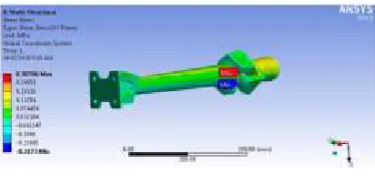
Thus, by using Ansys workbench, the model of drive shaft is imported into ansys and then it is applied with the material taken fro m the Engineering Data and then it is meshed as shown in the figure 5 The drive shaft model wh ich is meshed is then fixed at the end yoke and then the sleeve yoke subjected to a torque of 3500 N-m and then with the given parameters, the model is solved. By solving, required results such as maximu m shear stress, maximu m deformation Von-misses stresses and several other things can be attained
8 STA TIC AND MODAL ANALYSIS Thus, the model which is meshed is subjected to a torque of 3500 N-m is analysed for the four different composite materials and also for the steel(SM45C). The results of maximu m shear stress and deformations are shown below:
8.1 STATIC ANALYSIS RESULTS
8.1.1 STEEL(SM45C):
Fig 6 M aximum shear st ress of St eel
8.1.2BORON/EPOXY:
Fig 7 M aximum deformat ion of Boron -Ep oxy
Fig 8 M aximum shear st ress of Boron -Ep oxy
8.1.3 KEVLA R/EPOXY:
Fig 9 M aximum deformat ion of Kevlar/Ep oxy
Fig 10 Maximum SHEAR STRESS of Kevlar/Ep oxy
8.1.4 A L-BORON EPOXY COM POSITE
Fig 11 Total deformation of al-boron epoxy comp osit e
Fig 12 Shear st ress of al-boron ep oxy comp osit e
8.1.5 CA RBON-KEVLAR
Fig 13 T ot al deformat ion of carbon -kevlar
T able 7 Maximum Deformation, shear stress and Density of st eel and comp osit es
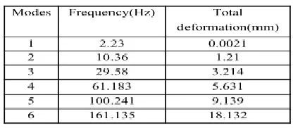
8.2 M ODAL ANALYSIS
Modal analysis is one of the structural analysis which g ives information about the vibrations created in the drive shaft model and also the corresponding maximu m deformations that it will undergo modal analysis helps to analyse a body when it is in motion.Modal analysis of Toyota quails drive shaft for the four composite materials along with steel can be done at six modes of frequencies and the corresponding deformations are take in to consideration and then the best suited material among these four composite materials has been declared.
T ab 8 M odal analy sis of st eel
T ab 9 M odal analy sis of Boron ep oxy
T ab 10 Modal analysis of Aluminum boron epoxy
T ab 11 Modal analysis of Carbon Kevlar epoxy
T ab 7 M odal analy sis of Kevlar Ep oxy
9 CONCLUSION
properties to act as the replacement for steel out of the considered four materials
10 REFERENCES
1. Agarwal B.D. and Broutman L.J.,1990, "Analysis and performance of fibreco mposites", John Wiley and Sons Inc.
2. [Thimmegowda rangaswamy, Sabapathy Vijayarangan,2005 Optimal sizing and stacking sequence of Co mposite Drive shafts,ISSN,vol-11,No.2.
3. Modelling and Analysis of Drive Shaft Assembly Using FEA by Raffi Mohammed, K. N.D. Malleswra Rao, Mohammad Khadeeruddin, vol.8, issue.2 (August 2013), e-ISSN:2278-067X, p-ISSN:2278-800X.
4. Jin Kook Kim.Dai GilLee, and Du rk Hyun Cho, 200, "Investigation of Adhesively Bonded Joints for Comoposite Propeller Shafts", Journal of Co mposite Materials, Vol.35, No., pp.999-1021.
5. Dai Gil Lee, et.al,2001, "Design and Manufacture of an Automative Hybrid Aluminiu m/Co mposite Drive Shaft, Journal of Co mposite structures, Vol.63,pp87-89.