A Compact Dual-Band Reconfigurable Open-End Slot Antenna
for Cognitive Radio Front End System
Santasri Koley* and Debjani Mitra
Abstract—A compact dual-band frequency reconfigurable microstrip-line fed open-end omnidirectional slot antenna is proposed in this paper suited for cognitive radio front end system. The antenna is capable of frequency switching at different frequency bands by changing the resonance length using two PIN diodes. The resonance frequency is tuned by a single varactor diode, placed at a certain location along the slot. The proposed antenna has a wide tuning range in the dual bands: 1.57 to 3.1 GHz and 3.8 to 5 GHz. The designed antenna has compact size of 40×40 mm2. An approximate transmission line model of the proposed antenna is derived to calculate the proper positioning of the diodes, and the design has been verified through numerical simulations and measured results.
1. INTRODUCTION
In modern era, the growth of wireless systems demands new frequency bands in the crowded spectrum. But the scarce spectrum is underutilized by current spectrum distribution system, where specific bands are assigned to particular services and only licensed users are assigned to licensed bands. Federal Communications Commission (FCC) had surveyed that 70% of the allocated licensed spectrum remains unused over the vast temporal and geographic locations [1]. Cognitive radio (CR) system has the capability to take the challenges of spectrum inefficiency by means of dynamic spectrum allocation [2]. Cognitive users search for unused frequency bands, called white spaces, and use them to communicate without any interference. So, in CR system, the communicating antenna must be tuned to the detected white space. Reconfigurable antennas have been realized in a variety of types including microstrip antenna [3], slot antenna [4], monopole [5], and dipole [6]. Antennas are usually tuned by introducing some switching techniques, such as electronic switches, photoconductive switches, FET switches, RF micro-electromechanical systems (MEMS), PIN diodes and varactor diodes.
A slot antenna [7–10] is attractive compared to other tunable antennas because of its wide tunability with varactor diodes or PIN diode switches across the slot and it is easier to fabricate as there no vias are required for biasing circuits. A simple compact reconfigurable slot antenna is presented in [7] with a very wide tuning range. In [8], a miniaturized tunable open end slot antenna is proposed. In [9], a slot antenna loaded with a series of PIN diode switches is realized and tuned by changing its effective electrical length of the slot. A frequency-reconfigurable microstrip slot antenna switches at six different frequency bands [10]. However, these types of slot antennas have been reported for single band tunability only.
Over the last few decades, the multiband antennas have become popular to overcome the challenges of modern wireless systems. Different multiband slot antennas are presented in [11–13]. In [11], a CPW-fed dual-band slot antenna is presented. But it can only be used for fixed dual-band operation. In [12], a dual-band slot antenna was studied that uses a single varactor to achieve tunability in only its second band of operation and has a fixed first band. On the other hand, in [13], both the bands of a dual-band slot antenna are tuned individually by using two varactor diodes placed at different position of the slot.
Received 17 May 2015, Accepted 9 June 2015, Scheduled 19 June 2015
* Corresponding author: Santasri Koley (santasrikoley27@gmail.com).
The antenna has similar radiation patterns at both bands with very small cross-polarization levels. It used two varactor diodes to achieve dual-band tunability. But the larger dimensions of these structures make it difficult to be used for cognitive radio front end systems.
In this paper, a dual band open-end slot antenna with wide tunability in both the bands is proposed with a single varactor diode. An open-end microstrip line is used to feed the slot antenna. The effective length of the slot is changed by activating PIN diode switches used at different position of the slot, which changes the resonant frequency position. Varactor diode is placed near the open end of the slot antenna for tuning purpose. An approximate transmission line model similar to [12] is implemented to calculate the proper positioning of the diodes mathematically. CST Microwave StudioTM is used for all subsequent design and optimization. The proposed antenna has an edge over some of the others [12, 13], that it can be realized with approximately one third compactness.
The paper is organization is as follows. In Section 2, describe the antenna design along with the principle of operation. Section 3 discusses the experimental results of the designed antenna. The paper is concluded in Section 4.
2. ANTENNA DESIGN PRINCIPLE
A slot antenna can be represented by a transmission line equivalent circuit [12]. The open-end slot antenna loaded with a varactor diode can be depicted through a transmission line model, as shown in Fig. 1. The capacitance value of the varactor diode increases the line capacitance at one point and thus, reduces the frequency of its first and all higher order resonances. This reduction is not uniform and depends on the location of the capacitor, its value, and the slot line impedance [13].
The resonance frequencies can be determined by applying the transverse resonance condition [14]
ZR+ZL= 0 (1)
where ZR and ZL are the input impedances to the right and left of the reference point, as shown in Fig. 1 and can simply be obtained from the following equations
ZR = jZostan(θ−θ1) 1−ωCZostan(θ−θ1)
(2)
ZL = −jZoscot(θ1) (3)
θ = β(ω)L, θ1 =β(ω)L1 (4)
Figure 1. Transmission line model of an open-end slot antenna loaded with a lumped capacitor.
whereβ is the slot line propagation constant,ωthe angular frequency,Cthe capacitance of the varactor diode,Zosthe line impedance of the slot,Lthe total length of the slot, andL1the position of the varactor
diode from the open side of the slot. Using (2) and (3) in (1), the resonance condition becomes
tan(θ−θ1)−cot(θ1) +ωCZostan(θ−θ1) cot(θ1) = 0 (5)
For a fixed value of varactor diode position L1 = 2 mm, this equation is solved for different slot
lengths and width of W = 1.2 mm. The propagation constant and impedance of the slot are calculated using equations provided in [15]. It is observed that the resonant frequency, largely dependent on the capacitor value, can be switched by changing the slot length as shown in Fig. 2.
The proposed antenna is designed on a 40×40 mm2low-cost FR4 substrate with thickness of 1.6 mm, dielectric constant of 4.4 and the loss tangent is 0.02. The proposed antenna has wide tunability with similar radiation pattern at both the bands. The simulated results are validated experimentally. An off-centered open-end microstrip line feed straight slot antenna is simulated on a FR4 substrate, as shown in Fig. 3(a). The slot line has a length of L = 65 mm and width of W = 1.5 mm on a ground plane with a size of 70×40 mm2. As the slot is open in one end, the impedance will be very high and on
the other end, impedance will be zero as the slot is closed. So the position of the 50 Ω feed line has to be optimized to match with the line impedance. Also, the length of the open circuited microstrip line can be tuned to compensate the reactive part of the input impedance for a good match. The simulation results are in close match to the numerical results obtained through (5) as depicted in Fig. 3(b). The slight mismatch of the two is because in the numerical results, there is no provision to consider the effects of the feed network parameters.
(a) (b)
Figure 3. (a) Topology of a straight open-end slot antenna loaded with variable capacitor, (b) numerical and simulation results.
3. EXPERIMENTAL RESULTS
The straight slot antenna structure has radiation pattern with maximum directivity at antenna’s broadside direction. However, in this structure, it is difficult to have similar radiation pattern with low level cross polarization at all the resonating bands over the entire tuning range. The problem has been addressed by bending the resonating slot which changes the electric field distribution across it. Authors in [12] have used a similar approach applied to design dual-band antenna.
(a) (b)
Figure 4. (a) Geometry of the proposed bent slot antenna, (b) fabrication prototype.
Figure 5. Typical capacitance of a Varactor diode SMV1231-079LF from Skyworks as a function of its bias voltage.
A microstrip line is used to feed the antenna where the lengths Lp = 11 mm and Lf = 9.7 mm are optimized to match the impedance of the slot. A varactor diode is placed at the open side of the slot and used to tune the resonating frequency by changing its capacitance value. By changing the bias voltage between 0 to 15 V, a capacitance variation of 2.35 to 0.466 pF is obtained from the used Varactor diode SMV1231-079LF from Skyworks (see Fig. 5). The varactor diode is simulated in CST Microwave Studio as aR-L-Cseries circuit with a package inductance ofL= 0.7 nH, series resistance of
R= 2.5 Ω, and capacitor C varying from 0.466 to 2.35 pF. Two RF PIN diodes (SMP1340-079LF) are used in the fabrication. 20 pF dc blocking capacitors GJM0336C1E200JB01D from Murata are used to isolate the dc biasing circuit.
As the slot impedance is dependent on frequency, matching the microstrip feed line to the slot impedance is very difficult. Its position is optimized to get the dual-band property. The simulated
(a) (b)
(c)
Figure 6. Simulated S11 results for different operating conditions, (a) both P1 and P2 ON state, (b)
P1 ON and P2 OFF state, (c) both P1 and P2 OFF state.
(a) (b)
(c)
Figure 7. Measured S11 results for different operating conditions, (a) both P1 and P2 ON state, (b)
E-plane H-plane
(a)
(b)
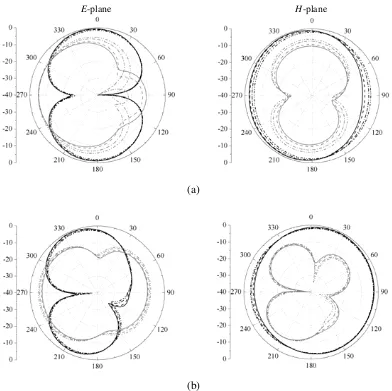
Figure 8. Simulated co-polarized (dark colored) and cross-polarized (light colored) radiation pattern when both P1 and P2 are in ON state, (a) first band, (b) second band. Solid line: C = 0.466 pF, Dash-dash: C = 0.59 pF, Dash dot: C= 1.09 pF, and Dash-dot-dot: C= 2.35 pF.
(a)
(b)
Figure 9. Simulated co-polarized (dark colored) and cross-polarized (light colored) radiation pattern when P1 is in ON state and P2 is in OFF state, (a) first band, (b) second band. Solid line: C = 0.466 pF, Dash-dash: C = 0.59 pF, Dash dot: C= 1.09 pF, and Dash-dot-dot: C= 2.35 pF.
E-plane H-plane
Figure 10. Simulated co-polarized (dark colored) and cross-polarized (light colored) radiation pattern when both P1 and P2 are in OFF state. Solid line: C= 0.466 pF, Dash-dash: C = 0.59 pF, Dash dot:
C= 1.09 pF, and Dash-dot-dot: C = 2.35 pF.
3.91 GHz to 4.21 GHz. When PIN diodes are in OFF state, total length of the slot become activated and the lowest frequency is achieved which is tuned from 1.59 GHz to 1.86 GHz. The return loss is measured by using a Vector Network Analyzer (VNA) as shown in Fig. 7. The simulated result shows good agreement with the measured one. Due to the current losses through the resistance of PIN diode, the measured return loss is less compares to simulated results.
E-plane H-plane
(a)
(b)
Figure 11. Measured (dark colored) and simulated (light colored) co-polarized radiation pattern, (a) 2.2 GHz, (b) 4.2 GHz.
Figure 12. Realized gain for the proposed sensing antenna.
4. CONCLUSION
This article discusses a planar microstrip feed low-cost dual-band open-end slot antenna providing similar radiation pattern and low cross-polarization at both the bands over whole tuning range. The proposed antenna uses a single varactor diode to tune both the bands and is noteworthy for the degree of compactness achieved (almost one third as compared to some of the related works). A transmission line equivalent circuit model has been used to design the antenna. Simulation results are seen to be in good agreement to the measurement results. Wide tuning range with compact size and omnidirectional radiation pattern makes it suited for cognitive radio front end system.
REFERENCES
1. “Spectrum policy task force report,” Fed. Commun. Commission, Washington, DC, Tech. Rep. 02-135, ET Docket, Nov. 2002.
2. Haykin, S., “Cognitive radio: Brain-empowered wireless communications,” IEEE Trans. on Commun., Vol. 23, No. 2, 201–220, Feb. 2005.
3. Zhu, S., D. Holtby, K. Ford, A. Tennant, and R. Langley, “Compact low frequency varactor loaded tunable SRR antenna,” IEEE Trans. on Antennas and Propagation, Vol. 61, No. 4, 2301–2304, Apr. 2013.
4. Saghati, A., M. Azarmanesh, and R. Zaker, “A novel switchable single and multifrequency triple-slot antenna for 2.4 GHz Bluetooth, 3.5 GHz WiMAX, and 5.8 GHz WLAN,” IEEE Antennas and Wireless Propagation Letters, Vol. 9, 534–537, 2010.
5. Tariq, A. and H. Shiraz, “Frequency-reconfigurable monopole antennas,”IEEE Trans. on Antennas and Propagation, Vol. 60, No. 1, 44–50, Jan. 2012.
6. Cai, Y., Y. Guo, and T. Bird, “A frequency reconfigurable printed Yagi-uda dipole antenna for cognitive radio applications,” IEEE Trans. on Antennas and Propagation, Vol. 60, No. 6, 2905– 2912, Jun. 2012.
7. Li, H., J. Xiong, Y. Yu, and S. He, “A simple compact reconfigurable slot antenna with a very wide tuning range,”IEEE Trans. on Antennas and Propagation, Vol. 58, No. 11, 3725–3728, Nov. 2010. 8. Wang, Y. and S. Chung, “A short open-end slot antenna with equivalent circuit analysis,” IEEE
Trans. on Antennas and Propagation, Vol. 58, No. 5, 1771–1775, May 2010.
9. Peroulis, D., K. Sarabandi, and L. Katehi, “Design of reconfigurable slot antennas,” IEEE Trans. on Antennas and Propagation, Vol. 53, No. 2, 645–654, Feb. 2005.
10. Majid, H., M. Kamal, A. Rahim, and M. Hamid, “A compact frequency-reconfigurable narrowband microstrip slot antenna,”IEEE Antennas and Wireless Propagation Letters, Vol. 11, 616–618, 2012. 11. Llorens, D., P. Otero, and C. Camacho-Penalosa, “Dual-band, single CPW port planar-slot
antenna,” IEEE Trans. on Antennas and Propagation, Vol. 51, No. 1, 137–139, Jan. 2003.
12. Behdad, N. and K. Sarabandi, “A varactor-tuned dual-band slot antenna,” IEEE Trans. on Antennas and Propagation, Vol. 54, No. 2, 401–408, Feb. 2006.
13. Behdad, N. and K. Sarabandi, “Dual-band reconfigurable antenna with a very wide tunability range,”IEEE Trans. on Antennas and Propagation, Vol. 54, No. 2, 409–416, Feb. 2006.
14. Pozar, D. M., Microwave Engineering, Wiley, New York, 2004.