Available Online atwww.ijcsmc.com
International Journal of Computer Science and Mobile Computing
A Monthly Journal of Computer Science and Information Technology
ISSN 2320–088X
IJCSMC, Vol. 4, Issue. 5, May 2015, pg.71 – 79
RESEARCH ARTICLE
A Novel Approach to Detect Black Hole and
Worm Hole Attacks in MANETs
Prof. Muhibur Rahman T.R.
1, Fayaz Ahamed P
2¹Department of Computer Science & Engineering, Ballari Institute of Technology & Management, Bellary-583 104, India ²Department of Computer Science & Engineering, Ballari Institute of Technology & Management, Bellary-583 104, India
1
[email protected]; 2 [email protected]
Abstract— Mobile Ad-hoc networks (MANET) are collections of self-organizing mobile nodes with dynamic topologies and have no fixed infrastructure. Because of their dynamic adhoc nature, in which unknown device develops spontaneous interactions between themselves, then networks are particularly vulnerable to various security threats. Therefore it is proposed to design and implement malicious node detection system to avoid black hole and worm hole attacks in MANETs. In this paper we use Cooperative bait detection scheme to detect black hole attacks. To detect Worm hole attack as well we incorporated Performance Evaluation Multipath Algorithm in CBDS scheme. Worm hole attacks are detected using hop-count and time delay analysis from the viewpoint of users without any special environment assumptions.
Keywords— CBDS, DSR (Dynamic Source Routing), Reverse Tracing, MANETs, Performance Evaluation Multipath algorithm, Adhoc
I. INTRODUCTION
Mobile Adhoc network is infrastructureless network that self-configured automatically by mobile nodes without the help of any centralized management. In MANET nodes have special characteristics that each node in MANET behaves like receiver and transmitter and allow communicating with other nodes in its radio range [1]. In order for a node to forward a packet to a node that is out of its radio range, the support of other nodes in the network is needed; this is known as multi-hop communication. Therefore each node must act as both a host and a router at the same time. The network topology normally changes due to the mobility of mobile nodes in the network. In MANET each node can communicate with the help of its neighbor node that’s comes in its radio range. Each node forward their packet to their neighbor node towards destination where path for transmitting message packet is suggested by routing protocol as shortest path [2]. Every routing protocol concentrates over shortest path where some malicious node over network use this greediness of routing protocol and present an illusion of shortest path between two end point of network and attack major traffic over the network [3].
When destination receives the RREQ, it can know each intermediary node’s address among the route. The destination node relies on the collected routing information among the packets in order to send a reply RREP message to the source node along with the whole routing information of the established route. DSR does not have any detection mechanism, but the source node can get all route information concerning the nodes on the route.
II. RELATED WORK
In [5], Liu et al. proposed a 2ACK scheme for the detection of routing
misbehaviour
in MANETs. In this scheme, two-hop acknowledgement packets are sent in the opposite direction of the routing path to indicate that the data packets have been successfully received. A parameter acknowledgment ratio, i.e., Rack, is also used to control the ratio of the received data packets for which the acknowledgment is required. This scheme belongs to the class of proactive schemes and, hence, produces additional routing overhead regardless of the existence of malicious nodes.In [6], Xue and Nahrstedt proposed a prevention mechanism called best-effort fault-tolerant routing (BFTR). Their BFTR scheme uses end-to-end acknowledgements to monitor the quality of the routing path (measured in terms of packet delivery ratio and delay) to be chosen by the destination node. If the behavior of the path deviates from a predefined behavior set for determining “good” routes, the source node uses a new route. One of the drawbacks of BFTR is that malicious nodes may still exist in the new chosen route, and this scheme is prone to repeated route discovery processes, which may lead to significant routing overhead.
In [7], Hongsong et al. proposes an intrusion detection model to combat the black hole attack in AODV routing protocol. In this model, a security agent, established by a hardware thread in network processor uses parallel multithreading architecture; try to detect two cases of figure of attack. Those exploiting AODV control messages RREQ (Route REQuest) and RREP (Route REPly). The agent monitors the RREQ-RREP messages at real-time and if any detection rule is violated, the black hole attack is detected and the malicious node is isolated and recorded to a black list. This solution requires a special material for its implementation. It is dedicated to AODV protocol and it considers only control messages, however that black hole attack can target data messages.
In [8], the concept of leashes is introduced to detect worm hole attacks. A leash is any information added to a packet in order to restrict the distance that the packet is allowed to travel. A leash is associated with each hop. Thus, each transmission of a packet requires a new leash. Two types of leashes are considered, namely geographical leashes and temporal leashes. A geographical leash is intended to limit the distance between the transmitter and the receiver of a packet. A temporal leash provides an upper bound on the lifetime of a packet. As a result, the packet can only travel a limited distance. A receiver of the packet can use these leashes to check if the packet has traveled farther than the leash allows and if so can drop the packet.
In [9], Mahajan et al. proposed some proposals to detect
worm hole
attacks like: 1) The abrupt decrease in the path lengths can be used as a possible symptom of theworm hole
attack. 2) With the available advertised path information, if the end-to-end path delay for a path cannot be explained by the sum of hop delays of the hops present on its advertised path, existence ofworm hole
can be suspected. 3) Some of the paths may not follow the advertised false link, yet they may use some nodes involved in theworm hole
attack. This will lead to an increase in hop delay due toworm hole
traffic and subsequently an increase in end-to-end delay on the path. An abrupt increase in the end-to-end delay and the hop queuing delay values that cannot be explained by the traffic supposedly flowing through these nodes can lead us to suspect the presence ofworm hole.
III.PROPOSED WORK
comprises four steps: 1) the initial bait step; 2) the initial reverse tracing step; 3) the shifted to reactive defence step, i.e., the DSR route discovery start process; 4) performance evaluation multipath phase.
A. Initial Bait Step
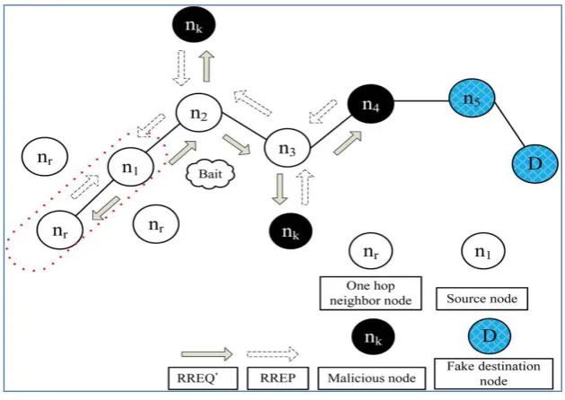
The aim of the bait phase is to attract a malicious node to send a reply RREP by sending the bait RREQ’ that it has used to advertise itself as having the shortest path to the node that detains the packets that were converted. The following method is designed to generate the destination address of the bait RREQ’. The source node selects an adjacent node, i.e., nr, within its one-hop neighbourhood nodes and cooperates with this node by
taking its address as the destination address of the bait RREQ’. The bait phase is activated whenever the bait RREQ’ is sent prior to seeking the initial routing path. The follow-up bait phase analysis procedures are as follows. First, if the nrnode had not launched a black hole attack, then after the source node had sent out the
RREQ’, there would be other nodes’ reply RREP in addition to that of the nrnode. Therefore, the reverse tracing
program in the next step would be initiated in order to detect this route. If only the nrnode had sent the reply
RREP, it means that there was no other malicious node present in the network and that the CBDS had initiated the DSR route discovery phase. Second, if nrwas the malicious node of the black hole attack, then after the
source node had sent the RREQ’, other nodes (in addition to the nrnode) would have also sent reply RREPs.
This would indicate that malicious nodes existed in the reply route. In this case, the reverse tracing program in the next step would be initiated to detect this route. If nrdeliberately gave no reply RREP, it would be directly
listed on the black hole list by the source node. If only the nrnode had sent a reply RREP, it would mean that
there was no other malicious node in the network, except the route that nrhad provided; in this case, the route
discovery phase of DSR will be started. The route that nr provides will not be listed in the choices provided to
the rout route discovery phase.
B. Initial Reverse Tracing Step
To detect the behaviours of malicious nodes, the reverse tracing program is used through the route reply to the RREQ’ message. The malicious node will reply with a false RREP if it has received the RREQ’. Then the reverse tracing operation will be conducted for nodes receiving the RREP, with the aim to deduce the dubious path information and the temporarily trusted zone in the route. It should be emphasized that the CBDS is able to detect more than one malicious node simultaneously when these nodes send reply RREPs.
Fig. 1 Black hole attack-node n4 drops all the data packets.
When a malicious node, for example, nm, replies with a false RREP, an address list P = {n1, . . . nk, . . . nm, . . . nr}
is recorded in the RREP. If node nkreceives the RREP, it will separate the P list by the destination address n1 of
the RREP in the IP field and get the address list Kk= {n1, . . . nk}, where Kkrepresents the route information from
source node n1 to destination node nk. Then, node nkwill determine the differences between the address list P = {n1, . . . nk, . . . nm, . . . nr} recorded in the RREP and Kk= {n1, . . . nk}. Consequently, we get K
K’k= P − Kk= {nk+1, . . . nm, . . . nr} (1)
Where K’krepresents the route information to the destinationnode (recorded after node nk). The operation result
of Kk’ is stored in the RREP’s “Reserved field” and then revertedto the source node, which would receive the
received K’kcan perform a forward back. Otherwise, nkshould just forwardback the K’k that was produced by
itself. In Fig. 2, although n4 can reply with K’4 = {n5, n6}, n3 willcheck and then remove K’4 when it receives the
RREP. After the source node obtains the intersection set of K’k, the dubious path information S replied by
malicious nodes could be detected,i.e.,
S = K’1∩ K’2∩ K’3. . . ∩ K’k. (2)
Given that a malicious node would reply the RREP to every RREQ, nodes that are present in a route before this action happened are assumed to be trusted. The set difference operation of P and S is conducted to acquire a temporarily trusted set T, i.e.,
T = P − S. (3)
To confirm that the malicious node is in set S, the source node would send the test packets to this route and would send the recheck message to the second node toward the last node in T. This requires that the node had entered a promiscuous mode in order to listen to which node the last node in T sent the packets to and fed the result back to the source node. The source node would then store the node in a black hole list and broadcast the alarm packets through the network to inform all other nodes to terminate their operation with this node. If the last node had dropped the packets instead of diverting them, the source node would store it in the black hole list. The situations faced by malicious nodes in the route are illustrated in Fig. 2.
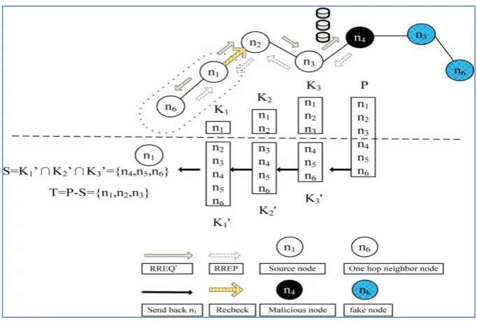
Fig. 2 Random selection of a cooperative bait address
In this case, a single malicious node n4 exist in the route, the source node n1 pretends to send a packet to the
destination node n6. After n1 sends the RREQ’, node n4 replies with a false RREP along with the address list P =
{n1, n2, n3, n4, n5, n6}. Here, node n5 is a random node filled in by n4. If n3 had receive the replied RREP by n4, it
would separate the P list by the destination address n1 of the RREP in the IP field and get the address list K3 =
{n1, n2, n3}. It would then conduct the set difference operation between the address lists P and K3 = {n1, n2, n3} to
acquire K’3 = P − K3 = {n4, n5, n6}, and would reply with the K’3 and RREP to the source node n1 according to
the routing information in P. Likewise, n2 and n1 would perform the same operation after receiving the RREP;
will obtain K’2 = {n3, n4, n5, n6} and K’1 = {n2, n3, n4, n5, n6}, respectively; and then will send them back to the
source node for intersection. The dubious path information of the malicious node, i.e., S =K’1∩ K’2∩ K’3 = {n4,
n5, n6}, is obtained. The source node then calculates P − S = T = {n1, n2, n3} to acquire a temporarily trusted set.
Finally, the source node will send the test packets to this path and the recheck message to n2, requesting it to enter the promiscuous mode and listening to n3. As the result of the listening phase, it could be found that n3 might divert the packets to the malicious node n4; hence, n2 would revert the listening result to the source node
Fig. 3 Reverse tracing program of the CBDS approach.
In Fig. 3, if there was a single malicious node n4 in the route, which responded with a false RREP and the
address list P = {n1, n2, n3, n5, n4, n6}, then this node would have deliberately selected a false node n5 in the
RREP address list to interfere with the follow-up operation of the source node. However, the source node would have to intersect the received K’kto obtain S = K’1∩ K’2∩K’3 = {n5, n4, n6}, T = P − S = {n1, n2, n3} and request
n2 to listen to the node that n3 might send the packets to. As the result of this listening phase, the packets that
should have been diverted to n5 by n3 should have been sent to n4. The source node would then store this node to
the black hole list. In Fig. 3, if n5 and n4 were cooperative malicious nodes, we would obtain T = P − S = {n1, n2,
n3}, and n2 would be requested to listen to which node n3 might send the packets. Either n5 or n4 would be
detected, and their cooperation stopped. Hence, the remaining nodes would be baited and detected.
C. Shifted to Reactive Defense Phase.
After the above (steps A and B), the DSR route discovery process is activated. When the route is established and if at the destination it is found that the packet delivery ratio significantly falls to the threshold, the detection scheme would be triggered again to detect for continuous maintenance and real-time reaction efficiency. The threshold is a varying value in the range [85%, 95%] that can be adjusted according to the current network efficiency. The initial threshold value is set to 90%. A dynamic threshold algorithm is designed that controls the time when the packet delivery ratio falls under the same threshold. If the descending time is shortened, it means that the malicious nodes are still present in the network. In that case, the threshold should be adjusted upward. Otherwise, the threshold will be lowered. It should be noticed that the CBDS offers the possibility to obtain the dubious path information of malicious nodes as well as that of trusted nodes; thereby, it can identify the trusted zone by simply looking at the malicious nodes reply to every RREP.
D. Performance Evaluation Multipath Phase.
IV.SIMULATIONRESULTS
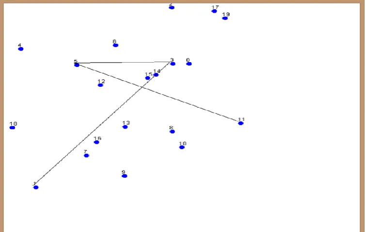
A simulation of above described CBDS is developed for identifying the black hole attack performed by the malicious node. Simulation is obtained using Java and Netbeans Technology. In these simulation scenario twenty nodes has been created. Each node has a communication range of 200.
Fig 4. Configuration of node
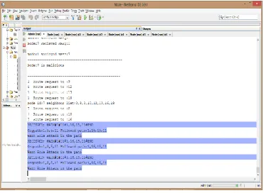
As shown different path from one to another node is calculated using DSR algorithm. Among the different path (1,3,5,11) has been chosen for our analysis. Consider node 0 as a source node and 11 as destination node. As source node 0 send data to the destination node 11, the intermediate nodes 5 and 3 forward the data to the destination node as shown in Fig 5. Consider Node 7 as malicious node, which performs the black hole attack. It advertises as having shortest path to the destination, as a result it receives the data from source node 0 and does not forward to the destination node 11. The original path before attack is 1,3,5,11. After the attack the path is 1,7.
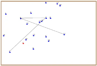
Fig. 7 Malicious Node (black hole) detected after attack using Reverse tracing program
Fig. 8 Node 0 identifies Node 7 as malicious node
Fig 9: Configuring Node 16 and Node 13 as Malicious nodes.
Fig. 10 Identifying Original path and malicious path
V. CONCLUSIONS
In this paper, a new mechanism (called the CBDS) is used for detecting malicious nodes in MANETs under gray/collaborative
black hole
attacks. To this mechanism, performance Evaluation Multipath Algorithmhas been added to detect the worm hole attack in MANETs. As future work, we intend to investigate the integration of the CBDS with other well-known message security schemes in order to construct a comprehensive secure routing framework to protect MANETs against miscreants. We also intend to use CBDS in other routing protocol like AODV.
REFERENCES
[1] B. Kannhavong, H. Nakayama, Y. Nemoto, N. Kato, and A. Jamalipour, “A survey of routing attacks in mobile ad hoc networks,” in IEEE Wireless Communications, Oct. 2007, pp. 85–91.
[3] Yang H., Luo H., Ye F., Lu S. and Zhang L.: Security in mobile ad hoc networks: challenges and solutions, In IEEE Wireless Communications, vol. 11, no. 1, pp.38–47 (2004).
[4] Yih-Chun Hu, Adrian Perrig, David B. Johnson, 2003 Packet Leashes: A Defense against Worm hole Attacks in Wireless Networks, Twenty-Second Annual Joint Conference of IEEE Computer and Communications, Volume 3, pp. 1976-1986.
[5] K. Liu, D. Pramod, K. Varshney, and K. Balakrishnan, “An Acknowl- edgement based approach for the detection of routing misbehavior in MANETs,” IEEE Trans. Mobile Comput., vol. 6, no. 5, pp. 536–550, May 2007.
[6] Y. Xue and K. Nahrstedt, “Providing fault-tolerant ad hoc routing service in adversarial environments,” Wireless Pers.Commun., vol. 29, pp. 367– 388, 2004.
[7] C. Hongsong, J. Zhenzhou, and H. Mingzeng, “A novel security agent scheme for aodv routing protocol based on thread state transition,” Asia Journal of Information Technology, vol. 5, no. 1, pp. 54–60, 2006. [8] Yih-Chun Hu, Adrian Perrig, David B. Johnson, 2003 Packet Leashes: A Defense against Worm hole
Attacks in Wireless Networks, Twenty-Second Annual Joint Conference of IEEE Computer and Communications, Volume 3, pp. 1976-1986.
[9] V. Mahajan, M. Natu, A. Sethi. ,Analysis of worm hole intrusion attacks in MANETS, IEEE Military Communications Conference (MILCOM), pp. 1-7, 2008.
[10] L. Lazos, R. Poovendram, C. Meadows, P. Syverson, L.W. Chang, Preventing Worm hole Attacks on Wireless Ad Hoc Networks: a Graph Theoretical Approach, IEEE Communication Society, WCNC 2005 [11] Jian-Ming Chang, Po-Chun Tsou, Isaac Woungang, Han-Chieh Chao, and Chin-Feng Lai, Member, IEEE. ,