Characterizing soil macroporosity by X-ray microfocus
computed tomography and quantification of the coring
damages.
J. Gallier1,a, F. Hubert1, J-C. Robinet1, P. Sardini1 and L. Caner1
1UMR HydrASA 6269, 40, Avenue du Recteur Pineau, 86022 Poitiers Cedex, France.
Abstract. X-ray Computed Tomography (X-ray µCT) was employed to characterize vertical variations of structural porosity of a soil profile (pore dimension higher than 5.103 µm3). Three distinct horizons of a Cambisol have been studied for a total depth of 75 cm: L, S1/S2 and S2/SFe horizons. Samples have been cored in situ by driving in PVC
tubes (inner diameter 10 cm). From reconstructed and filtered volumes, pores segmentation allows to study variations of structural porosity within the profile. Two kinds of porosity were identified: biological pores (tube-like) and physical pores (fracture-like). Structural porosity content varies strongly according to the horizons: from 5.48% in the L horizon to 6.48% in the S1/S2 horizon. The 3D connectivity of both
of these pore types was also assessed. During sampling, soil shearing induced damages around the cores. Identification and quantification of the damaged zone was performed from the calculation of porosity profile from core surface to core heart. In average, the damaged zone reaches a depth of 1 cm. Porosity loss (compaction) or porosity increase (fracturing) was observed according to the studied profile.
1 Introduction
Among other,characterization of soil porosity is important in order to study its transfer properties [1]. In soil science, two kinds of porosity are distinguished: textural porosity, due to the soil building components (minerals, organic matter…) and structural porosity which is linked to soil aggregation and external factors dependent (biological, mechanical, physical…) [1]. Structural porosity plays an important role in fluid transfers.
Two dimensional approaches on thin sections or consolidated blocks, combined to image processing, have been widely used to study the pore size distribution, pore shape, and pore connectivity [2, 3, 4, 5]. To reach the three-dimensional geometry of soil porosity, it is possible to use different techniques such as serial sectioning [6] or X-ray computed tomography (X-ray µCT).
Contrary to serial sectioning X-ray µ CT is a non-destructive imaging technique. X-ray µ CT technique is mainly used to characterize soil structural porosity [7, 8] and to study transfers in soil [9]. The aim of this work is to characterize the structural porosity of a soil profile using X-ray µCT and also to highlight the effect of sampling technique on the calculated porosities.
a
Email : [email protected]
2 Materials and methods
The studied soil profile is located in a long term ecological research site from INRA (Lusignan site, South West of France) that was set up in 2003. The soil is classified as a Cambisol (WRB, 2006) with polygenic origin [10]. Five horizons were defined in the field from surface to depth: L, S1, S2,
SFe, M. At the profile scale, this soil has high lateral heterogeneity caused by old degradation zones
(Figure 1, a). Clay fraction content increases with depth from 15 % in the L horizon to 42 % in the M horizon in depth. The clay minerals indentified in the soil are kaolinite, chlorite, illite and interstratified clays. Quartz, feldspar, micas and iron oxides and hydroxides are also present in this soil[11]. A small amount of organic matter is concentrated in the L horizon.
Fig. 1: a) A soil profile of the studied Cambisol. b) a guide was used to maintain vertically the PVC cores during sampling. c) Illustration of the method used to extract cores from the soil.
The soil samples were cored in December 2006 into PVC pipes having an inner diameter of 10 cm and 6 mm wall thickness. The bottom of the pipes was sharpened to get a better penetration into the soil. To drive the pipes straight during the coring, a specific guide was built (Figure 1, b). The guide is made from two plates of wood where their centers are pierced with a diameter of hole a bit larger than the PVC pipe. Those plates are set up one above the other with a distance dependant of the pipes height. Then, they are maintained together in the same position by four rods set in each corner of the plates and which are also driven into the soil. The backhoe of an excavator was used to drive the pipe in soil with only one try without shocking, to get undisturbed cores (Figure 1, c). The same tool was used to drive the core out the soil. To investigate the structural porosity of the three first horizons, a first pipe was knocked at 70 cm depth. However, to limit compaction effect observed in the surface horizon due to this deep sampling, a second pipe was knocked at only 45 cm. Just after sampling the bottom and the top of the sample are tightly closed with paraffin and kept at 4°C in order to avoid soil desiccation, and biological development.
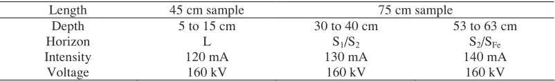
Table 1. Sample characteristics and µXRay- CT acquisition parameters
Length 45 cm sample 75 cm sample
Depth 5 to 15 cm 30 to 40 cm 53 to 63 cm
Horizon L S1/S2 S2/SFe
Intensity 120 mA 130 mA 140 mA
Voltage 160 kV 160 kV 160 kV
nut rod
wood plates
guide PVC pipe
Bachoe bucket
a)
b)
c)
drive in
pull up
L
S1
S2
SFe
M
55cm 60cm
80cm
120cm L
S1
S2
SFe
M
55cm 60cm
80cm
To select regions of interest, mosaics of X-ray radiographs have been built along the two soil columns. Three soil cores of 10 cm high were imaged using X-ray Computed Tomograph Viscom X8050 at the Centre de Tomography of Poitiers University (Table 1). Reconstructed volumes have a size of 1004 × 1004 × 1004 pixels and a voxel size of 100 µm. The images are grey level images and recorded in 8 bit format.
Images are trimmed in order to delete the PVC pipe to analyze only the soil. Beam hardening artifact, blur effect and black edge corners were corrected thanks to the reconstruction software DigiCT©. In order to reduce ring artifacts, which are due to CCD camera flowed pixels, a specific
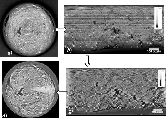
method of image processing has been developed. Each slice has been processed according to the following methodology (Figure 2):
- Transform the slice in polar coordinate image (image 1). The rings appear as horizontal variations in grey level. (Figure 2b)
- Fast Fourier Transform (FFT) of image 1 (image 2)
- Filtering of image 2 using Butterworth low-pass filter (image 3) - FFT-1 of image 3 (image 4) (Figure 2c)
- Return back to the cartesian image (Filtered image) (Figure 2d)
The final step of the pre-treatment concerns the segmentation of grey scale image to binary one. Thresholding by low and high boundaries was performed according to the two modes observed in grey level histogram. As structural porosity was investigated, pores having a volume higher than 50000 voxels (5.103 µm3) were specifically studied.
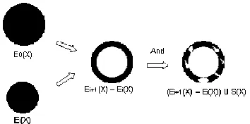
Finally, a last routine was developed to measure the variations of porosity near the core borders which were induced by soil sampling. Radial variation of the porosity was calculated on 3D concentric rings created from successive erosion of the complete core. As an example, if one supposed that the coring damages would be negligible, the calculated porosity has to be equivalent for each ring, whatever its distance to core border (Figure 3).
b) a)
c)
Fig. 2: The images representing the steps of the method use to reduce the ring artifacts. The contrast of the images is enhanced in order to visualize the reduction of the ring artefacts. Image a) is a slice of the reconstructed volume of the S1/S2 horizon with ring artifact. Image b) is the same image in polar coordinate.
Image c) is the image after the filtering using Butterworth low-pass filter. Image d) is the same image in Cartesian coordinate without ring artefact.
Fig. 3
:
To measure the radial variation of porosity, “E(X)” sets (which corresponds approximately to disks) where used. First these disks are combined together to create rings of different size. Second, in order to computethe porosity of each ring , the porosity image of the sample (S(X)) is superimposed to each ring.
3 Results and discussion
Three horizons of the Cambisol were studied: the L, the S1/S2 and the S2/SFe.
3.1 Radiographs
The radiographs observation shows two kinds of objects from millimeter to centimetrer scale: - dark object which correspond to oxides or detritic minerals. It is impossible to define those
minerals from radiographs.
- light object which correspond to structural porosity.
The objects which have a size lower than millimeter correspond to the clay matrix. The radiographs do not permit any analysis. Those images are only use to create the three dimensional samples.
3.2 Slices observation
Once images are filtered from ring artifacts, it is possible to analyze the three-dimensional distribution of porosity. However, note than some stars artifacts around oxides grains are still encountered. The resolution only permits the observation of structural porosity.
Contrary to radiographs, inside the reconstructed volume the porosity appears in low grey level (dark object) (Figures 4 c and d and Figure 5 a).
Before analyzing these samples, the coring effect is taken into account. The image processing method described in figure 3 showed that coring effect decreases from the edge to the centre of the core. The mean distance from the rim affected by coring, was about 10 mm (Figure 4), with a loss of –25% porosity for compaction processes, and with a gain of +25% for the fracturation. It is emphasized that sample shearing affects core macroporosity in two opposite ways. For the S1/S2
Fig. 4 : Diagrams showing the coring effects, the dashed line is the mean porosity. The a) diagram shows the compaction effect near the border of the core. It is illustrated by image c), slice of the S1/S2 horizon. The b)
diagram shows the increase of porosity. It is illustrated by the image d) slice of the L horizon.
Fig. 5
:
a) Slice of the S1/S2 horizon. The darker objects correspond to porosity and the lighter objects correspond to oxides. Ring artifacts are filtered, but star artifacts around oxides can be still detected b) Threedimensional image of structural porosity in the L horizon.
Image analysis of the reconstructed volumes shows two different pore morphologies within the samples. The first one presents tubes forming a tortuous network (Figures 5, a and b). The second one shows vertical cracks crosscutting the entire core (Figure 5, a and b). Then, based on these morphology criteria, it is possible to define two origins of the structural porosity (Figures 5, a and b): - biological (tube)
- physical (cracks)
2.0 3.0 4.0 5.0 6.0 7.0 8.0
0 10 20 30 40
ring thickness [mm]
S tr u ct u ra l p o ro si ty c o n te n t p er r in g ( % ) 2.0 3.0 4.0 5.0 6.0 7.0 8.0
0 10 20 30 40
ring thickness [mm]
S tr u ct u ra l p o ro si ty c o n te n t p er r in g ( % ) Compaction near the border of the core.
Cracks created by coring
c) d)
a) b)
biological porosity
physical porosities
tubular wormholes. Two kinds of wormhole seem to be present. The most representative are thin and straight tubular wormholes and a second one is a bigger wormhole in U-shape. Into this horizon, visually, the structural porosity decreases from the top to the bottom of the sample.
The structural porosity of S1/S2 horizon is mainly physical (vertical cracks). Those cracks present
some preferential orientation, in 3D they form planes which go continuously through the entire core thickness. The biological porosity is also represented by a wormhole which goes through the entire sample thickness.
Structural porosity is poorly observed inside the deeper horizon (S2/SFe). Thresholding permits to
quantify the structural porosity of the samples (table 2). The results show a significant increase of structural porosity from the L horizon to the S1/S2 horizon (5.48% to 6.48% respectively). The
structural porosity is negligible inside the S2/SFe horizon (around 0.29%, which is supposed to be
near the measurement error). Emphasis that even if the S2/SFe horizon has a low structural porosity at
the scale of the core, a structural porosity exists at the scale of the soil profile. Indeed, from field observations, cracks are evidenced in this depth, but crack spacing is clearly larger than the core diameter (crack spacing is estimated to be more than 10 cm).
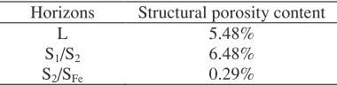
Table 2. Structural porosity was measured from the thresholding of the grey level histogram. The S2/SFe structural porosity content is negligible.
Horizons Structural porosity content
L 5.48%
S1/S2 6.48%
S2/SFe 0.29%
The structural porosity network is generally underscored by 3D pore connectivity: for the first two horizons, structural porosities is 3D connected. Moreover, biological and physical porosity are also connected between each other. Almost all the structural porosity is connected therefore these networks constitute preferential pathways for water. The soil does not show traces of hydromorphy, even if it is lowly permeable; this observation could be explained by the high connection of its structural porosity. Indeed this network permits water flow into the soil at least from the soil surface to the S1/S2 horizon.
4 Conclusion
References
1. P. Stengel. Utilisation de l’analyse des systèmes de porosité pour la caractérisation de l’état physique du sol in situ. Ann. Agron. 30, 27-51 (1979)
2. C. J. Moran, & A. B. McBratney. Acquisition and analysis of three-component digital images of soil pore structure. I. method. Journal of Soil Science, 43(3), 541-549. (1992).
3. A. J. Ringrose-Voase. Measurement of soil macropore geometry by image analysis of sections through impregnated soil. Plant and Soil, 183(1), 27-47. (1996).
4. P. Droogers, A. Stein, J. Bouma, & G. De Boer. Parameters for describing soil macroporosity derived from staining patterns. Geoderma, 83(3-4), 293-308. (1998).
5. P. Dudoignon, S. Caussèque, M. Bernard, V. Hallaire, and Y. Pons. Vertical porosity profile in a clay-rich marsh soil. Catena; 70 (3). 480 - 492. (2007)
6. E. Moreau, B. Velde, & F. Terribile. Comparison of 2D and 3D images of fractures in a vertisol. Geoderma, 92(1-2), 55-72. (1999)
7. H. J Vogel. Morphological determination of pore connectivity as a function of pore size using serial sections. European Journal of Soil Science, 48(3), 365-377. (1997)
8. G.S. Warner, J.L. Nieber, I.D. Moore, R.A. Geise. Characterizing macropores in soil by computed tomography. Soil Sci. Am. J. 53, 653-660 (1989).
9. J. Perret, S.O. Prasher, A. Kantzas, C. Langford. A two-domain approach using CAT scanning to model solute transport in soil. J. Environ. Qual. 29, 995-1010 (2000).
10. C. M.Girard, & D. Baize. Scales and ecosystems. Natures Sciences Societies, 4(4), 310-323. (1996)