ABSTRACT
DIAZ, FRANCISCO J. On the Analysis of the Printing Nip on Sheetfed Lithographic Presses and its Implications on the Runnability of Common Substrates. (Under the directives of Dr. Tarek Echekki).
This dissertation is based on the thesis that: Adequate analysis of the offset printing nip, under proper solutions of the Navier-Stokes equations —NSE— for the ink flow and, every day common sense, must provide answers to relevant questions still pending response in the offset printing process. Among these questions are: the influence of wall pressure on the flow, the presence or lack thereof of cavitation, the influence of the Newtonian and non-Newtonian conditions of the ink and, the validity of Stefan’s law in the flow as ink and substrate split from the blanket/ink interface.
As those questions are properly studied and, solutions are provided on the influence of the ink flow on common substrates (mainly focused on coated papers). Answers are presented on ink velocity profiles, influence of ink viscosity and ink layer height (under full ink coverage), and adequate release of the substrate at common SFO —Sheet Fed Offset— printing conditions.
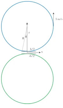
In order to understand the flow, a model is proposed by using a thin channel, high aspect ratio, based on the very thin ink layer running at 2 microns (2 x 10⁻⁶ m) through a long contacting channel S, of 0.012 m, while the walls move at a set velocity of 3 m/s and known contacting pressure (peaking at the center at 1 MPa).
The problem is divided in two regions with similar geometry (high aspect ratio) but, with different boundary conditions. Inside the nip, the problem is a Couette-like flow. Once it leaves the nip, the problem turns into an adhesion matter. Due the high aspect ratio, NSE can be simplified to the Lubrication Approximation Equations —LAE—.
well that: the fluid is incompressible, the interaction of the ink and substrate happen very rapidly and prevent any change in the ink viscosity, the temperature of the system is constant and heat transfer has no influence on the analysis. In addition, curvature is negligible and finally, wall pressure is known (through work developed here using Finite Element Methods). Since wall pressure is known, its derivative is also known and NSE can be solved swiftly by successive integration under the printing boundary conditions. Each of these assumptions is discussed in this dissertation and proven to be valid for the analysis of the flow in the offset printing nip.
As a result of the analysis, it is found that solutions for the NSE, under Newtonian and non-Newtonian (Power Law viscosity model), provide a very similar profile for the fluid’s velocity field. This is also true for the region of adhesion at nip’s exit. The analysis presented here supports the simplification of treating offset ink as a Newtonian fluid since the results for ink flow velocity are rather similar.
The influence of porosity at the bottom wall, treated as a boundary conditions for the solution of the flow, proves to be very minimal. Similarity simplifications such as Berman-Blassius are not instrumental in the analysis of the printing nip, since the result is completely impervious to porosity. The solution through LAE provide adequate and reasonable soltions to the ink flow. LAE serve at nip’s exit, under adhesion solutions in cylindrical coordinates (offered by other researchers) and, in rectangular coordinates developed in this dissertation under the Reynolds adhesion equation to find answers for ink internal pressure and extemsion.
On the Analysis of the Printing Nip on Sheetfed Lithographic Presses and its Implications on the Runnability of Common Substrates
by Francisco J. Díaz
A dissertation to the Graduate Faculty of North Carolina State University
in partial fulfillment of the requirements for the Degree of
Doctor of Philosophy
Mechanical Engineering
Raleigh, North Carolina
2013
APPROVED BY:
––––––––––––––––– ––––––––––––––––– Dr. Tarek Echekki Dr. Robert T. Nagel Committee Chair
BIOGRAPHY
ACKNOWLEDGEMENTS
First, I want to thank the Lord Jesus for his love, care and support throughout my whole life. My family has shown incredible patience and understanding, encouraging every part of the way to get this work through. My wife Maria Teresa, my sons Pablo and Santiago who have pushed me and showed me that the work was possible.
I want to thank my late father and elderly mother who, through the years, made me believe that being an engineer was relevant and possible.
Dr. Tarek Echekki has been more than an advisor in this work. He took the task of bringing this research back to its place, once the author under a series of tough difficulties had almost abandoned it. He has made me think like a researcher and has challenged me to make the discussion more meaningful. In so, improving not only this work but, the more comprehensive scope of my work as an engineer.
Dr. Nagel provided encouragement and support, understanding the challenges of part-time student, full-part-time worker. He opened the door for me to start this adventure and has helped me to see it through. Dr. NGaile encouraged me with the use of Finite Element Methods, by doing that he helped me achieve one of my goals in coming back to school. Dr. Pawlak, over several years now, has helped me understand the difficulties and importance of the paper substrate; he has always opened opportunities for me to present work and get involved in the field. I value not only the advise but, the friendship of all of this advising committee.
TABLE OF CONTENTS
LIST OF TABLES . . . viii
LIST OF FIGURES. . . ix
Chapter 1. Introduction and literature review . . . 1
1.1 Objective for chapter 1. . . 2
1.1.1 Scope. . . 3
1.2 Sheetfed offset printing process — SFO—. . . 3
1.3 Substrate’s Runnability definition. . . 5
1.4 Framework and literature review. . . . 7
1.4.1 Ink tack, ink flow and substrate physics. . . . 8
1.4.2 Mechanical properties. . . . 10
1.5 Solutions for flow in a porous channel. . . .13
1.6 Stefan’s Law and ink tack in the printing nip . . . 14
1.7 Ink tack definition. . . 15
1.8 Offset inks. . . 18
1.9 Cavitation. . . 19
1.10 Ink and Heat Transfer. . . 23
1.11 Walker- Fetsko and ink immobilization. . . 24
1.12 Paper absorption. . . 25
1.13 Other Factors. . . 26
1.14 Blanket and paper elasticity. . . 27
1.15 Printability. . . 28
1.16. Other relevant work . . . 29
1.17 Adhesion and other NSE solutions . . . 34
Summary. . . 35
2.1 Objectives for Chapter 2. . . 36
2.2 Validation of assumptions. . . 36
2.2.1 2-D versus 3-D problem . . . 37
2.2.2 Constant temperature and heat flow. . . 38
2.2.3. NSE represent the problem. . . 38
2.2.4 Flow is steady, incompressible and the entrance region is very small . . . 39
2.2.5 The wall pressure p(x) is known. . . 40
2.2.5.1 Contact pressure and the shape of contact function p(x).. . . 42
2.2.5.2 Effect of p(x) on NSE . . . 44
2.2.6 Substrate porosity . . . 45
2.2.7. The flow geometry can be modeled by a thin channel and curvature is negligible. . . 46
2.2.8 Ink tack rise is not relevant in the problem . . . 48
2.3 Application and comparison between similarity transformation and LAE solutions to NSE for the thin porous channel in SFO. . . 50
2.3.1 Berman-Blassius similarity analysis with one bottom porous wall. . . 50
2.3.2 Application of Berman-Blassius to the printing porous channel. . . 52
2.4 Consideration on absorption velocity v0. . . 54
2.5 First approach to the problem by the Lubrication Approximation—LAE. . . 58
2.5.1 LAE under boundary conditions governed by velocity at the entrance u0. . . . 58
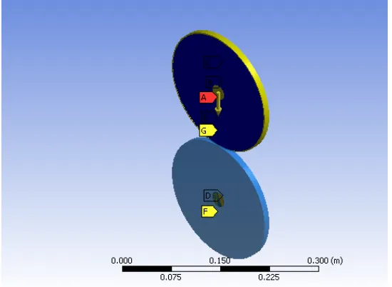
2.5.2 Modeling velocity driven flow under Ansys™. . . 60
2.5.3 Solving LAE for one single dot for pressure peaking at the middle. . . 61
Summary. . . 62
Chapter 3. Questions and the flow inside the nip. . . . . . 64
3.1 Pending questions. . . 64
3.2 Lubrication Approximation Equations —LAE—. . . 65
3.2.2 Newtonian Case — h, curvature varies as blanket/paper interact. . . 70
3.2.3 Non-Newtonian solution under the Power Law viscosity model. . . 72
3.2.4. LAE for a non-Newtonian fluid under Power Law model. . . 74
3.3 Analysis of viscosity under Power Law model. . . 75
3.4 Comparison between Newtonian and non-Newtonian solutions. . . 76
3.5. Non-Newtonian case for Power Law fluid with Porosity at bottom wall. . . 77
Summary. . . 81
Chapter 4. Flow at nip’s exit. . . 82
4.1 LAE at nip’s exit. . . 82
4.2. Flow model for a Power Law fluid. . . 84
4.3 Definition of hcritical . . . 89
4.4 Delamination. . . 92
4.5 Non-Newtonian adhesion. . . 94
4.6 Ink tack rise and viscosity . . . 97
4.7 Comparison of adhesion solutions under cylindrical and rectangular coordinates for the paper-blanket splitting problem. . . . 99
Summary. . . 101
Chapter 5. Answers and implications on Runnability. . . . . . 102
5.1 Implications of the solutions obtained. . . 102
5.2 Assumptions Cavitation and Filamentation . . . 102
5.2.1 Cavitation solution under rectangular coordinates. . . 105
5.2.2 Cavitation solution under cylindrical coordinates. . . 107
5.3 Dot gain on offset ink as a Newtonian fluid. . . 108
5.3.1 Under cylindrical coordinates. . . 108
5.3.2 Under rectangular coordinates . . . 111
5.4 Influence of adhesion solutions on paper Runnability in z-direction. . . 112
5.5.1 Does ink pressure inside or outside the nip ever fall below gauge and
does cavitation ever occur? . . . 114
5.5.2 How does nip pressure (between two contacting cylinders) intervene in the solution?. . . 116
5.5.3. Is the problem at the exit a pressure problem or an adhesion problem?. . . 117
5.5.4 Is Stefan’s law relevant in this problem, if so, how does it apply?. . . 117
5.5.5 What is the effect of porosity on the ink flow?. . . 118
5.5.6. Does ink tack increase or decrease with ink layer height? . . . 119
5.5.7. Can mechanical dot gain be predicted? . . . 120
5.5.8. How do these answers affect substrates running on SFO in paper stretch, picking and eventual delamination?. . . 121
Conclusion and future work . . . 123
References. . . . . . 125
Appendices. . . . . . 134
Appendix A. . . 135
A.1 Scope . . . . . . 135
A.2 Experimental.. . . . . . 135
A.3 Analytical solution. . . . . . 135
A.3.1 McPhee’s approach. . . . . . 135
A.3.2. Bejan’s approach . . . . . . 136
A.4 Observations.. . . . . . 138
Conclusion to Appendix A. . . . . . 138
Appendix B. . . 139
B.1 Regions of influence. . . 139
B.2 Interaction of forces Region 1. . . 140
B.3 Region 2 adhesion and release.. . . 143
LIST OF TABLES
LIST OF FIGURES
Figure 1. The offset printing process. . . 4
Figure 2. Schematic of Zang and Aspler’s results. . . 20
Figure 3. Model for ink flow including assumed cavitation. . . . . . 21
Figure 4. Model used to study ink flow in the printing nip. . . 36
Figure 5. Symmetrical Ansys™ model for printing nip. . . 40
Figure 6. Detail of contact strip between two cylinders . . . 42
Figure 7. Contact analysis for three different materials. . . 43
Figure 8. Form of p(x) for different contact materials. . . 44
Figure 9. Model for the printing nip channel. . . 45
Figure 10. Schematic of curvature in the printing nip. . . 47
Figure 11. Ansys™ model —thin channel— for the printing nip. . . 48
Figure 12. Ink tack rise. . . 49
Figure 13. Velocity profile for the offset printing nip under Berman-Blassius. . . 53
Figure 14. Model for ink over paper surface. . . 54
Figure 15. Plot for Equation (2.15). Ink penetration into paper. . . 56
Figure 16. v0 as a function of x in S. . . 57
Figure 17. Pressure field solution for one single dot under LAE. . . 59
Figure 18. Ansys™ pressure filed solution for nip length S= 0.012 m. . . 60
Figure 19. The FEM solution suggests pressure drop below gauge. . . 61
Figure 20. Pressure field solution for one single dot under LAE. . . 62
Figure 21. Printing nip thin channel under LAE . . . 65
Figure 22. Newtonian solution for u(x,0). . . 70
Figure 23. Newtonian solution with curvature . . . 72
Figure 24. Schematic for typical functions of offset ink models. . . 73
Figure 26. Plot for u(x,0). Comparison between Newtonian and non-Newtonian fluid. . . . 76
Figure 27. Variation of v0 in x. . . 80
Figure 28. Schematic for geometry at nip’s exit . . . 83
Figure 29. Ansys™ analysis of geometry at nips exit. . . 83
Figure 30. Plot for hcritical . . . 90
Figure 31. Ink extension for the first half micron . . . 92
Figure 32. Plot for hDelamination as a function of x. . . 93
Figure 33. Plot for hCritical as a function of x non-Newtonian condition. . . 96
Figure 34. Ink pressure/tack rise due to viscosity change over time. . . 98
Figure 35. Comparison of solutions . . . . . . 101
Figure 36. Analytical solution of the alleged cavitation region for a Newtonian fluid. . . . 105
Figure 37. Cavitation region for a Newtonian fluid at nip’s exit. . . 106
Figure 38. Cavitation region cylindrical coordinates. . . 107
Figure 39. Schematic of dot gain as dot expands under maximum blanket pressure. . . 109
Figure 40. Dot gain for a typical printing dot at 175 dpi. . . 110
Figure 41. Dot gain for a typical 175 dpi printing dot under rectangular coordinates. . . . . 111
Figure 42. Interpretation of Rz definition. . . 113
Figure B-1. Substrate geometry at nip’s exit. . . 139
Figure B-2. Free body diagram for Region 1. . . .140
Figure B-3. Region 1. Influence of friction coefficient on TGripper. . . 142
Figure B-4. Free body diagram for Region 2. . . 147
Chapter 1
Introduction and literature review. 1. Introduction.
This dissertation is oriented to answer 9 specific relevant questions still prevalent in the printing field and outlined in Chapter 3, once preliminary work has been made on the assumptions for the model used here and comprehensive literature research. The main thesis is that these questions can be answered analytically by proper solutions to NSE under suitable boundary conditions. In order to do so, this work is divided in three major parts. First, understanding the flow inside the nip for both Newtonian and non-Newtonian fluids under, either a porous or a non-porous bottom wall. Second, studying the adhesion region at nip’s exit and, finally, studying the influence of the adhesion and flow solutions in the Runnability of the substrate.
Chapter 1 provides state of the art literature review and analysis of the most relevant work on this field (the printing nip in particular) and, evaluates the validity of former work and the opportunities of improvement that the rest of this research elaborates on. Since every model requires several assumptions —and the model is just as good as the assumptions madet o solve it—, Chapter 2 focuses on validating the assumptions, one by one, through analytical work and sound observations of the offset printing process. This is done by taking advantage of the author’s experience within the graphics arts industry accumulated over 3 decades of working in different areas of the process. In Chapter 3, the main focus is to identify the effect of wall pressure (previously known by work through FEM and Ansys™ in Chapter 2) and porosity of the substrate as ink travels the printing nip through a thin channel. In Chapter 3 we make use of NSE and LAE focusing on the first region, inside the nip.
coordinates is further compared to the solution recently developed under cylindrical coordinates by other researchers. Once the analytical work has been established, under supported assumptions and proper NSE solutions, both, inside and outside the printing nip, Chapter 5 makes emphasis on providing answers to the initial questions posed in Chapter 3. In that last chapter work is carried out in order to identify regions of surface picking and eventual delamination (good, marginal and inadequate Runnability), as a function of the extension length (ink energy absorption) as compared to the internal energy of a common substrate. Internal paper energy is typically obtained at the paper lab, through a Scott Bond test. Appendix 2 shows that the effects of changes to the combined friction coefficient and adhesion conditions during printing have exponential effect on the tension exerted by the grippers.
By following this methodology, other important facts are obtained. Among those, the validity of Stefan’s adhesion and Newton’s law (expressed as NSE), the ability to predict mechanical dot gain in rectangular and cylindrical coordinates and the proper use of the Power Law model for non-Newtonian ink by showing that the exponent a hovers very close to zero. This fact means that the problem can be simplified to a Newtonian case, as it has commonly been made in the literature, but now there is sufficient analytical evidence to do so. The extreme unlikeliness of cavitation (or any other pressure fall for that matter either inside or outside the nip), as a direct result of the NSE solutions, is proven as well, in particular at the only region where it ever could occur, at nip’s exit.
1.1. Objective for chapter 1.
dissertation with either their convenience or lack thereof to the goal of this work. The idea is to support the fact that the analytical model based on NSE does provide the proper avenue to understand the flow and that sound conclusions can be made from its solution.
1.1.1 Scope.
As noted above, this research is oriented on three major areas. Initially, understanding flow in a thin channel —formed by the contact of two rotating cylindrical surfaces—, with either non-porous or a bottom porous wall under Newtonian and non-Newtonian fluid conditions while sustaining variable pressure on the top wall induced by surface contact. The study looks for suitable solutions of the Navier-Stokes Equations —NSE—, satisfying particular boundary conditions of SFO printing nip. In second place, it looks for the solution to NSE as the substrate exits the printing nip and splits from the blanket under the tension of the grippers. At that stage, determining the validity of Stefan’s law as ink acts as an adhesive between substrate and blanket. Finally, it focuses on the implications of forces resulting from this interaction ink/blanket and substrate inside and at nip’s exit and their influence on the substrate in x and z-directions (see Figure 1) as a suitable definition for substrate Runnability on the offset press.
The research herein focuses on particular questions still prevalent in the literature related to this field, such as: the possibility of pressure fall in the ink flow as it travels the nip (under the action of porosity and viscosity) and, the presumed presence of cavitation at ink splitting. Both ideas are not supported by the NSE results of this analytical research. Or at least make the possibility extremely improbable.
1.2 Sheetfed offset printing process — SFO—.
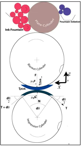
process such as laser, ink jet and reprography (photocopying) technologies. Figure 1 shows the geometry and disposition of the process with a free-body diagram of the forces acting in the printing nip. In accordance with paper physics literature, the coordinate system used in this dissertation defines z as the vertical direction. x is the direction of the flow and y is perpendicular to the x - z plane.
In this research it has been chosen to work with a single color machine running black ink under an optical density of 1.8 according to GRACoL® conditions —General Requirements and Applications for Commercial Offset Lithography—. The problem assumes full ink coverage with ink flow in the range of 1 gram/m2 and with ink layer height of 2 microns (2 x 10⁻⁶ m). The substrate considered is coated paper treated as an engineering material for which its anisotropic tensile and yield conditions are known and constant.
x z
In SFO, ink is fed to a printing plate, through a series of rollers constantly oscillating and rotating (ink fountain), kneading the high viscosity thixotropic fluid. The plate has been impregnated with a fountain solution mostly composed by water keeping non image areas free from ink (waterless process keeps non image areas ink free by surface condition of the siliconized plate but here we consider wet offset). At plate contact, ink is emulsified by the fountain solution —up to 20% in volume—, (Eldred, 2001). Then, the plate transfers the image on to the rubber-like surface called blanket. Since the image does not transfer directly onto the substrate, but rather is offset to the blanket, the process borrows its name from such characteristic.
At the final step, the image is transferred to the substrate under the action of high contact nip pressure —1 MPa at the center—, (McPhee, 1996). As the substrate leaves the printing nip, grippers pull the sheet from the blanket breaking the adhesive force of the ink. A direct consequence of the analysis proposed in this research is that the problem is twofold. There are two regions to the printing problem. One, as ink and paper interact inside the contact nip and, second, as the paper splits from the blanket at nip’s exit. The flow problem changes boundary conditions from one region to the other and it should be treated as such, in contrast to traditional approaches, which have considered the problem as a single region phenomenon, (Dubé et al, 2005).
1.3 Substrate’s Runnability definition.
important than paper notches as traditionally thought. He also studied a notch in the paper web under fracture mechanics to identify the instances of failure. He concluded that impurities, which are traditionally the result of house maintenance issues in the paper mill, are far more influential in the randomness of breaks.
Fellers et al (2006) presented an extension of this work where cellulose fiber features were changed in order to characterize web brakes. The idea was that a crack grew under tension and speed in web offset. Its growth varies depending on the differences of stock-furnish —paper composition—. However, this concept cannot be applied to SFO.
Clearly, in SFO, cracks are not important and hardly ever found. Press speeds, as well as tension applied on the sheet, are not enough for propagating an eventual crack. The same happens to impurities in the paper. Their possible influence would be to increase the probability of picking —localized surface failure— and not paper tear. McPhee (1996) contributed to the field by studying forces inside the press nip and the interaction of blanket and ink tack (vertical force exerted by the ink on the surfaces while splitting). He made a first formal approach to summarize the physics of the printing press in engineering terms.
Under McPhee’s approach, the concepts of flow, pressure, elasticity and the combination of factors at the nip both for ink/paper as well as fountain solution, are brought into engineering terms. The current dissertation uses free-body diagrams and mechanics of fluids approach to understand the issues at the printing nip by providing adequate solutions to NSE under suitable boundary conditions and the resulting forces on as ink splits from the blanket pulled by gripper tension.
Based on the above definition, a ratio between substrate’s surface strength and ink tack at nip’s exit serves to define Runnability in z-direction but, it is not sufficient since ink extension is a function of the parameters involved as shown further in this work. It is demonstrated in Chapter 5 that ink extension can define Runnability in z-direction in an adequate manner by identifying regions where paper splits properly form the blanket.
Consequently, substrate Runnability is a directional property of a sheet in SFO where, in z, it depends on ink adhesive forces as well as its own internal strength and, in x-direction, it determines paper elongation as grippers pull the substrate from the blanket. In this current work, only the adhesive action in z-direction is considered and its influence on paper surface strength.
1.4 Framework and literature review.
ink and paper hues and, image expectations for specific paper grades under fully-developed conditions.
The printing process, in engineering terms, makes sense under GRACoL® 8.0 since variables such as substrate elongation, ink flow and heat transfer can be calculated based on assumptions for steady conditions and fully-developed regions. Then, NSE as well as mechanical (free-body diagrams) and heat equations can be considered steady. A GRACoL® certified process supports a printing operation running at constant regime.
Transient conditions for ink flow, such as ink tack build up until fully-developed flow are of interest Boonkuernoon et al (1994). However, in this dissertation the transient portion is not considered for the solution of NSE but rather to understand the non-Newtonian function for ink under the Power Law model. Since ink tack build-up occurs in a range of hundreds of seconds (Gane et al 2003) and the printing nip interaction occurs at a typical time of 0.004 s — consider a contact strip S = 12 mm, press running at 10000 sheets per hour or 3 m/s —, ink tack and viscosity can be assumed constant during the analysis since there is no time for any appreciable change. Solutions to NSE presented in this research show that the vertical splitting force is governed by viscosity, ink layer height and splitting velocity in accordance with Stefan’s law and not by ink tack build up since viscosity, either Newtonian or not, remains constant, at constant temperature (as shown in Appendix 1), during the interaction .
1.4.1 Ink tack, ink flow and substrate physics.
Porosity might influence initial ink tack as suggested in the literature (that effect is not supported in this dissertation as the influence of porosity on the flow is proven to be very small) In any case, porosity would not have any reason to make changes in tack force unless the penetration velocity into the substrate would be very fast. Additionally, the ink layer used for tack-o-meters runs 15 or more times thicker than the actual press —30 to 50 microns instead of 2 microns— and results might not be comparable.
A more suitable ink tack test is made at the IGT apparatus (at the paper lab), where ink layer height and velocity are managed to create surface fracture on a paper substrate, (Rand, 2004). On the IGT, it is commonly observed that thinner ink layers increase ink tack (Gerli et al. 2012) contrary to McPhee’s (1996) and Xang’s (1993) observations.
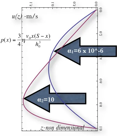
In the current dissertation, ink flow is analyzed as a thin channel with either a non-porous or a bottom porous surface under fully-developed conditions. Solutions for NSE under a thin channel model and the further separation of surfaces provide an increase in the fluid pressure inversely proportional to ink layer height (p-p0 proportional to 1/ hn+a where a = 0 models Newtonian fluids and a ≤ 0 for shear thinning non-Newtonian fluid under the Power Law assumption).
1.4.2 Mechanical properties.
Substrate mechanics is studied here by traditional Hooke’s law as set by Kent, (1925). Strain is treated in the same way as a beam subject to tension. The concept of a rotating brake is used to model forces acting on the printing nip through a free-body diagram including forces holding the sheet in the nip while being pulled by the grippers (see Appendix 2), Shigley (1977). The solution to the free-body diagrams provides differential equations for common static problems that relate ink pressure field and mechanical forces.
Roll contact theory set by Hertz (1895) further formalized by Bejan (1988) aids in the understanding of blanket and substrate contact areas. As stated by Hertz, the area inside the printing nip depends on elasticity coefficients of the surfaces and the interaction of surface asperities. The same contact area is useful in understanding heat transfer of a set of rollers using the low Prandtl number model proposed by Bejan (1998), presented in Appendix 1. We make use of Bejan’s model to identify the constant temperature condition needed to validate solutions to NSE obtained here ,identifying the steady heat flow of the SFO press.
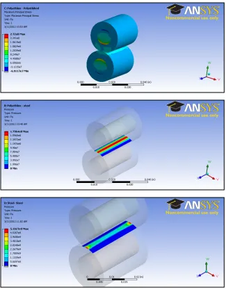
Ansys™ is used to provide Finite Element Methods —FEM— solutions to measure and correlate contact pressure inside the printing nip. It is found through Ansys™ visual results that the contact area forms a rectangle, which is in accordance with Hertz formulation and, that, contact pressure peaks at the middle of the printing nip.
Contact pressure obtained from Ansys™ can be further fitted by a form of a sinusoidal function suitable in the solution of NSE since it provides wall pressure in accordance with observations by McPhee (1996). He used a function of the form p(x) = p0sin(πx/S). With p0 being the maximum contact pressure (in the order of 1 MPa), and S, the contact strip’s length. Ansys™ analysis made on this dissertation provides the same shape of the contact pressure function used by McPhee with the added expected result that, the harder the surfaces in contact, the steeper the slope of the contact function.
in order to study sources and locations for delamination on such substrate. In the current dissertation, finite-element analysis is not used for delamination or for picking. Adequate ways to implement FEM in adhesion require using adhesive FEM elements, which are not available with Ansys™ under NC State license and, the results would not be meaningful. Instead, traditional solid mechanics is applied. Ansys™ Workbench is used in this work to study contact between two rotating cylinders made of different materials and flow in a thin non-porous channel. Ansys™ results are very useful since the actual evaluation of forces in the printing nip is not an easy set up.
Sudarno et al (2006) made use of a model of ink forces acting on the paper surface. They proposed a force, due to paper absorption, as a theoretical model and then proceeded to make press laboratory tests. The source of that alleged force is not clearly identified. As a contrast, in the current dissertation the approach is that forces resulting from the pressure field inside the ink must come from proper solutions to NSE under reliable boundary conditions and not from pre assumptions of the solutions.
Data from Niskaaken (1998) summarizes parameters such as Young’s modulus in x and z directions, friction coefficients and, Lucas-Washburn equation for fluid penetration into paper under offset printing. Actual parameters for the problem are used since the printing problem requires presenting results based on actual numbers to determine whether the solutions obtained are relevant or not. For example, by plotting pressure and force solutions coming from NSE, the researcher can identify whether results pertain to the problem or not. One case at hand, presented in the current research, is the over-estimation of splitting pressures that have prevented previous researchers from understanding and assessing the validity of Stefan’s law, (Dubé et al , 2004), Voltaire (2006).
paper proposing that paper inside the nip can be treated as an orthotropic material for mean fiber angles close to 45º. Szewczyk used the theory of composite materials where fibers are oriented at arbitrary directions with respect to the 0º plane. This approach is amply explained for a multilayer material on the methodology proposed by Daniel et al (2006) where layers at different directions can be summed up to a single Young’s modulus at the 0º plane direction. Such case might be extrapolated to coated papers as press grippers pull the stock through the printing nip.
Accurate estimations of the orientation angles of different coating layers in printing papers are yet to be studied and whether multilayer methods for composite materials are valid for paper as a possible alternative for predicting paper elastic properties. Different layer formulations, thickness and fiber orientations would have to be introduced in order to anticipate the overall behavior of the substrate under plane stress, which is the condition of the printing nip.
Since that work is still under development, in this dissertation the use of a single parametric Young’s modulus for an anisotropic substrate is used to study paper‘s mechanical conditions, particularly on z-direction.
Toshirau et al (2006) studied the static friction coefficients on calendered and non-calendered sheets. They study how coating components affect surface lubrication. Clearly, highly calendered coated surfaces present higher static friction coefficients, which lead to steeper blanket release angles at the exit of the printing nip. Static friction coefficient influences forces in x and z directions.
1.5. Solutions for flow in a porous channel.
Berman (1953) provided solutions to NSE —based on Blassius stream functions— for flow in a channel with one porous wall. Berman’s model is used in this dissertation as an initial tool to understand ink flow in the printing nip with a bottom porous wall. As the similarity model is applied to the printing nip problem, we found that the solution does not capture the influence of porosity for the printing nip. The solution provides a velocity profile similar to a Couette flow but it is totally unaffected by bottom wall porosity. A complete discussion of the similarity solution as compared to the Lubrication Approximation Equations —LAE— for the printing nip is provided in Chapter 2.
Dubé et al (2005) were the first team to introduce LAE to the study of the printing nip on their work on hydrodynamics of ink transfer. They confirmed that, at constant porosity, fluid transfer increases with smaller pore size. They made use of the high aspect ratio ε inside the printing nip since ε = h/S approaches 0 —for typical printing parameters ink layer height h = 2 x 10⁻⁶ m and S = 0.012 m is the length of the channel—. As they studied ink flow inside the nip for a single printing dot they proposed a formal definition of ink tack as the force pulling form the substrate’s surface. In their work, there were explanations for regions where Stefan’s law might or might not work. However, they did not provide a solution of NSE with a porous wall. In the current dissertation their work is extended to introduce porosity at the bottom wall and non-Newtonian conditions both for a single dot as well as for the full contact strip S. We found two important facts. First, Stefan’s law applies fully to all regions and conditions, as ink splits from the blanket (not only to some particular area as suggested by Dubé et al.) and, second, porosity barely affects ink flow. Their ink tack definition is substantiated within the current research as the ink pressure field (resulting from solving NSE) multiplied by the contact area.
assures that results obtained in the current research represent the flow and the physics inside the printing nip under firm mathematical framework.
Panton (2005) provides detailed derivation for the porous channel under the LAE as well as the similarity solutions based on making a set of two differential second order equations into one fourth order equation. In this dissertation, LAE approach is used to study both, the flow inside the nip as well as, the adhesion problem at nip’s exit. We observe, as it will be shown in Chapter 2, that LAE provide the best model to understand the printing nip problem over similarity solutions since similarity can not predict any sensible effect of porosity for this very low Reynolds flow.
1.6 Stefan’s Law and ink tack in the printing nip.
Debate surrounds the application of Stefan’s Law on the forces related to the ink layer height on splitting. As noted above, McPhee proposes a completely opposite view by suggesting that splitting forces increase with ink layer height. Traditionally, first due to the geometry of the printing nip —different from the immersed disc as proposed by Stefan— and second, due to the absence of capillary action and the presumed presence of cavitation, Eldred (2001) and Voltaire (2006) have argued that Stefan’s solution does not apply to the printing problem. In actuality, pressures inside the nip are much higher than any capillary action, (Niskaaken, 1998) and, consequently, the capillarity argument is not important inside the offset printing nip.
initial ink layer height decreases to the power of -3 (h-3). Ink tack increase could be higher depending on the viscosity model of the non-Newtonian fluid. The Días and Miranda solution, made under cylindrical coordinates for a tack meter apparatus, correlates with the solution proposed in the current dissertation under rectangular coordinates. Both contradict McPhee and correspond to observations made on press as well as press troubleshooting techniques proposed by Oresick (2004). Xang et al (2000) proposed that on roller-to-roller action, at the lab in the ink-o-meter, the higher the ink film height, the higher is the splitting force. The rationale for this observation is not clear since at the IGT apparatus lab tests prove other wise, (Gerli et al, 2011). In this dissertation, under proper solutions of NSE and printing boundary conditions, we clearly established that Stefan’s law duly applies at nip exit and has no influence inside the nip as the walls, prior to splitting, drive the flow. The argument by Voltaire (2006) is that Stefan’s law predicts forces far above the actual forces observed in printing at splitting. In this dissertation, it is proven that the law does apply once the proper region of influence is considered, which cannot be bigger that a square which side is limited to the ink layer height. At the first micron of ink splitting, the forces predicted by Stefan correlate properly with the capacity of common substrates to withhold force in vertical z-direction.
1.7 Ink tack definition.
—McPhee suggests they are measuring torque—. This digit however, depends on the rpm at which the test is made. As an example, one manufacturer could report 12 for some particular ink at 800 rpm while a competitor could report the same number at 1800 rpm. The former case implies a much higher torque in the roller-to-roller ink-o-meter. In practical terms, the number has no meaning. The implications for strain rate on ink tack are measured and discussed by Voltaire et al (2002) where, as expected, higher strain rates mean higher tack readings expressed as ink-splitting force.
Furthermore, in the pressroom, the definition of ink tack is far from standard. Ink cans at any print shop have labels reading low, medium or high tack without providing any relevant information. Printing organizations and schools such as PIA —Printing Industries of America or RIT —Rochester Institute of Technology— recommend printers suiting their own ink to the stock they run. This dissertation furthers on the definition set by Dubé et al (2005) in terms of the solution for the ink pressure field under NSE, multiplied by the contact area and, in accordance with the Días et al. solution (2012).
Pangalos (1983) states that, for sheetfed printing, where speeds usually run below 3.5 m/ s, viscosity controls ink film splitting. Xang et al (1990) corroborate that assessment, which is in line with NSE solutions obtained in this current research. There seems to be no reason why at higher velocities than 3.5 m/s viscosity would not control ink tack. Solutions for NSE presented here support the fact that viscosity affects tack at any velocity such as ink layer height and splitting velocity.
and compares the results. We identify that the influence on the velocity profile of the flow between a Newtonian and a non-Newtonian ink is very small and that the value of the exponent a, on a non Newtonian model for an offset ink is very close to zero. This is done by using, as a basis, data provided by Voltaire et al (2000) on ink tack rise under various percentages of ink emulsification.
Havlı́nová et al (2002) measure the thixotropic behavior of common cyan, magenta, yellow and black inks. They correlate it to the Ostwald flow model (an extension of the Power Law model used here). It is clear that inks corresponding to non-Newtonian fluids cause higher shear stresses. The same result is obtained analytically in this dissertation by solving NSE for non-Newtonian fluids under the Power Law model. However, it is clear that offset inks (from the analytical analysis) do not deviate much from the Newtonian model.
1.8 Offset inks.
Work by Pangalos (1984) shows the implications on the rheological behavior of different ink compositions. It would seem that a global ink viscosity definition would be somewhat misleading since ink composition could play a large role in the final outcome of the fluid ‘s behavior. In any case, for the range of interest on sheetfed printing, related literature concludes that ink viscosity remains constant for the temperature and composition used in most applications (Fernández et al., 1997). The solution for the flow at nip’s exit presented in this dissertation, yields the vertical force of the ink—in z-direction or ink tack— as a direct function of its viscosity, splitting velocity, ink layer height and contact area resulting from the pressure field solved from NSE. Then, if the ink viscosity is known, ink tack can be anticipated (by solving the pressure field from NSE) under known ink film thickness and press speed. The resulting splitting force can be compared to the actual z-strength of the substrate as a tool to anticipate picking. Under those conditions, in this dissertation we present regions of proper and critical Runnability in z-direction as a function of ink extension during splitting anticipating substrate’s delamination as well as surface failure or picking.
Mattila et al (2006) explain how blanket smoothness is a factor contributing to splitting forces. That idea is considered in this dissertation to help explaining that smoother contact surfaces allow for lower ink layer heights, which in turn increases the forces needed for splitting ink from the blanket.
1.9 Cavitation.
From the earlier work in the field of ink splitting, Zang and Aspler (1993), to Eldred (2001), Voltaire (2006) and others, have presented solutions —mostly inferred— to the ink flow where they assume the presence of cavitation at the end of the thin channel. At the onset, Zang and Aspler report ink pressures so low at nip’s exit that cannot be physically reached —see Figure 2—. They even presented negative absolute pressures.
to be present. The search for proof of pressure drop is furthered by looking for sound waves of presumed expanding air trapped in the flow. Figure 3 illustrates the ideas on which that model is based. It has been assumed that the presence of cavitation in this flow is beyond any doubt and that surface deterioration can be explained from that apparently unquestionable fact, (Eldred, 2001). The current dissertation proves otherwise. Several annotations can be made to their observations. First, the intuitive idea of contact pressure rising in the middle is validated by Zang and Aspler’s work and expanded by McPhee’s 3 years later as shown in Figure 2 below. Nevertheless, it is unclear where and how does the pressure drop happens and how did they measure that occurrence.
The idea of pressure dropping below atmospheric and, the subsequent presence of cavitation has since permeated research in this field and prevails in the analysis of the printing problem. Voltaire (2006), more than 20 years later, assumes cavitation again. In any case, Zang’s report of the value of pressure drop defies reality and cannot be taken into account. The idea of pressure falling below -0.11 MPa (absolute zero) makes those findings unreal.
Figure 3. Model for ink flow including assumed cavitation.
In Figure 3, Voltaire (2006) suggests that ink flows within the nip creates suction on the surrounding air, trapping air bubbles that would expand at nip’s exit (while ink splits from the blanket), causing two major phenomena: first, the air bubble is expanded until it separates creating ink misting in the form of very small ink droplets and, secondly, the pressure fall is such that the suction generated by the expansion and implosion of air is capable of destroying the substrate’s surface.
for Newtonian and non-Newtonian conditions and, second, to the adhesion solution at nip’s exit, following the approach by Dias and Miranda (2012). It demonstrates that splitting forces can be anticipated by proper solutions of an adhesion model at nip’s exit.
At this point, qualitative observations can be soundly made on the propositions presented by Zang, Voltaire and Eldred on the assumption of cavitation. Initially, the idea that air is being sucked into the flow defies common physics. Offset printing occurs in an open environment where the flow is exposed —in all boundaries, besides the top and bottom walls — to atmospheric or gauge pressure. Inside the nip, pressure rises to 1 MPa due to cylindrical contacting surfaces pushed one against the other. Nip pressure would obviously act as a wall impeding any presence of surrounding air being trapped in the flow. There are no regions of high flow acceleration reaching sound speeds, where shock waves or the like could be generated.
Furthermore, assuming that pressure at nip’s exit could fall into the vapor range at around -0.1 MPa (with assumed suction pressure absolute value of σTack== |-1 x 10⁵Pa| ), one could estimate the ratio between this lowest assumed pressure to the actual surface strength of a paper sheet at around σyield-z = 0.2 MPa. It is readily observed that even under the very unlikely presence of cavitation, the supposed suction created by the air implosion would not be enough to cause surface damage on the paper (picking). In the worst case, it would be at 50% of the pressure needed to cause surface damage. Such pressures are far from being observed in this problem. That fact is demonstrated here by proper solution of NSE under common printing boundary conditions.
assumptions do not comply with a fluid flow qualitative analysis. Finally, the presence of filamentation, if ever observed, would not directly mean cavitation since, filamentation of any fluid (e.g honey) could occur even at very low splitting speeds at atmospheric pressure and far from any pressure drop. Flow analysis in Chapter 3 shows the very low possibility of pressure drop to be observed in this problem.
As a corollary to this discussion on cavitation, inside or outside the printing nip, it is important to indicate that the solutions presented in this dissertation for the momentum and continuity NSE under LAE do not support the presence of cavitation and, furthermore, the consequent rattling sound of cavitation would be observed in the ink train and damage to those roller surfaces would also be observed. Certainly, that is not the case in SFO.
The adhesion solution shown in this research is proven to be the proper way to solve the problem instead of looking for cavitation in regions where it most probably will not occur. Absolute pressures needed to reach vapor conditions for the water emulsified in the ink are in the range of 2 kPa (oil in the ink would require 1 kPa absolute) and, from the solutions of NSE, those low pressure regions would not be observed since the overall process is always exposed to atmospheric pressure. This dissertation proves that the possibility of cavitation would be observed at speeds at least 3 to 4 times higher that what is commonly run on a SFO press and hence the assumed presence of cavitation would be rather uncommon if ever observed.
1.10 Ink and Heat Transfer.
Appendix 1, based on work by Bejan (1989) where contacting rollers are studied as a case of extremely low Prandtl numbers. Under Bejan’s idea, heat transfer is measured as if the contacting surfaces would act as fluids with a very thin momentum boundary layer. That solution is compared to traditional heat transfer methods based on slippage of the inking rollers, roller speed and contact heat generation (McPhee, 1996). The use of the low Prandtl number proposed by Bejan (used in Appendix 1), proves to be a far simpler and a very accurate prediction for heat transfer in the inking unit. Work presented on Appendix 1 corresponds to actual field measurements. It is observed that temperatures of the ink/fountain solution emulsion are well below the 36ºC range and hence the fluid is uniform, incompressible and homogenous. The results of the experimental work made on this research, on two actual printing presses, running under steady GRACoL™ conditions supports the simplifications of the heat terms in NSE and validates the application of LAE to the printing nip problem as presented here.
1.11. Walker- Fetsko and ink immobilization.
In their studies of ink transfer Walker and Fetsko (1955) later followed by Xang et al., (1993) and then Rioux, Xang and Bousfiled, (1995) consider ink flowing into the porous region and later separating under the empirical formula shown below:
Y = A(bB +f(X-bB) (1.1)
Where:
Y =Amount of ink transferred to the paper per unit area X = Initial amount of ink on the printing plate per unit area A = 1-e-kX — Coverage function
B = 1-e-X/b — Immobilization function k = Printing smoothness parameter
It is clear from Equation (1.1) that the formulae does not correspond to a solution for any type of NSE model. The work involves important experimental correlation and, if the proper parameters are chosen, the equation correlates well with the amount of ink transferred to the paper from the blanket.
The idea of immobilization of ink has not been observed and does not comply with any sound consideration of the physics of the problem. The walls are at the same temperature and velocity at the wall is no reason for ink to remain idle at substrate contact at any time aside from a non slip condition for the flow. Experimental work by Schoelkolpf, (2000) does not support the filter cake idea (immobilization at the walls) either.
Walter-Fetsko and their supporters do not consider neither Darcy’s law nor any porous flow solution such as Lucas-Washburn equation. Consequently, the idea is based on fitting parameters. It does not explain the physical events taking place in the printing nip since there is no account of nip pressure, forces or velocities involved in the flow and its subsequent influence on the substrate. In the current dissertation the approach by Walker-Fetsko is discarded for its inadequacy and lack of explanatory power.
1.12. Paper absorption.
be modified to predict the behavior of small pores and that coated structures support higher ink tacks.
In this dissertation, the result of NSE under LAE will help assess the influence of a porosity equation on the ink flow. The porosity function could be null, constant or, have any arbitrary form. The solution of NSE would capture porosity’s influence on the flow as a decaying profile of the velocity field resulting from the porous boundary condition. It is observed, from the solution to NSE obtained here, that the influence of substrate’s porosity is small on the actual ink flow. Despite the form of the porosity function, using LAE permits assessing such a function in the solutions as a tool to predict mass transfer to the substrate. In this dissertation two cases are discussed. First, no porosity and, second, constant porosity. Random porosity is not treated. It would be anticipated, from the solutions here, that its influence on the flow would be minimal for typical substrates since the penetration velocities into the substrate are rather small as compared to the velocity of the flow as demonstrated in Chapter 2.
1.13 Other Factors.
transfer of around 1 gram per square meter, while it splits from the blanket. Microphotographs made on that study support the general observation that, 1-micron ink layer stays on top of the paper as the 2-microns of ink initially on the blanket split evenly. These findings are instrumental in this current research to estimate ink layer height h, both within and outside the printing nip.
Sampson et al (2006) analyze pore size distribution of the sheet through a stochastic approach. They find a relationship between porosity and mean pore diameter. This pore size dat is used here to model the pore diameter and calculate the flow velocity into the pore by a modified Lucas-Washburn equation for the printing nip based on Nikaaken (1998) formulae.
1.14. Blanket and paper elasticity.
Uesaka et al (1980) present a visco-elastic approach for paper. They provide a way to understand Poisson’s coefficient on sheets —the ratio of transverse contraction to longitudinal extension in the direction of stretching force— as the substrate travels the printing nip by considering paper as an isotropic material for the x - y plane. With x being the direction of the flow and y the perpendicular (depth) to the x - z plane, (Figure 1).
The concept of substrate elasticity in the z-direction is considered negligible in the current dissertation since, at a contact pressure of 1 MPa the compressibility of the paper is virtually unaffected (Niskaaken, 1998). Elasticity in the channel is observed at the compression of the blanket rather than paper or ink. For instance, at 1 MPa a typical 2 mm thick printing blanket would compress 10% or 0.2 mm, which is 105 times more that the actual ink layer height. So the blanket will deform to conform to ink flow and prevent any paper deformation in the vertical direction. In this research, this fact is used to provide justification for the thin parallel channel geometry, which is also supported by solutions using Ansys™. At the common nip pressure of 1MPa paper is not elastically affected in z.
(1998). In paper strain, this factor could be negative which would indicate growth in the y-direction as paper travels the nip. The effect is commonly called paper fan-out (or fan-in depending on the case). In reality in the pressroom, significant strain is observed for relatively lightweight substrates commonly called text weights. For cover weights, stretch events are not usually observed under the forces at play in SFO printing. The study in this research has focused on the effects of ink splitting as ink/paper are released from the blanket in z-direction. It corresponds to the most common failure phenomenon in printing as small surface particles fail under the action of the ink adhesive force (picking).
1.15 Printability.
Printability (the ability of the process to reproduce on the substrate repetitive images very similar to the original) is closely linked to at least four major factors. Namely: press adjustment, sheet formation, fluid flow and optical characteristics of both ink and paper. Laurent (2002), in his doctoral dissertation provides a definition of the term applied to the field of Flexography. His approach is to evaluate both, qualitatively and qualitatively the substrate, ink and press conditions to create a pondered Printability index, Pi. That work can easily be extended to paper printing on lithographic processes. In the current dissertation it is assumed that printability for the substrate is uniform. In other words, the ink layer through the channel maintains constant height h, so that the expected image reproduction (measured as optical density) is constant.
Sadodnikov et al (2008). Both works make use of cyan printed samples in order to compare what the human eye sees in contrast to a scanning algorithm. Chinga et al (2007) make use of freeware applications to analyze formation and anticipate areas prone to picking.
Despite the existing analysis, some paper manufacturers prefer analyzing formation in a qualitative form. The implications of uneven print absorption (referred in the industry as mottling) is controlled by printing strips of paper on the IGT device —IGT is a laboratory tool resembling a small offset press manufactured by IGT Testing Systems from Holland— , grading the printout by comparing it to a custom template. For instance, they assign a number between 1 and 4, where 1 indicates bad formation based on the mottle result on the IGT and 4 indicates good ink lay. In every day practice, coated paper manufacturers prefer this option since it is more in tune with day-to-day production and quality analysis. The rationale behind this assessment by the manufacturers is that, a printed sample, is a better judge for mottling —random ink absorption changes— than an unprinted scanned image.
In this dissertation, the printed piece is assumed to have even ink lay under full image coverage. That is the case where the highest mechanical forces are observed and the uniformity of the image (ink layer) is assumed to be constant. This is also the case for the actual pressroom. The presence of absorption variations (mottling) is an exception considered as a substrate defect but does not represent the majority of the flow analysis. It could, and it should, be treated as a special case (exception) of the general flow problem not as the main case although its importance in manufacturing is paramount.
1.16. Other relevant work.
since coating is viewed as a remedy for density variations that could be significantly reduced by changing the stage at which calendaring takes place. More uniform local densities correspond to more uniform ink absorption and, consequently, less mottling probability. In principle, a perfectly formed sheet would not need further processes since local variations would not exist. In practice, this is an unattainable goal and yet this procedural change, proposed on their work, would move matters in a radically different direction. Of the same importance is the fact that, a change in the calendering stage could also imply a productivity advantage for the paper mill which is directly linked to important cost reductions while improving the way paper runs on press and how it interacts with ink.
Laurent (2007) in an unrelated work based on flexography, emphasizes the same point by concluding that better surface smoothness implies less probability of image mottling and better ink absorption. Manguin et al (2006) evaluate mottling as coming from formation on z-direction and propose defining the function as the ratio of the standard deviation and the mean of gray levels on a solid print. This is the most common approach since mottling is being studied as the perceivable difference of printed images within a grid defined to a scanner. The interpretation of the information to the computer is typically done by inverse Fourier transforms.
Wallström et al (2007) identify relationships between coating thickeners, surface roughness, porosity and a new way of characterizing that effect by pair functions. They state that an increase in thickeners decreases roughness while increasing pore volume. This is a major relationship since coated papers rely upon thickeners. Pore volume constitutes a big determinant in Runnability since it is a well-established fact that small pores transfer ink better (at constant porosity). In contrast, big pores increase strength of the surface against picking particularly on coated surfaces.
Additionally, it is discussed that mixing different fiber sources in the formulation of coated papers —like in the case of post consumer content— usually results in a coarser surface more prone to picking as well as print unevenness.
Manguin et al (2006) discuss that fact as well, as they anticipate that more coating and calendering do not improve local density variations but could even worsen them. This agrees directly with the conclusion from Lee et al (2007) since they sustain that coating is a remedy for a formation problem that could be addressed earlier in manufacturing. In fact, their argument is that resources spent at offline calendering would be better spent in line on the paper machine.
Chamundi et al (2006) based on measurements on the on Deltack ink-o-meter conclude that ink tack increases with speed. On their analysis on newsprint, they did not find this to be a source for linting —removal of loose fibers on the paper surface by the action of blanket/ ink adhesion—. They observed in tack rise with the increase of ink on the machine. This is a result similar to McPhee's (1996) but disagrees with the behavior of ink on SFO presses where lager amounts of ink result in less tack on the paper surface. This is explained, in the pressroom, as the result of the lubrication effect of the ink/fountain solution in the nip as well as the conformance to Stefan's law on porous structures as proposed by Dubé et al (2006). Proper solutions to NSE in this current research show that thinner ink layers increase splitting forces substantially as the resulting force is a function of h-3.
The explanation provided by Mattila helps understanding why black usually causes the most picking on the paper surface just because it is the first ink applied to the dry surface. In the case of the current dissertation, solving the problem for the single ink configuration (ink laying on dry paper) would be the worst-case scenario for picking and delimitation events.
Mattila et al (2006) also discussed the effect of blanket aging —the effect of continuos surface buffing by the constant contact with ink, cleaners and paper as the blankets remains longer on press—. This factor, often overseen in printing, is introduced as an additional parameter governing Runnability particularly on z-direction. Blanket tack increases with the amount of impressions due to the buffing effect that paper stock makes with every revolution.
Blanket’s friction coefficient increases as they interact with smoother papers. As a consequence, stretching and picking could result, Díaz (2011). Traditionally, printing organizations and pre-press manufacturers have recommended users that smoother blankets would reproduce a sharper dot. In their view, the smoother the blanket’s surface —highly buffed— the better. This recommendation does not take into account neither, the porosity of the substrate, nor its smoothness. Both influence printing dot holdout as determined by Magin (2006), Mattilla (2006), McPhee (1996) and others. Dot reproduction is highly influenced by the physics and chemistry of the paper surface and not only by the plate and blanket structures. In fact, latest research on paper structures, as cited here, shows that blanket selection, inks and pre-press color curves should be governed by the substrate and no the other way around. That is the principle upon which GRACoL® 8.0 sets its recommendations.
Kulachenko and Uesaka (2007) set the conditions under which paper is sensitive to humidity changes as it relates to fiber orientation. The important fact is that, after a change of around 5% in relative humidity, the ability of paper to go through the press is highly compromised once the stability of the surface is warped in the z-direction. They were able to identify that a change above 8% makes deformations on stock that could be permanent and make the substrate unprintable. In this current dissertation, the Runnability function is defined under constant relative humidity —RH— inside the pressroom. Printers continue to struggle with humidity variations within the pressroom. Humidity changes are rather common since many print shops control air temperature (through the A/C system) with very little control of moisture in the environment. Seasonal RH variations could make wave like deformations (cockling) in the direction perpendicular to the grain as the grippers pull the stock. Such deformations become permanent and the second side of the stock cannot be printed. Although this phenomenon is observed often on press, it had not been properly explained and modeled in the way Kulachenko did. In the current dissertation, the substrate is considered in the most stable, flat condition. Therefore, it is assumed to operates as a common engineering material under constant RH and temperature pressroom conditions.
1.17 Adhesion and other NSE solutions.
As mentioned on section 1.5, the problem of the printing nip has been traditionally treated in one of two ways. First, the empirical approach by Walker-Fetsko (1955) and second, a somewhat simple attempt to solve NSE for a thin channel under constant geometry and Newtonian conditions (Dubé et al 2006). Porosity at the bottom has not been duly considered within the printing/paper research as a boundary condition to the ink flow.
The problem inside the printing nip is customarily treated as a Couette problem by assuming the fluid in the channel moves while the walls remain idle. In fact, the solutions presented here are compatible with that model as flow in the middle of the channel lags the main wall velocity, very slightly nonetheless, and then matches wall velocity as the ink ends the channel length S. At nip’s exit, the substrate adheres to the blanket and grippers have to act on the sheet to release it from the rubber-like inked surface. The problem turns then, into an adhesion region where energy inside the fluid must be estimated to identify the necessary force to split ink from the blanket/substrate interface. On both regions (inside and outside the nip), NSE can be solved under LAE with well chosen physically reliable boundary conditions representing the actual problem.
One very important boundary condition is that the flow, both inside and outside the nip, is surrounded and open to atmospheric pressure, which promptly compensates for any pressure imbalance, should that ever occur. Then, the idea of cavitation is very far fetched in this scenario as the solutions to NSE further prove to be so. But more important is to identify that the problem is comprised of two regions and that prior attempts to reduce it to just one single region are not compatible with the physics and conditions of the printing nip. In this research, the problem is clearly split into two different regions where the materials and equipment interact in different forms.
channel in y is much bigger that the x and z-directions and the solution allows for mass conservation under a quasi 1-D model. In the same manner, flow is considered steady as there is no variation with time, it is laminar due to a very low Reynolds number and, finally curvature is negligible for the two circumferences coming into contact and then separating. The expected solutions are unique for the boundary conditions as proposed by Lu (1997).
Summary.
Chapter 2
Validation of assumptions. 2.1 Objective for Chapter 2.
On this part of the dissertation, the work is focused on demonstrating the validity of the assumptions made on the model for a thin channel, as an appropriate representative of the physics and geometry of the printing nip problem. At the same time, once validated the assumptions, the results are applied to previous work; in particular, the Berman-Blassius model (1950) and, the Hydrodynamics of ink transfer from Dubé et al (2004). The formulae from Niskaaken (1998) on ink absorption into a porous substrate is extended here to determine ink penetration velocity into a paper sheet, under a modified Lucas-Wasburn Equation for the printing nip/porous structure interaction.
2.2 Validation of assumptions.
Analytical models are as good as the assumptions they are based on. Figure 4 presents the model used in this research.
0.002 0.004 0.006 0.008 0.010 0.012x�m 200 000
400 000 600 000 800 000 1.�106 p�x��Pa
z
x