Design modification and Analysis of
Suspension Ball Joint Using Finite Element
Analysis
Jitendra Shinde1, Sunil Kadam2, Amol Patil3, Shamuvel Pandit4
P.G. Student, Department of Mechanical Engineering, Bharati Vidyapeeth’s CO Engg, Kandalgaon, Kolhapur, India1
Associate Professor, Department of Mechanical Engineering, Bharati Vidyapeeth’s CO Engg, Kandalgaon,
Kolhapur,India2
Asst. Professor, Department of Mechanical Engineering, Bharati Vidyapeeth’s CO Engg, Kandalgaon, Kolhapur, India3
Asst. Professor, Department of Mechanical Engineering, Bharati Vidyapeeth’s CO Engg, Kandalgaon, Kolhapur,
India4.
ABSTRACT:This study describes the analysis and investigation of the causes of the sudden failure of a suspension system ball joint. The axis of the ball joint element showed a complete fracture which occurred midway between the top and bottom section changes of the element. It is seen the ball joint of this car fails suddenly without any sign of consumption and this case is a dangerous as well as disturbing factor for traffic and driver. So there should be something else supports car when the ball-joint fails. This research has a modification of this ball joint for this purpose. Design of ball joint is modified and stress raisers are removed from the previous design of ball joint. Design of the present ball joint has been improved and from obtained results we can say that the design of ball joint is modified and within safety limit.
KEYWORDS: Ball joint, Modeling, Stress and Fatigue analysis, Design modification
I.INTRODUCTION
arms to the steering knuckles. They are used on virtually every automobile made and work similarly to the ball-and-socket design of the human hip joint.[5]
The front suspension system ball joint fails due to many of the parameters so it is necessary to study the exact reasons for the failure of ball joint in this it intended to observe these failures with the different tests. This projected study is an overall revive of existing ball joint failure and to minimize this failures by improving some failure parameters. So that it will helps to maximize life of ball joint and resulting minimizing road accidents.
II.RELATED WORK
From the literature review following possibilities are drawn because of the existing scenario of geometrical condition of suspension ball joint, boundary conditions and nonlinearity of material properties and some other parameters are required to study in detail.
II.MODELLINGANDANALYSISOFSUSPENSIONBALLJOINT
The measurements of main parts of ball joint have been made in order to create a three dimensional geometry by CATIA software. Then, the model (geometry) has been imported to ANSYS workbench software.
Initially the 3D drawing of ball joint is done by using CATIA according to dimensions specified in the Table:
Table No.1 Dimensions of Suspension Ball Joint
Fig. 1. 3D-Model
Diameter Dimension in mm
D1 30
D2 20
III. MATERIAL
According to chemical composition analysis by OES[5], the ball joint was manufactured using an EN 18D steel alloy. EN 18D Steel Alloy properties
:
• Young’s modulus (E) =190 GPa
• Yield stress=565MPa
• Ultimate tensile strength=887 MPa
• Density =7.85g/cm3
• Poisson’s ratio = 0.29
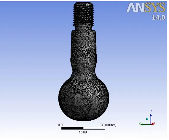
IV. MESHING GENERATION
Meshing of a given model will be done depending on geometry of the model, it is better to have more degrees of freedom hence more number of elements so that results obtained will be closure to analytical results. In two bay panel analyses, crack region is meshed with more number of elements when compared with other parts of fuselage, for obtaining a converged solution which in turn a better solution.
Fig B. meshing of ball joint
Fig. 2. Meshing of ball joint
V. LOADING AND BOUNDARY CONDITION
A load of (2X575X 9.81)N is applied downward to stud at the thread place in its longitudinal direction while other load of(2X575X9.81)N is applied horizontally at a place where it is in contact with knuckle, also a general joint is added to this region to keep only linear motion. A fixed boundary condition is applied to the socket at a place where it’s bonded to the lower control arm.
The fatigue stress and its safety factor have been created in these two forms of numerical analysis, the load on ball-joint is fluctuating between its maximum (where the ball-joint faces an impact) and the static load which only includes the weights of car, freight and persons.
Calculations for weight distribution on each wheel:
Kerb Weight: 1680 Kgs
Seating Capacity: 7
Gross Weight = Kerb Weight + Passenger weight + Luggage weight
WG = 2300 Kgs
From standard
The ratio of weight distribution is F/R: 49/51
Weight acting on each front wheel
W = (0.50X WG)/2
= (0.50X 2300)/2
W = 575 Kg
So, the reaction force,
P = WXg
= 575X9.81
P = 5640.75 N
P = 5700 N Appx.
Assumed condition is of bump, in which the extremity of load is present.
The load considerations are Double Gravity (2gacceleration)
P = 11400 N (taken for Analysis)
VI. RESULTS FOR ORIGINAL GEOMETRY
From the above loading and boundary condition following results are obtained.
Fig.4. Equivalent Von-Mises stress Fig. 5. Factor of safety
According to the von Mises’s theory, a ductile solid will yield when the distortion energy density reaches a critical value for that material. Since this should be true for uniaxial stress state also, the critical value of the distortional energy can be estimated from the uniaxial test
.
It is since observed that from the results, We came to know that, equivalent von-mises stress goes beyond ultimate tensile strength of the material and hence there is crack initiation in the ball joint at the specified loading conditions and that crack leads towards the fatigue failure of the ball joint as the ball joint is under cyclic loading as per the description given in the problem definition.
After the knowing results, it is need to increase diameter of ball joint at failure section from 15 mm to 17.5 mm and revise the design to get the desired results.
VII. RESULTS FOR MODIFIED BALL JOINT
For the same loading and boundary condition after design modification improved results for ball joint shown below.
Fig. 8.Equivalent Von-Mises stress Fig. 9.Factor of safety
We worked on the stress raiser in the previous design of ball joint and required design modification are done and results of stress and fatigue analysis of modified ball joint shows that stress value has been brought to the safety limit.
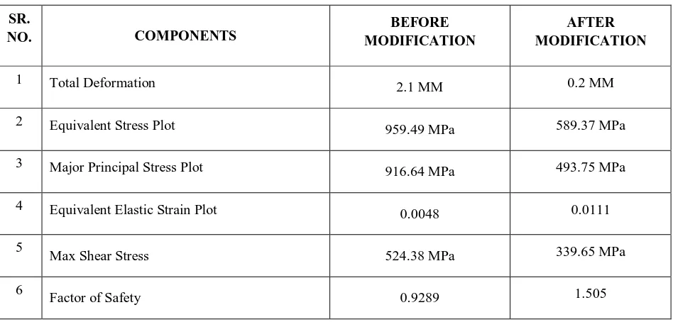
VIII. COMPARISON OF RESULTS
SR. NO. COMPONENTS BEFORE MODIFICATION AFTER MODIFICATION
1 Total Deformation
2.1 MM 0.2 MM
2 Equivalent Stress Plot
959.49 MPa 589.37 MPa
3 Major Principal Stress Plot
916.64 MPa 493.75 MPa
4 Equivalent Elastic Strain Plot
0.0048 0.0111
5
Max Shear Stress 524.38 MPa 339.65 MPa
6
Factor of Safety 0.9289 1.505
Table No. 2. Stress Analysis Results
SR.
NO FATIGUE COMPONENTS STRESSS CYCLE STRESS CYCLE
1 Fatigue life 264 (min) cycle/s 941 (min) cycle/s
Table No.3. Fatigue Analysis Results IX. CONCLUSION
The results for stress and fatigue analysis of ball joint with boundary condition for the previous ball joint tests shows that stress limit was crossed and the stress value is much higher than the ultimate tensile strength of the material, Also because of this there is no safe fatigue life to the ball joint .
REFERENCES
1.Agah Uguz and S. Hakan Oka, Bursa, “Finite Element modeling of ball joints under dynamic loading” Material prufungJahrg. 46 (2004) 10. 2.Bong-Su Sin,“ Process Design of a Ball Joint, Considering Caulking and Pull-Out Strength”, Department of Mechanical Engineering, Dong-A University, Busan 604-714, Republic of Korea, 2014.
3.Byung-Hyun Jang and Kwon-Hee Lee, “Analysis and design of a ball joint, considering manufacturing process”, J Mechanical Engineering Science, Vol 228, 2014.
4. Chen A., “Investigating the behavior of ball joint sealing boots using a 3D Finite Element Model”, 2nd Worldwide Automotive Conference, 2010. 5. E.A. Ossa, C.C. Palacio and M.A. Paniagua, “Failure analysis of a car suspension system ball joint”Materials Engineering Research Group, Colombia, 2011.
6. Fischer, I. S., “Numerical analysis of displacement in spatial mechanisms with ball joints”, Mechanism and Machine Theory,35 (2000) p. 1623-1640.
7. Fischer, I. S., “Velocity analysis of mechanisms with ball joints”, Mechanics Research Communications, 30 (2003)69-78.
8.K. Baynal, M. Makaraci, K. Gulbudak, “solution for failure analysis of automotive axle knuckle pull-out”International Journal of Automotive Technology 54−11
9.K. H. Lee and S. C. Hwang, “Structural dynamic analysis of a ball joint,” AIP Conference Proceedings, vol. 1499, pp. 394–398, 2012.
10. Krzysztof Siczek, Piotr Jóźwiak, “The existence of boron nitride existence in grease and how it influences the motion resistance of the stud of steering rod”. Technical University, 90-924 Lodz.2004.