Design and Development of Boost Converter
Using MC34063 for DC Input Led Driver
Adithya Ballaji 1, Akshith Monnappa K 2, Harshitha G.B 3
P.G. Student, Department of Electrical and Electronics Engineering, Reva University, Bangalore, Karnataka, India1, 2, 3
ABSTRACT: Boost converters are used worldwide in very gargantuan quantity as drivers for the purpose of LED Lighting. Here in this paper, a Boost converter using MC34063 is designed and developed which has a input voltage of 12V and constant output voltage of 24V for driving a 7W LED light. The developed circuit is different from conventional boost circuit as it eliminates the need for MOSFET thus also gets rid of external circuit used for providing PWM pulses for switching and in turn making the circuit compact and minimizing the switching loses. It has advantages like high efficiency, fast response and good stability. The circuit is validated through a hardware model and experimental results show that the output of the converter is constant and effectively drives the load of 7W LED.
KEYWORDS: Boost Converter, MC34063, LED Driver.
I. INTRODUCTION
In the neoteric years, the puissance and application of LED in the field of lighting has increased expeditiously, due to its improvement of high power and luminous efficiency. The positive impact of LED on the lighting industry is due to development and improvement of LED drivers. A LED driver is an electronic circuit which helps in managing the power to the LED or number of LED’s connected together which is done by acknowledging he changes in of LED or the circuit.
Step-Up (Boost) regulator are predominantly used as LED drivers produces high voltages which is mainly needed to drive the multiple LEDs which are connected in series which can be achieved through Boost or step-up regulator by providing constant supply of current (and hence brightness) there by mapping the LEDs requirement. LED drivers using boost regulators provide increased efficiency, low noise or interference, and short footprints. Someother characteristics comprises of precise LED current mapping, Schottky diode, and more than one output capability.
While the increase in urge for power in displays normally the high resolution colored one is persistently increasing. And due to very low power usage and increased and improved reliability thus LEDs are used as backlight for color displays, which includes those used in large screens like computers, tablets, and automotive displays. At present LEDs are available in market with various color combination. But an economic, easy and compact method for driving an array of LEDs needs to be found out for large scale application with low cost.
II. RELATED WORK
Over the years many new drivers have been developed due the increasing demand for LED lighting. And has become one of the important areas of research. A boost regulator is developed to achieve soft switching of the power switch. And a small fly back transformer is used to achieve soft switching [1]. Boost-Buck converter with high power efficient and double loop control strategy is developed thus using error amplifier with integrator control method [2].
implementing a successful LED driver [3]. With the advancement of technology came the closed loop control of converter. Especially the closed loop control of the buck – boost converter to maintain the high power factor [4]. Since the Output current of the converter is very important, a single stage fly back/boost LED driver with low output current ripple is presented [5].
Other notable work by researchers in the field of LED drivers include development of PWM and PFM controlled Boost converter for controlling LED lights [6] and providing an open circuit protection to a boost converter for a constant current source LED [7]. A high efficiency Buck converter using a Silicon carbide diode is developed [8] balancing of current plays a very important role a two staged LED driver with current balancing is developed for constant driving of LED [9].
Thus considering all the work which has been done in the field of LED drivers. Here a modified Boost converter using a MC34063 with a constant output current and voltage with low output ripple is designed and developed for LED driving. It consists mainly of IC MC34063 which eliminates the need for MOSFET and pulses to be supplied for the switch. There by making the circuit compact, less bulky and easy to design. The boost regulator produces a constant current and voltage output with low ripple. The design, hardware implementation and experimental results are presented in this paper.
III.CONVENTIONALBOOSTCONVERTER
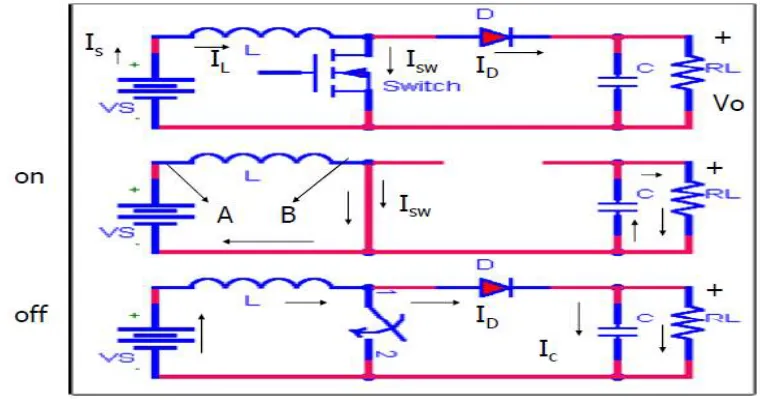
A boost converter or regulator (step-up converter), basically steps up the input DC voltage value and provides at output as per the load requirements hence the name step-up converter. The boost regulator mainly consists of a diode, a transistor which acts as a switches and normally one energy storage element. Capacitors are usually used at the output as a device for removing output voltage ripple that is hence only DC is available at the output and can be used along with inductor too sometimes, the below Fig. 1 shows the boost converter circuit with both ON and OFF condition along with waveform in Fig. 2.
Fig 1. Boost Converter circuit with ON and OFF modes
The operation can be explained in two modes of operation which is ON and OFF mode:-
ON time: The switch is closed to increase the inductor current From Imin to Imax linearly. During this stage, the diode is off and the load is completely supported by the capacitor. As a result, the capacitor voltage decreases. The switch current is same as the current in the Inductor.
OFF stage: The switch is turned off and the inductor current is now passes through the diode. During this stage, the power is transferred from the input to the load. And the output voltage is given by Vo = Vs/1-D.
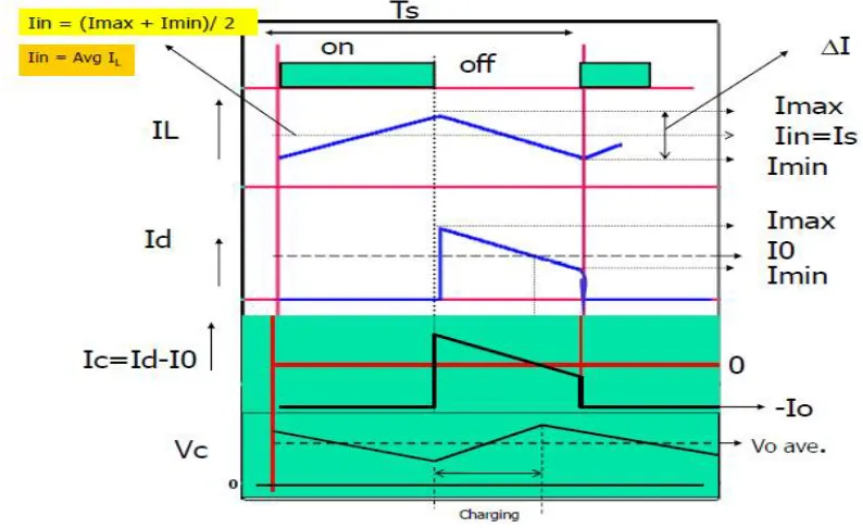
Fig 2. Output waveform for boost converter
Thus, the current in the inductor looks triangular in one switching cycle (Ts = Ton + Toff) as shown in above Fig.2. And IL is always positive and varies between Imax and Imin. The current ripple is = Imax – Imin.Input current (Iin): It is obtained by averaging the inductor current waveform. So Io = (Imax + Imin)/2
IV.BOOSTCONVERTERUSINGMC34063
Fig. 3. Boost Converter using MC34063
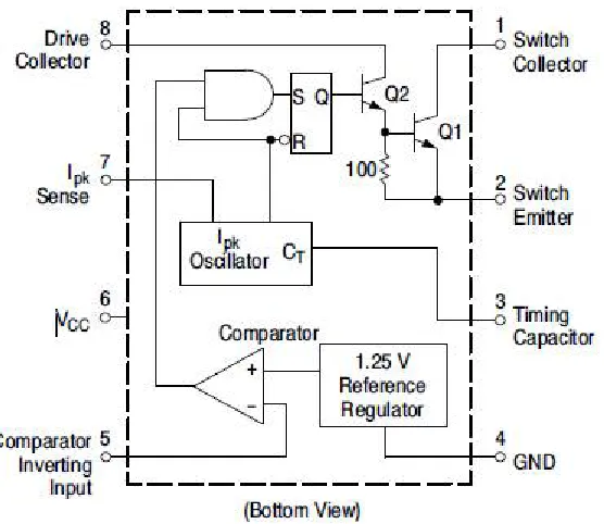
MC34063:-
MC34063 is a 1.5A step up/down and inverting regulator. It consists of monolithic circuit mainly for the DC-DC Converter operation. The schematic diagram is shown in Fig. 4 below. It consist of an internally built temperature compensated reference, current limit circuit, controlled duty cycle oscillator with an active, comparator ,driver and high current output switch. It has operating range of 3.0V to 40V and an operating frequency of 100 kHz with a precision of 2 %.
Some of the features of MC34063 are mentioned below:-
It can operate from 3.0 V to 40 V Input
The Standby Current is very low
It has inbuilt Current Limiting
Output Current of 1.5 A
It has Adjustable output voltage
Has a operational frequency of 100 kHz
It is capable of precision of about 2% for reference
It is available in Pb−Free Packages
V.DESIGNSPECIFICATION
Vinput =12V, Voutput = 24V, Vripple = 100mV/pp, IO= 375mA
C1= 100µF/16V, CO= 155µF/35V
CT= 220pF, Ceramic
R= 180E
R1= 1.2K, 1/4W,5%
R2= 22K, 1/4W,5%
RSC= 0.22E, 2W, 5%
LMIN= 25µH
F= 85 KHz
VI.HARDWAREIMPLEMENTATIONANDEXPERIMENTALRESULTS
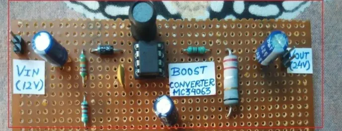
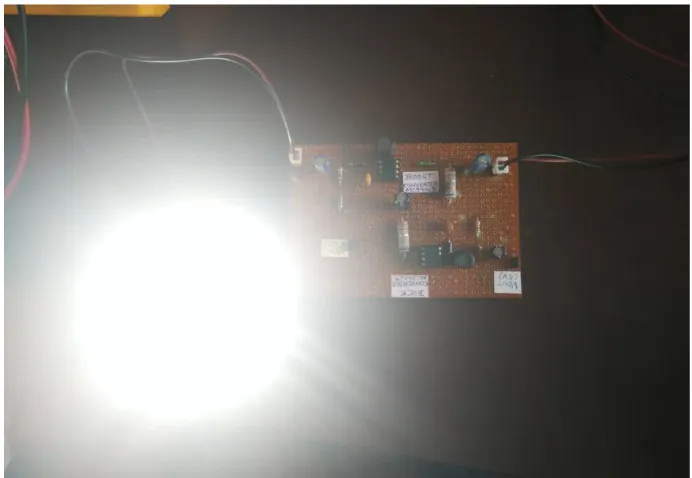
The hardware is implemented on general PCB board using the IC MC34063. It consists of an Electrolytic input and output capacitor. The input and output capacitor are used to reduce the source impedance and to improve transient response with improved stability respectively. The selection of the inductor and other components are done based on the formulas using the datasheet. The switching frequency is 85 KHz. The led driver can be powered from a 12V battery or even through a solar panel. The hardware prototype and experimental results are shown below Fig, 5 & 6 respectively.
The above Fig.5 shows the hardware prototype built on the general PCB board, it consist of a input and output capacitor which are electrolytic and ceramic capacitor.
Fig. 6. Boost Converter using MC34063 with an output of 24V
Here in the Fig.6 the boost converter is tested for proper Voltage output with 12V input from the solar panel. And it can be seen that the boost converter using MC34063 is able to produce required voltage of 24V.
From the above results it can be seen that the boost converter using MC34063 is able to produce a voltage of 24V with an input of 12V as shown in the Fig. 6. above and the Fig. 7. shows the boost converter driving a 7W LED.
VII.CONCLUSION
A boost converter using MC34063 IC is proposed, designed, and developed for LED Driving. The converter provides up to 24 V from a 12 V input supply for 7W LED at the output. As mentioned in earlier section it consist of an inbuilt temperature compensated reference, current limit circuit, controlled duty cycle oscillator with an active, comparator ,driver and high current output switch with an operating range of 3.0V to 40V operating frequency of 100 kHz and precision of 2 %. The converter is very compact, less bulky and eliminates the use of MOSFET for switching there by also eliminating the need for controller to supply PWM pulses for the switch. The converter developed is a low cost and can be used with solar power hence becoming a low cost LED Driver for solar based DC home lighting application for rural lighting.
REFERENCES
[1] Rayadhu Mannam, Nagesh Vangala, Vignan University, “Soft Switching Boost Converter for DC Input LED Drivers” Power Electronics (IICPE), 2016 7th India International Conference on 17-19 Nov. 2016
[2] Renbo Xu, Yongzhi Li, Lixin Zhong, Jiaming Liu, “Research on an Efficient LED Lighting Driver Based on Buck-Boost Driver” Circuits and Systems, 2014, 5, 153-159 http://dx.doi.org/10.4236/cs.2014.56017
[3] Michael Keene, Design Engineer, Endicott Research Group, INC “DC-DC Power for driving LED-Backlit LCDs” © 2010 Endicott Research Group, Inc.
[4] Chi Jen Huang, Ying Chun Chuang, Member IEEE, Yu Lung Ke. Senior Member IEEE, “Design of Closed-Loop Buck-Boost Converter for LED Driving Circuit” Industrial and Commercial Power Systems Technical Conference (I&CPS), 2011 IEEE ,1-5 May 2011
[5] Weiming Lin, Hongxin Chen, Shunyuan Ke, “Research on a single-stage Fly back/Boost LED Driver with lower output ripple” Power Electronics Conference (SPEC), IEEE Annual Southern ,5-8 Dec. 2016
[6] Yang Lu, Dariusz Czarkowski, Wieslaw E. Bury, “High Efficiency Adaptive Boost Converter for LED Driver” Compatibility and Power Electronics (CPE), 2011 7th International Conference-Workshop, 1-3 June 2011
[7] John Caldwell, Gregory Amidon, “Simple open circuit Protection for Boost Converters in LED Drivers Application” Analog Application Journal 4Q 2012 www.ti.com/aaj
[8] R. Srimathi, Shubhendhu Sitoke, S. Hemamalani, “High Efficiency Buck LED Driver Using SiC” Energy Procedia Volume 117, June 2017, Pages 224-235
[9] Tzu-Hsuan Kuo, Tsorng-Juu Liang, Wei-Jiun Wu, “Design and Implementation of a LED Driver with Current Balancing” 8th International Power Electronics and Motion Control Conference 22-26 May 2016
[10] Cheng-I Chen, Zhen-Ting Shao, Yeong-Chin Chen, “A DC-DC Boost Converter with High Voltage Gain for Distributed Generation” 5th Global Conference on Consumer Electronics 11-14 Oct. 2016
[11] Shafinaz A lopa, S. Hossain, M.K. Hasan, T.K.Chakraborty, “Design and Simulation of DC-DC Converter” International Research Journal of Engineering and Technology JAN-2016
[12] M. Ghanbari, S.M. Hosseini, “DC-DCBoost Converter Design and Development Based on Asynchronously Paralleled Switches” Industrial Technology 2008. ICIT 2008. IEEE International Conference on, pp. 1-5, 2008.
[13] B.M Hasaneen, Adel A Elbaset Mohammed, “Design and Simulation of DC-DC Boost Converter” Power System Conference, 2008. MEPCON 2008. 12th International Middle-East 12-15 March 2008