Modeling and Analysis of Temperature
Distribution in the Industrial Gas Fired
Powder Coating Oven using Computational
Fluid Dynamic (CFD)
Vaibhav C. Dhanuskar1, Pramod R. Pachghare2
P.G. Student, Dept. of Mechanical Engineering, Govt. College of Engineering, Amravati, Maharashtra, India1
Asst. Professor, Dept. of Mechanical Engineering, Govt. College of Engineering, Amravati, Maharashtra, India2
ABSTRACT: In this paper, study focused on the modeling and analysis of temperature distribution in the industrial gas
fired powder coating oven having dimension of 2700 x 1900 x 2700 mm3 is analyzed using Computational Fluid
Dynamic (CFD). The CFD analysis of existing oven with few modifications in geometry is done to achieve uniform temperature distribution. For CFD analysis ANSYS 14.5 is used. This study is particularly focused on the variations of pressure and temperature inside the oven. With the existing geometry of the oven, it is found that there is non-uniform temperature distribution inside the oven. Therefore, the geometry of an oven is modified. The Inlet opening to the oven is made adjacent to the bottom of the oven and inlet to oven through the perforated bottom. From the result, it is cleared that the inlet to the oven from slit adjacent to bottom and perforated bottom inlet shows uniform temperature distribution in the oven.
I. INTRODUCTION
Now a days, powder coating technology is used for engineering components to improve the life and surface finish of the components. Coating is a process of covering a surface of objects, called as substrate. The purpose of coating may be functional, decorative or both. The two important types of coating are [1]: Liquid coating technology (wet), which has been used for more than two centuries and Powder coating technology (dry), which has been used in Industries for some 30 years. The use of Powder Coating technology has been increased tremendously in recent years due to its relatively high performance over liquid coating technology. Various types of equipment are available for powder coating to small and large end users. The parts which need to be coated are grounded neutral so that the particles projected from spray gun can adhere to the parts and are held there until curing process is done in the oven [2]. The result is a uniform, durable, high-quality finish. The present analysis of oven is done at GUKSS Industries, Amravati. The geometry of gas fired convection oven is made and boundary conditions are analyzed. The problem in the oven at GUKSS Industries is uneven distribution of temperature. The CFD analysis is done to achieve uniform temperature distribution throughout the oven.
II. CFD MODELING AND SIMULATION
2.1. Oven geometry
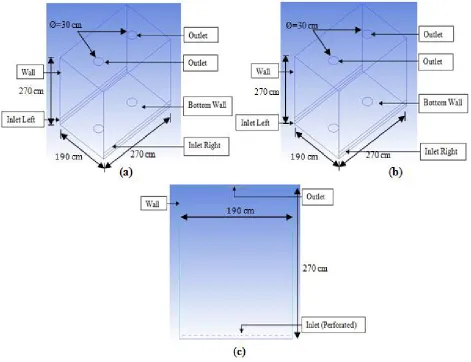
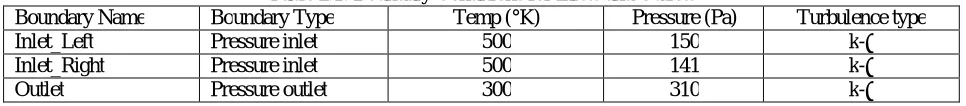
The dimensions of the industrial oven are a length of 270 cm, a width of 190 cm and a height of 270 cm. There is one burner which is situated in the centre of the top of the oven which has been designed to generate hot air from the combustion of natural gas. The hot air is then circulated through the supply duct by the air circulation fan and into the heating chamber. After the hot air has passed through the heating chamber, it then returns to the burner to be reheated, and finally back into the supply duct via a recirculation fan located on top of oven. The whole oven is surrounded by insulation made of glass wool, which is 10 cm thick. This is to stop the heat escaping to the atmosphere and make the oven more efficient. Modeling assumptions are taken into consideration and simplified geometries of oven with proposed modification are made in ICEM 14.5 as shown in Figure 2.1.
Figure 2.1:(a) Geometry of existing setup, (b) Geometry with position variation of Inlet Slit,
(c) Geometry with inlet through perforated bottom
2.2. Modeling assumption
the recirculation fan in a 3-D geometry is difficult to model because Fluent would not recognize that the flow could circulate so some modifications to the geometry were made. In order to overcome this problem, it is assumed that the air would exist in the system where it was drawn into the fan and enter through the supply duct. The fan inside the oven is represented with the pressure outlet and inlet which creates flow of air.
2.3. Boundary Conditions
Boundary conditions are a very important aspect of modeling in Fluent. There are four types of boundary conditions affecting the oven; they are pressure inlet, pressure outlet, temperature inlet and wall properties. To represent the burner in oven, an inlet condition with a specified temperature that corresponds to the burner is chosen. By choosing this type of condition it enabled the heat to affect the cooler air exiting the heating chamber. As the fan was removed from the oven geometry the pressure difference created by the fan was modeled using the pressure inlet and outlet. The values for these boundary conditions are shown in Table 2.1
Table 2.1: Boundary Conditions for Inlets and Outlets
Boundary Name Boundary Type Temp (°K) Pressure (Pa) Turbulence type
Inlet_Left Pressure inlet 500 150 k-ε
Inlet_Right Pressure inlet 500 141 k-ε
Outlet Pressure outlet 300 310 k-ε
Since the conditions during operation are not known for the steel wall and bottom, they were modeled as solid faces with the material property steel.
2.4. Material Properties
There are three types of materials that data is required in order to model the oven using Fluent. They are the heated air, the insulation, and the steel inside the oven. The Table 2.2 shows the material properties.
Table 2.2: Material properties used in the oven calculations
Material Density (kg/m3 ) Cp (J/Kg K) Thermal Conductivity (W/m k)
Air 0.552 1053 0.04395
Insulation 80 1200 0.11
Steel 7801 473 43
2.5. Generation of Mesh
Geometry is created to represent the boundaries and fluid domain for analysis. This geometry is created in 3-D using workbench ICEM 14.5.Once all the critical points are placed, they are joined together by lines to create the edges of the oven geometry (insulation, bottom, inlets and outlets, curves). From these edges and faces are created which represents the fluid domain (air inside the oven). The next step in the creation of the geometry is to generate the mesh on edges and faces. ICEM 14.5 offers many choices with regards to the number of nodes on the edges either by giving the number of nodes or the spacing between the nodes. In this instance, the structured rectangular type of meshing is used to generate mesh. The total numbers of nodes generated are 1472086.Now the generated mesh is converted to unstructured mesh and then 3-D mesh is exported to Fluent.
2.6. Flow Equations
To analyze the air flow inside the oven correctly, the correct model needs to be chosen. Since there is a recirculation of the gases inside the oven due to the fan, turbulent flow is predicted. The models used in Fluent for turbulence are two-equation turbulence models or the Reynolds stress model. The standard two-two-equation (k-ε) model has been chosen to
carry out the analysis on the oven as it is reasonably accurate over a wide range of turbulent flow [6]. 2.6.1. Mass Conservation
The conservation of mass or continuity equation is given by:
2.6.2. Momentum Conservation
The conservation of momentum otherwise known as the Navier-Stokes equation which is given by:
ρ
+ ρ =− + τ +ρ + Fi……..………..………...……….……….……….………...2.2
Where p is the static pressure,τ is the stress tensor described by equation following equation (2.3). ρ is the gravitational
body forces and Fi are the external body forces.
The stress tensor "τ " , is given by
τ = [μ( + )]− µ δ ………..…..…………..……….…….….…..………….….….……...2.3
where μ is the molecular viscosity and δij is the effect of volume dilation.
2.6.3. Conservation of Energy
The energy conservation equation is needed to solve for the temperature and the heat transfer which is given by
(ρ ) + ρ = k + μ + + (τ )eff + S ………..………….………...2.4
Where h is the sensible enthalpy, k is the molecular conductivity, τ is the deviatoric stress sensor, µt is the turbulent
viscosity and P is the turbulent Prandtl number for temperature or enthalpy.
III. RESULT AND DISCUSSION
The results obtained for the existing boundary condition and geometry modification are explained below.
3.1. Oven at Existing Boundary Condition
The results of CFD analysis of the industrial oven for existing setup are obtained. The boundary conditions at which the analysis is carried out are as shown in the Table 3.1.
Table 3.1: Boundary conditions for existing oven
Boundary Name Boundary Type Temperature (oK) Pressure (Pa)
Inlet_Left Pressure Inlet 500 150
Inlet_Right Pressure Inlet 500 141
Figure 3.1: Contours of temperature distribution in the oven for existing boundary conditions
From the Figure 3.1, it is observed that the temperature near the bottom of the oven is around 495 oK-500 oK. This is due
stagnation condition occurred. The temperature goes on reducing in the upward direction of oven. At the top right corner,
the temperature is much lower than the oven surrounding which is 450 oK. The results obtained from the CFD analysis
are significantly equivalent to the TTR done prior to the problem identification.
3.2. Effect of Position Variation of Inlet Slit
The boundary conditions at which the analysis is carried out are as shown in Table 3.2.
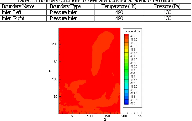
Table 3.2: Boundary conditions for oven at slit position adjacent to the bottom
Boundary Name Boundary Type Temperature (oK) Pressure (Pa)
Inlet_Left Pressure Inlet 490 130
Inlet_Right Pressure Inlet 490 130
Figure 3.2: Contours of Temperature Distribution for oven at slit position adjacent to the bottom
The results of CFD analysis of the oven by varying the position of Inlet slits adjacent to bottom of oven are obtained. With this geometry modification, the temperature contours obtained from the CFD analysis shows that the temperature
inside the oven ranges in between 488oK to 490 oK. which is the specified range of operation. From this it is concluded
that maintaining constant pressure on both the left and right inlet with slit inlets adjacent to the bottom, the uniform temperature can be achieved throughout the oven as shown in Figure 3.2
3.3. Effect of Using Perforated Inlet through Bottom of oven
The boundary conditions at which the analysis is carried out are as shown in the Table 3.3.
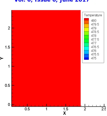
Table 3.3: Boundary conditions for oven using Perforated Inlet through Bottom
Boundary Name Boundary Type Temperature (oK) Pressure (Pa)
Inlet_Left Pressure Inlet 480 130
Figure 3.3: Contours of Temperature Distribution through Perforated Inlet
Figure 3.3 shows the CFD analysis for the oven with inlet through the perforated bottom. The temperature contours
shows uniform temperature distribution inside the oven. Temperature varies in very narrow range of 488 oK to 490 oK.
The distribution of temperature contours is as shown in Figure 3.3.
IV. CONCLUSION
The modeling and analysis of temperature distribution for gas fired convection oven at GUKSS Industries is carried out by using CFD analysis. From the results obtained it is concluded that:
1. At existing shape and boundary condition, there is problem of non uniform temperature distribution in the oven.
In particular, the area near bottom of oven is overheated due to the stagnation of hot inlet air. The geometry modification done to achieve uniform temperature distribution in the oven are having air entry to oven through inlet slit adjacent to bottom and using perforated inlet through bottom.
2. From the CFD analysis of modified geometry, the uniform temperature distribution is obtained throughout the
oven section. The range of temperature variation is limited to ± 2 oK. This results in considerable saving in both
power and time.
Nomenclature
qk Amount of heat transferred by conduction (W) k Thermal conductivity of the medium (W m-1 K-1) A Area through which the heat is transferred (m2)
dT
dx Temperature gradient normal to the area (k/m)
qc Amount of heat transferred by convection (W)
hc Average convection heat transfer coefficient
(W m-2 k-1)
ΔT Temperature Difference =(Ts−T∞) (K) g Acceleration due to gravity (m s-2)
β Coefficient of expansion (K-1) L Characteristic length (m)
ν Kinematic Viscosity (m2 s-1) Pr Prandtl Number (-)
Nu Nusselt Number (-)
Density (Kg m-3) Gr Grashof Number (-)
µ Dynamic Viscosity (Kg m-1 s-1)
Cp Specific Heat at Constant Pressure (J Kg-1 K-1) α Thermal Diffusivity (m2 s-1)
p Static pressure (N/m2)
τij Stress tensor (N m-2)
ρgi Gravitational body forces (N) Fi External body forces (N) h Sensible enthalpy (J)
τ Deviatoric stress ensor (N m-2)
Prt Turbulent Prandtl number for temperature. (-) µt Turbulent Viscosity (Kg m
-1
s-1)
REFERENCES
[1]. “Complete Guide To Powder Coatings”, World Leader In Powder Technology,/Issue1, Nov 1999.
[2]. “Understanding gas fired convection curing equipment for powder coating”, Rodger Talbert, Powder Coating, (Nov 1994),35-41.
[3]. “Two-dimensional CFD modeling and simulation of an industrial continuous bread baking oven”, Nantawan Therdthai et al,/ Journal of Food Engineering 60 (2003), 211–217.
[4]. “The Application of Computational Fluid Dynamics (CFD) And Oven Design Optimization In The British Bread-baking Industry”, Zinedine Khatir et al,/ 8th International Conference on CFD in Oil & Gas, Metallurgical and Process Industries SINTEF/NTNU, Trondheim Norway, 21-23 June 2011. [5]. “Computational Fluid Dynamic (CFD) Modeling and Validation of Temperature Distribution in the Infrared Oven”, Pumphruk Satit,/ School of Engineering and Physical Sciences, Heriot-Watt University, Edinburgh, UK.
[6]. “Numerical Investigation of the Temperature Distribution in an Industrial Oven”, Andrew Lee,/ University of Southern Queensland.
[7]. “Assessment of simplified thermal radiation models for engineering calculations in natural gas-fired furnace”, D.A. Kontogeorgos et al,/ International Journal of Heat and Mass Transfer 50 (2007), 5260–5268.
[8]. “Concept of Computational Fluid Dynamics (CFD) and its Applications in Food Processing Equipment Design”, Pragati Kaushal and Sharma HK,/ Journal of Food Process Technology, Volume 3 Issue 1,2012.