Cyclic loading of Exterior Beam - Column
Joint with Threaded Headed Reinforcement
Vaibhav R. Pawar1, Dr. Y.D.Patil2, Dr. H.S.Patil3
Research Scholar, Department of Applied Mechanics, S.V. National Institute ofTechnology, Surat, (GJ) India Assistance Professor, Department of Applied Mechanics, S.V. National Institute of Technology, Surat, (GJ) India.
Professor, Department of Applied Mechanics, S.V. National Institute of Technology, Surat,(Gujarat) India.
ABSTRACT: In Reinforced concrete structures, beam column joint is the most critical region in seismic prone areas. In structural concrete, the provisions for anchorage of straight bars and hooks occasionally present detailing problems due to the long development lengths and large bend diameters that are required, particularly when large diameter reinforcing bars are used. In many cases, the requirements for straight bar anchorage and lap splices cannot be provided within the available dimensions of elements. Hooked bars can be used to shorten anchorage length, but in many cases, the bend of the hook will not fit within the dimensions of a member or the hooks create congestion and make an element difficult to construct. Similarly, mechanical anchorage devices can be used to shorten lap splice lengths, but they frequently require special construction operations and careful attention to tolerances. Experimental work was conducted on exterior beam-column joint specimens with T-type mechanical anchorage. Welded and threaded headed reinforcement bars were used as T-type anchorage with short development length. The specimens were constructed and tested to assess the anchorage strength of headed bars under cyclic loading. The experimental results demonstrated that the specimen with T-type mechanical anchorage exhibited significant improvement in seismic performance load-displacement capacity, stiffness degradation, and also reduced congestion of reinforcement in joint core.
KEYWORDS:Anchorage Bar, Beam Column Joint, Bearing, Bond, Shear Stress. T-type anchorage I. INTRODUCTION
Fig.1 Beam column Joint fails due to shear failure in Kocaeli Earthquake
The failure of beam-column joints is the major contributor for the collapse of buildings due to earthquake excitation. It establishes the need for engineering approach to adopt efficient and economical methods to improve the joint performance. The need for study of earthquake effects on structures was realized when earthquakes occurred through the 1960s and 1970s causing irreparable damage and human loss. The design of joints was not given importance in the framed structures designed for gravity loads or gravity and routine live loads only. This causes severe problem in the event of an earthquake. Several studies led to the development of ASCE-ACI 352 Committee. Recommendations for the design of reinforced concrete beam-column joints (connections) in the year 1976. But there is a lot that has still not been understood about beam-column joint and research needs to highlight these issues.
II. SHEAR MECHANISM OF EXTERIOR BEMA COLUMN JOINT
For the design purposes, the horizontal component of the joint shear stress can be calculated from the combined effect of: (i) Diagonal strut mechanism, to consider the contribution of concrete in the joint; and (ii) Truss mechanism, to consider the contribution of the joint shear reinforcement. Figure 2 shows the forces in the beam bars, the joint mechanism and the force components in the joint for calculating the joint shear strength.
Fig. 2 Shear mechanism of exterior beam column joint (drawAutoCAD)
As shown in Figure 2, the equilibrium of forces acting above the horizontal plane passing through the centroidal axis of the exterior beam-column joint is as follows.
a) In terms of external forces: Vjh= Tb-Vc
Horizontal component of joint shear force, Vjh= Vch+Vsh
Where, Vch is the horizontal component of diagonal compression strut
Vch=Dc cos α=Cc+ΔTc-Vcol
Vsh=Horizontal joint shear force resisted by horizontal reinforcement by truss mechanism. Vsh= Ajhƒyt
Where,
Dc = Diagonal compression strut at angle “α” to horizontal axis of joint
Cc = Concrete compression force
ΔTc= Force in steel transmitted through bond to strut, over depth “c” of the flexural compression zone in the column Vcol= Shear force in column
Ajh= Horizontal joint reinforcement
fyt= Yield strength of joint reinforcement
Ahjcore= Horizontal c/s area of the joint
III. HEADED BAR
Headed bars, as shown in Fig. 3, provide an alternative to hooked bars and assist in alleviating steel congestion.Previous research on headed bars may be divided into two categories: performance of headed bars in realistic structural systems, and investigation of the mechanics of the headed bars under idealized conditions. Previous structural system studies include a number of beam-column joint investigations,where headed bars were used for longitudinal reinforcement, and slab-column joint investigations,where headed bars were used for shear reinforcement. The reliability and applicability of the headed bars were validated in these studies and, consequently, guidelines on the use of headed bars were introduced in ACI 352R-028 and ACI 421.1R-08. These guidelines provide guidance on general application of bars but do not provide direct estimates for the anchorage strength of headed bars.
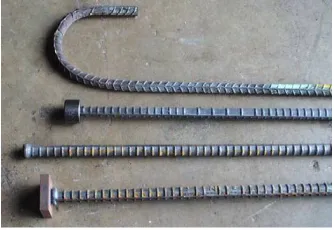
Fig. 3 Different headed bars and hooks bars
than 1.5 times an embedment length.14This case is rare due to the typical relative depths used for beams and columns as well as the higher strength and stiffness provided by most columns. A pullout mode of failure can occur if the net head area is less than 4 times the bar cross-sectional area. The pullout capacity of headed bars can be calculated using Section D.5.3 of ACI 318-08.15 When proper embedment and head geometry is used, a joint shear failure mode governs the response of the exterior beam-column joint. In this paper, the anchorage strength of headed bars under a joint shear failure mode is investigated through experiments and a new model to predict the strength is proposed.
Fig.4Failure modes joint due to headed bar IV. LITERATURE REVIEW
and exterior beam-column joint. Lee & Yu (2009) proposed extension of ACI design methods to cover the use of mechanical anchorage for eccentric beam-column joints. They reported that cyclic behaviour of exterior beam-column joints can be significantly improved by attaching double mechanical device on each beam bar within the joint. Bindhuet. al. (2008) in their experimental investigations validated with analytical studies carried out by finite element model indicate that additional inclined reinforcement bar improves the seismic performance of the exterior reinforced concrete beam-column joints. The use of headed bars has become increasingly popular for relatively large reinforced concrete (RC) structures that are exposed to extreme loads such as strong earthquakes or blasts, often providing an adequate solution to steel congestion (Chun et al 2007; Kang et al 2009, 2010). Sagbas et. al. (2011) in their FEA Computational analysis compared with experimental test results seismically and non-seismically designed joint detailed for the effect of shear deformations. Misir&Kahraman (2013) proposed a seismic strengthening technique for non-seismically detailed beam-column joints of existing reinforced concrete buildings using pre-fabricated SIFCON composite blocks.
V. TESTING PROGRAM
The specimens are divided into two groups, each group comprising of two specimens, with different anchorages. The specimen with T-type headed bar followed as per ACI-352 (2002). The specimen with conventional 90◦ bent hook
followed as per ACI-318 (2011) and the specimen with full anchorage followed as per Exterior beam-column joint study 1187,IS-456 (2000) is designated as shape detail. To relieve steel congestion within the joint while promoting proper bearing, use of a circular head with (Abrg/Ab) of approximately 4 is common. Prior experimental research 4,7,8
has shown that this head size is appropriate to ensure anchorage both in the elastic and inelastic deformation ranges, and a minimum ratio of (Abrg/Ab) = 4 is specified by ACI 318-08.The head size standard of (Abrg /Ab = 4) is relatively
easy to maintain in practice. The size of (Abrg/Ab) = 9 was originally recommended by the previous 1998 version of
ASTM A970,9 which is often impractical; for this reason, the specification that requires (Abrg/Ab) of at least 9, no
longer exists in ASTM A970-04
.
Fig.5 Different head size VI. MATERIAL PROPERTIES
Headed deformed bars with a bar diameter of 12 mm were used in this study. Three types of head geometries used for pullout tests. For reversed cyclic tests of the beam column joint, small circular heads were chosen based on the pullout test results. All headed bars and heads were made of steel with a specified yield stress fyof 415MPa. The specified concrete strength was 30 MPa. Headed and hooked bars used for seismic tests had similar actual yield strengths of 1.2fy
VII. EXPERIMENTAL SET UP
An experimental program was developed to investigate anchorage behavior of headed bars. Details of the specimens are presented in Fig.
The specimens were tested with the column in a vertical position, as shown in Fig. the force couples were monotonically increased until failure. The compressive force was applied to a bearing plate across the full length of the column. The tension force and compression force was applied through automatic double acting jack to the anchored headed and hooked bars. The specimens were designed in accordance with ACI 352R-02 except shape for the provisions regarding transverse reinforcement in the joint and the embedment length of a headed bar. Main test variables include embedment length and bar diameter, the size of head specimen is (Abrg/Ab=2.5) and the clear side
cover of 2.5db for a beam bar in an exterior joint is a common case, providing that the diameters of column bars and hoops are equal to 1db and 0.5db, respectively. Side-face blowout failure is precluded with the clear side cover of 2.5db. For comparison, two specimens with hooked bars were tested for each headed bar diameter examined. The embedment lengths for the hooked bar specimens were chosen to be equal to the longest and shortest embedment lengths of headed bars for each diameter. Shown the figure in reinforcement cage.
(c) (d)
Fig. 6(a) IS 13920:1993 [No Confinement], (b) IS 13920:1993 [with Confinement], (c) ACI-352 (2000) [No Confinement],(d) ACI-352 (2000) [with Confinement]
(a) (b)
-25 -20 -15 -10 -5 0 5 10 15 20 25
-40 -20 0 20 40
L
o
a
d
kN
Displacemnt mm
Specimen J2
-20 -10 0 10 20
-40 -20 0 20 40
L
o
a
d
kN
(c) (d)
Fig.7 Specimen details and hysteresis loop of exterior beam column joint(a) Hysteresis loop joint -1 (No Confinement),(b) Hysteresis loop Joint-2(with Confinement) , Hysteresis loop joint -1 (No Confinement), Hysteresis
loop Joint-2(with Confinement)
Fig.8 Peak Load Vs Displacement -20 -15 -10 -5 0 5 10 15 20 25
-35 -15 5 25
L o a d kN Dispalcement mm Specimen S2 -30 -20 -10 0 10 20 30
-50 0 50
p e a k L o a d Displacemnt S-1 S-2 J-1 J-2 Peak Load Vs Displacemnt
-20 -15 -10 -5 0 5 10 15 20
-40 -20 0 20 40
Table .1Pake load Vs. Displacement Specimen ID Yield specimen (mm) Δy Ultimate loading (kN) Pu Average ultimate Load kN(Pu) Ultimate displacement (mm) (Δu) Average ultimate Load kN(Δu) Average displacement ductility factor (mm) (u=Δu/Δy) Average stiffness kN/mm (K=Pu/Δy)
+ve -ve +ve -ve
J-1 13920 Bent-up bar (No Ring)
3.91 17.18 16.98 17.08 23.83 22.13 23.98 5.87 4.39
J-2 13920 Bent-up bar (with ring)
3.09 22.51 19.85 21.18 23.44 24.47 23.95 7.75 6.85
S-1 headed bar with steel fiber (No Ring)
10.99 17.97 17.97 17.97 23.7 23.7 23.7 2.15 2.15
S-2 headed bar with steel fiber (with ring)
6.636 19.64 13.62 16.63 28 28 28 4.22 4.22
VIII. RESULT AND DISCUSSION
The seismic tests were conducted to investigate the applicability of headed bars with threaded and welded type. The test data were assessed to examine the effect of the head size, shape and head attaching techniques on the anchorage behaviour under cyclic loads. The result from 1/3 scale seismic testing of a joint with headed bars were evaluated by compression with a companion specimen with hooked bars and by using the acceptance criteria of ACI 374.1-05. Based on the test result, the following conclusions were reached.
1) No brittle concrete brake out occurred for any headed bars in pullout, provided that the head size (Abrg/Ab) was
at least 2.5 and embedment depth was 11db.
2) The loading condition (monotonic Vs. repeated), head shape (circular Vs. Square), and head-attaching techniques (threading Vs. Welding) did not influences the anchorage behaviour substantially during testing. 3) The headed bar with large heads (Abrg/Ab=4.2) exhibited higher anchorage strengths than the heads bar with
small heads (Abrg/Ab=2.6 to 2.9)
REFERENCES
1. EN1992. (2004). Eurocode 2: Design of Concrete Structures, European Committee for Standardization (CEN), Brussels, Belgium.
2. EN1998-1. (2004). Eurocode 8: Design for Structures for Earthquake Resistance, Part 1: General Rules, Seismic Actions and Rules for Buildings, European Committee for Standardization (CEN), Brussels, Belgium.
3. Haldar, Putul, and Yogendra Singh. (2009). Seismic performance and vulnerability of Indian code designed RC frame buildings. ISET Journal of Earthquake Technology vol.46, pp29-45.
4. IS 456. (2000). Plain reinforced concrete-code of practice, Bureau of Indian Standards, New Delhi, India.
5. IS 1893-Part1. (2002). Part I: Criteria for earthquake resistant design of structures -General provisions and buildings, Bureau of Indian Standards, New Delhi, India.
6. IS 13920. (1993). Ductile detailing of reinforced concrete structures subjected to seismic forces-code of practice, Bureau of Indian Standards, New Delhi, India.
7. Khose, V.N., Y. Singh, and D.H. Lang. (2012). A Comparative Study of Selected Seismic Design Codes for RC Frame Buildings. To appear in Earthquake Spectra vol. 28,pp.1-4
8. Kumar, R., and Y. Singh. (2010). Stiffness of Reinforced Concrete Frame Members for Seismic Analysis. ACI Structural Journal vol. 107, pp607-615.
9. NZS 1170.5. (2004). Structural design actions Part 5: Earthquake actions-New Zealand, Standards New Zealand.
10. NZS 3101: Part 1. (1995). Concrete Structures Standard, Part 1 - The Design of Concrete Structures, Standards New Zealand, Wellington. 11. Kuang J. S. and Wong H. F., (2006) Effects of beam bar anchorage on beam–column joint behaviour. Proceedings of Institution of Civil
Engineers, Structures and Buildings, vol.159, No. 2, pp115–124.
12. Kuang J. S. and Ho Y. B.,(2007) Enhancing ductility of non-seismically designed reinforced concrete shear walls.vol. 27, pp 270-278 13. Proceedings of Institution of Civil Engineers, Structures and Buildings, vol.2007, 160, No. 3, pp139–149.
14. Kuang J. S. and Atanda A. I. (2005) Enhancing ductility of non-seismically designed reinforced concrete frame buildings. Proceedings of Institution of Civil Engineers, Structures and Buildings, vol.158, No. 4, pp253–265.
15. Atanda A. I. and KUANG J. S. Inherent ductility of non-seismically designed and detailed reinforced concrete shear wall-frame buildings. Transactions of the Hong Kong Institution of Engineers, 2005, 12, No. 3, 1–5.

![Fig. 6(a) IS 13920:1993 [No Confinement], (b) IS 13920:1993 [with Confinement], (c) ACI-352 (2000) [No Confinement],(d) ACI-352 (2000) [with Confinement]](https://thumb-us.123doks.com/thumbv2/123dok_us/1599944.1197623/7.595.105.516.176.430/fig-confinement-b-confinement-aci-confinement-aci-confinement.webp)