Throttle Control of Engine by Using PMDC
Motor and Drive
Nitin Ambrusi Kolekar, S. V. Shelar
ME Student, Department of Electrical Engineering ((Power Electronics and Drives),), All India Shri Shivaji Memorial Society’s , Institute of Information Technology Pune, Savitribai Phule Pune University, Pune, India
Professor, Department of Electrical Engineering ((Power Electronics and Drives),), All India Shri Shivaji Memorial Society’s, Institute of Information Technology Pune, Savitribai Phule Pune University, Pune, India
ABSTRACT: Engine testing is considered a very important aspect to the health and profitability of the automotive industry, Not only have customers been demanding quality engines, but government regulations have been becoming more strict, while costs keep spiraling higher. There are many types of tests that are performed on engines, and many methods for performing these tests. One such test is to run the engine as it will be used, under a variety of operating and environmental conditions, The purpose of the test is to determine how well the engine performs and whether the total engine and its subsystems maintain their specifications. Also, design flaws or problems can be discovered before production of a new engine gets too far down the road. In order to reduce the expense of running such tests and to ease the gathering of data, test cells are used. The engine is tested at different RPMs and various parameters like oil temprature ,coolant temprature, Oil pressure, Frictional torque, stepper position , Ignition advance ,Fueling time, Lambda value etc are measured and logged. To control the throttle in our experiment we are using PMDC motor. In a DC motor, an armature rotates inside a magnetic field. Basic working principle of DC motor is based on the fact that whenever a current carrying conductor is placed inside a magnetic field, there will be mechanical force experienced by that conductor. When permanent magnet is used to create magnetic field in a DC motor, the motor is referred as permanent magnet DC motor or PMDC motor. Have you ever uncovered any battery operated toy, if you did, you had obviously found a battery operated motor inside it. This battery operated motor is nothing but a permanent magnet DC motor or PMDC motorElectronic throttle control (ETC) system has worked its way to become a standard subsystem in most of the current automobiles as it has contributed much to the improvement of fuel economy, emissions, drivability and safety. Precision control of the subsystem, which consists of a dc motor driving a throttle plate, a pre-loaded return spring and a set of gear train to regulate airflow into the engine, seems rather straightforward and yet complex. The difficulties lie in the unknown system parameters, hard nonlinearity of the pre-loaded spring that pulls the throttle plate to its default position, and friction, among others. In this paper, we extend our previous results obtained for the modeling, unknown system parameters identification and control of a commercially available Bosch’s DV-E5 ETC system. Details of modeling and parameters identification based on laboratory experiments, data analysis, and knowledge of the system are provided. The parameters identification results were verified and validated by a real-time PID control implemented with an xPC Target. A nonlinear control design was then proposed utilizing the input-output feedback linearization approach and technique. In view of a recent massive auto recalls due to the controversial uncontrollable engine accelerations, the re-sults of this paper may inspire further research interest on the drive-by-wire technology.Our main aim to achieve the Throttle control of engine by using PMDC motor and Drive.
KEYWORDS: ETC System; System Identification; Nonlinear Control; Input-Output Feedback Linearization; xPC Target-Based Control System
I. INTRODUCTION
throttle control (ETC) system [1,2]. The sys-tem comprises of a throttle plate equipped with a pre- loaded spring and is driven by an electronic-controlled dc motor to regulate airflow in the intake manifold. In mod-ern vehicles, the engine control unit computes and maps the throttle plate’s angle to many entries such as accel-erator pedal position, engine speed, cruise control com-mand, and so forth in order to achieve optimal air-fuel mixtures in the combustion chambers, thereby maximiz-ing fuel economy and minimizing emissions. The ETC system, which responses to the prescribed reference from the engine control unit must operate with fast transient responses and precise control to regulate the throttle plate’s angular position [3,4]. Engine test cell consists of all the elements like ECU, dyno controller, throttle controller, field i/o, operator interface (HMI), frontend test cycle required for testing a four cylinder engine. Power train performance measurement is a statutory requirement by the government as well as vehicle manufacturer in order to ensure the consistency of the powertrain and adhere emission norms. Here in this project we are going to design and prepare a working model throttle control drive of engine with the help of PMDC motor and economical feedback of position and speed. Conventional FIP based diesel engine or petrol engine speed is controlled by a throttle lever. This lever is connected with the help of wire rope to a throttle actuator. The engine throttle has an opening from 0 to 100%. This in terms of angle comes to 0 to 90 deg. It needs control the position of the throttle lever with the help of PMDC motor and gearbox as per test cycle. The position will be tightly hold for time scheduled in the test cycle.
Developments of high performance motor drives are veryessential for industrial applications. A high performancemotor drive system must have good dynamic speed commandtracking and load regulating response. DC motors provideexcellent control of speed for acceleration and deceleration.The power supply of a DC motor connects directly to the fieldof the motor which allows for precise voltage control, whichis necessary for speed, position and torque controlapplications. DC drives, because of their simplicity, ease ofapplication, reliability and favourable cost have long been abackbone of industrial applications. DC drives are lesscomplex as compared to AC drives system . Speed andposition control of dc motor could be achieved usingmechanical or electrical techniques. In the past, speed andposition controls of dc drives are mostly mechanical,requiring large size hardware to implement. Advances in thearea of power electronics have brought a total revolution inthe speed and position control of dc drives . The use ofpower electronics for the control of electric machines offersnot only better performance caused by precise control and fastresponse, but also maintenance, and ease of implementation.In parallel with the advance in power electronic there havebeen great advances in microcontroller-based control systemsdue to the microcontroller flexibility and versatility. This isbecause all the control algorithms are implemented in the software . Now days, Induction motors, BrushlessD.C motors and Synchronous motors have gained widespreaduse in electric traction system. Even then, there is a persistenteffort towards making them behave like dc motors throughinnovative design and control techniques. Hence dc motorsare always a good option for advanced control algorithmbecause the theory of dc motor speed control is extendable toother types of motors as well . The motor speed can becontrolled by controlling armature voltage and armaturecurrent. It is obvious that speed control is possible by varying.· Flux per pole, Φ (Flux control).· Resistance Ra of armature circuit (Rheostat Control).· Applied voltage V (Voltage Control) .The above methods have some demerits like a large amount ofpower is wasted in the controller resistance. Hence, efficiencyis decreased. It needs expensive arrangement for dissipationof heat produced in the controller resistance. By these datathat are acquainted we can draw a conclusion that theseelectric and electromechanical methods are less adaptive soelectronic techniques are used for speed control. Thesemethods provide higher efficiency, greater reliability, quick response, higher efficiency . One such technique is PulseWidth Modulation. We apply this technique in our project soas to control the speed and position of the DC motor.
II. LITERATURE SURVEY
are used to controlthe speed of dc motor. For precise speed control of servosystem, closed-loop control is normally used. speed, which is sensed by analog sensing devices (e.g.,tachometer), is compared with the reference speed to generatethe error signal and to vary the armature voltage of the motor.
2.1Techniques for Speed and position control:
There are several controllers that can used to control the speed of the motor such as:
Armature voltage using Rheostat method for low power dc motors.
Use of conventional PID controllers.
Neural Network Controllers.
Phase-locked-loop control
Ac-dc buck-boost converter with only one switching device used for armature voltage control.
Fuzzy Logic Controller and etc 2.2Control Loops used in literatures:
A DC motor position control finds wide applications in servo systems, especially in aerospace, automotive and mechatronics applications. The position of a DC motor can be controlled by controlling the Armature Voltage or Field Voltage. The following are few of the simple methods of controlling a DC motor shaft position .
1. Open loop - without feedback of current position,method is ineffective and inaccurate in the presenceof load disturbance.
2. On-off controller - motor is turned on with maximumtorque till it reaches set point and switches off, thismay result in overshoots and oscillations .
3. Single directional control - reaches set point in a singledirection only, the angular position of a DC motor can also becontrolled by varying the torque generated by varying thearmature voltage or field voltage. In most digital applications,
4. PWM (Pulse Width Modulation) is generally used to control thespeed of the DC motor. It is relatively easier to generatepulses of varying duty cycles with a microcontroller ormicroprocessor. The pulses with varying duty cycle whenapplied to the armature will result in variable torqueproportional to the duty cycle. The control methodology usedin this project is to apply an average voltage proportional tothe error between actual position and the set point and reducethe average voltage as the current position approaches the setpoint. This kind of control is very effective in systems withhigh inertia as an inherent property, so that no control effort is reached.
2.3 The Controller Designing for Physical Model
Now must be design a controller for the physical model that is changed following of automotive throttle pedal. This controller is one of the ECU circuits. The parts of this controller have been demonstrated in figure 15. In the controller at first car driver pushes the pedal then the pedal signal is transmitted to ECU. The pedal signal is as reference signal. In the ECU throttle butterfly angle signal and reference signal have been compared in comparator portion and the error signal is produced. Then the error signal has been sent to DC motor driver. The driver portion acts by PWM2 method. The duty cycle of PWM signal is dependent to error signal. The higher error leads to higher duty cycle and vice versa. Also in this method, the butterfly direction is changed by getting of positive and negative voltage (as PWM). So two important portion of this controller is comparator and motor driver. In continues we will explain these two portions [7-9].
III. PROPOSED ARCHITECTURE
3.1 Test cycle concept
The THROTTLELEVER POSITION CONTROLLER under this project will be suitable for all types of fuel injectionsystems. Throttle actuator is operated in closed loop by takingposition feedback. Throttle zero position and range of operation canbe shifted electrically from the controller. Throttle Lever PositionController can be hooked up to Sequential Programmer or ComputerControlled Engine Performance Monitor.
3.2 Engine Throttle butterfly valve
Mechanical Throttle Bodies for Small Engines control air flow to the engine. They feature a butterfly valve in the throttle body which opens and closes the passage into the intake manifold to increase or decrease the volume of incoming air.
Mechanical Throttle Bodies offer a simpler alternative to electronic systems while maintaining excellent durability and reliability. They are mechanically linked to the accelerator and are constructed of aluminum or composite materials. Mechanical Throttle Bodies are also designed to provide the manufacturer with packaging flexibility.
Fig No 01 Engine Throttle butterfly valve 3.3 Interface Block Diagram
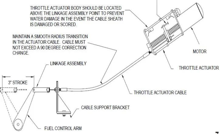
As show in the Block diagram the mechanical throttle of engine is connected with the wire rope to actuator linkage which is driven by the PMDC motor with gearbox. The DC sero motor will be controlled with the PMDC drive . The control strategy used is PWM . The driver ciricuit will generate the PWM signals for the Drive. The actual parameter entry and display will be done with help of arduino connected LCD and Keypad. Feedback loop is closed by Pot/encoder and RPM magnetic Pickup sensor.
3.4 Control Block Diagram:
Fig No 03 Control Block Diagram
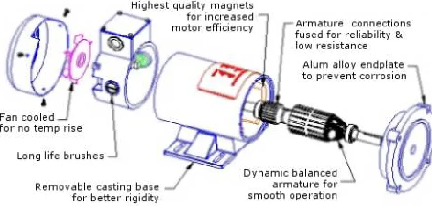
IV. MAJOR COMPONENTS 4.1 PMDC Motor.
4.2 Engine throttle wired (Mechanical ) connection
Fig No 05 Engine throttle wired (Mechanical ) connection
4.3 Cycle entry and display elements
A)% scale display(Angle display) Meter and feedback.
For feedback we can use encoder or pot for velocity control and RPM sensor from speed control .The feedback pot or encoder needs to be mounted on the final linkage of the controller. Sixty teeth gear wheel with sensing proximity will be used for this application.
B) Keypad for position entry.
Numerical keypad will be used for the entry. The cycles enteredcan have Step number , RPM set point and time allotted for the step .
C) Display for RPM
2X20 line lcd display will be used . This display can be used while setting up the cycle also . Also this display can be used for the displaying the parameters Step number , RPM set point and time allotted for the step .
V. PMDC MOTOR
5.1 Design and Operation:
Permanent magnet DC (PMDC) motors provide a comparatively simple and reliable DC drive solution in applications requiring high efficiency, high starting torque and a linear speed/torque curve. With the great strides made in ceramic and rare earth magnet materials, combined with electronic control technology, the PMDC motor is a cost-competitive solution for adjustable speed applications - delivering significant performance ina relatively compact size.The single design feature which distinguishes the permanent magnet DC motor from other DC motors is the replacement of the wound field with permanent magnets. It eliminates the need for separate field excitation and attendant electrical losses in the field windings.
5.2 Advantages:
Perhaps the most important advantage of PM field motors is their smaller overall size made possible by replacing the wound field with ceramic permanent magnets. ThePM motor’s ring and magnet assembly is considerably smaller in diameter than its wound field counterpart, providing substantial savings in both size and weight. See Fig. 1. And since the PMDC motor is not susceptible to armature reaction, the field strength remains constant. If we examine the field construction of the wound field DC motor versus the PMDC field motors, we can explainthe differences in armature reaction and corresponding differences in speed/torque characteristics of the two motor types. The armature magnetizing force in a wound field construction “sees” a very high permeability (low reluctance) iron path to follow. In the PM field design, this armature magnetizing force is resisted by the low permeability (high reluctance) path of the ceramic magnet, which tends to act as a very large air gap. The net result is that the armature cannot react with the field in a PMDC motor, thereby producing a linear speed / torque characteristic throughout its entire torque range.
PMDC motors offer benefits in a number of ways:
a) They produce relatively high torques at low speeds, enabling them to be used as substitutes for gear motors in many instances. PMDC motors operated at low speedsare especially useful where “backlash” and inherent mechanical “windup” of gearing in gearmotorscannotbe tolerated. It should be noted that if PMDC motors are continuously operated at high torque levels (above rated), they can generate serious overheating, or motor damage can result. b) The linear speed / torque curve of PMDC motors, coupled with their ability to be easily controlled electronically, make them ideal for adjustable speed and servo motor applications.
c) The linear output performance characteristics of PMDC motors also make it easier to mathematically predict their dynamic performance. See Fig. 3.The PMDC motor’s high starting torque capability can bea valuable asset in many “motor only” (non-gearmotor) applications as well as inertial load applications requiring high starting torque with less running torque. PMDC motors function well as torque motors for actuator drives and in other intermittent duty applications.The size reduction in PMDC motors is generally accomplished without any significant change in the temperature rise rating for a given horsepower. In fact, the electrical efficiency of the PMDC motor is very often 10% to15% higher due to the elimination of field copper losseswhich occur in wound field motors. PMDC motors canbe produced in TENV (totally enclosed non-ventilated)construction, eliminating the need for fans and providingmuch greater application flexibility.With their higher inherent efficiency, PMDC motors andgearmotors offer lower current drain for more efficient battery operation in portable applications. The permanent magnets also provide some self-braking (less shaft coast) when the power supply is removed. PMDC motors require only two leads (shunt-wound motors require four). The leads can be reversed by simply changing the polarity of the line connection. Dynamic braking is achieved by merely shunting the two leads after disconnecting them from the power source. Permanent magnet DC motors also provide similar performance characteristicsto shunt-wound DC motors when used with all common control methods (except field weakening).
5.3Design Considerations:
reversing requires current limiting, even at normal temperatures. The design of the motor’s power supply is also important.
PWM and SCR controls are designed to provide current
regulating and / or limiting features to protect the motor or gearmotor. The actual application parameters involved vary with each particular PMDC motor design, since the protection against demagnetization is part of the motor’s design and must be considered accordingly. It is best to consult the manufacturer if low temperature use or plug reversing is contemplated. As operating temperature increases, the residual or working flux of PMDC motors decreases at a moderate rate. This flux decrease is much like the decrease of field flux strength in wound field motors as copper resistance increases with temperature.
5.4Features
Because of their high starting torque characteristic, care must be exercised in applyingPMDC gearmotors. A PMDC gearmotor application should be carefully reviewed for any high inertial loads or high starting torque loads. These types of loads couldcause the motor to transmit excessive torque to the gearhead and produce output torque which exceeds itsdesign (rated) limits. PWM or SCR speed controls with built-in current limiting circuits, or overload slip clutches are sometimes employed to protect gearing used with PMDC motors.
• Continuous duty operation
• DC power supply (battery or speed controls)
• Reversibility at rest or during rotation with current limiting • Relatively constant and adjustable speed
• Starting torque 175% and up of rated torque
• High starting current, relative to full load running ent
VI. PMDC DRIVE
6.1flow chart for speed control
6.2 Flow chart for speed control continued
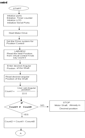
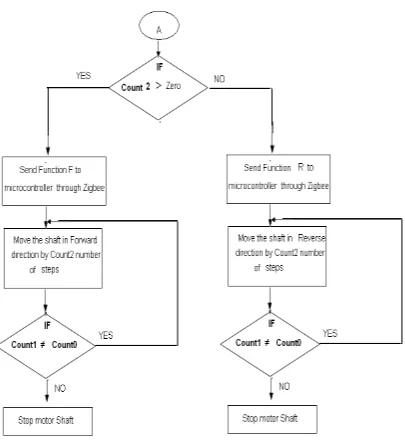
6.3 Flow Chart Poistion Control
Fig No 09 Flow Chart Poistion Control:
V. EXPERIMENTAL RESULTS
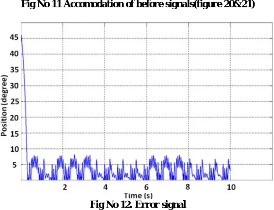
we accommodated the curves of figures 20 and 21 and in figure 23 the error signal between those signals has been demonstrated. The maximum errors in the error signal are 7 percents. These errors appear in limp home zone mostly
Fig No 10 . The reference signal
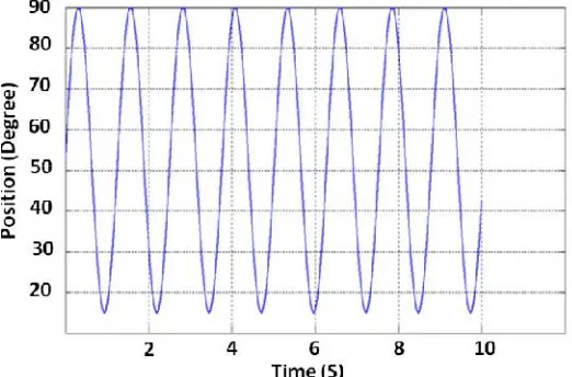
Fig No 11 Accomodation of before signals(figure 20&21)
Fig No 12. Error signal
The controller circuit consists of 2 portions. They are controller and driver portions. The controller portion can be Microcontroller or FPGA. In the structures that have many inputs and outputs, FPGA is useful but in this structure Microcontroller is enough the structure has been demonstrated in figure.
In this structure at first the Microcontroller receives the pedal and butterfly position signals then transmits proper comments to bipolar chopper portion. In the bipolar chopper portion the positive or negative PWM signals are produced
I=12/1.6=7.5A
Fig No 13. The controller structure by Microcontroller [6]
The H Bridge of this circuit consists of MOSFET IRF3205 and driver ICs IR2110. The freewheeling diodes (1N5818 Schottky diodes) have been used to protection of transistors from returned currents. The mechanism of this controller has been explained in flowchart of figure.
VI. CONCLUSION AND FUTURE WORK
Conclusion
From the consideration of all the above pints I conclude that In a DC motor, an armature rotates inside a magnetic field. Basic working principle of DC motor is based on the fact that whenever a current carrying conductor is placed inside a magnetic field, there will be mechanical force experienced by that conductor. Electronic throttle control (ETC) system has worked its way to become a standard subsystem in most of the current automobiles as it has contributed much to the improvement of fuel economy, emissions, drivability and safety. Precision control of the subsystem, which consists of a dc motor driving a throttle plate, a pre-loaded return spring and a set of gear train to regulate airflow into the engine, seems rather straightforward and yet complex. The difficulties lie in the unknown system parameters, hard nonlinearity of the pre-loaded spring that pulls the throttle plate to its default position, and friction, among others. In this paper, we extend our previous results obtained for the modeling, unknown system parameters identification and control of a commercially available Bosch’s DV-E5 ETC system. Details of modeling and parameters identification based on laboratory experiments, data analysis, and knowledge of the system are provided. The parameters identification results were verified and validated by a real-time PID control implemented with an xPC Target. A nonlinear control design was then proposed utilizing the input-output feedback linearization approach and technique. In view of a recent massive auto recalls due to the controversial uncontrollable engine accelerations, the re-sults of this paper may inspire further research interest on the drive-by-wire technology.Our main aim to achieve the Throttle control of engine by using PMDC motor and Drive.
Future Work-
a) Selection of motor.
b) Component selection& manufacturing of Drive c) Close loop technique and ckt development.
d) Command source and feedback display development e) Installation and wiring work
REFERENCES
[1] Jeffrey A. Cook, Fellow IEEE, Ilya V. Kolmanovsky, Senior Member IEEE ,”Control, Computing and Communications: Technologies for the Twenty-First Century Model T”, Proceedings of the IEEE | Vol. 95, No. 2, February 2007
[2] Jansri, A,” On practical control of electronic throttle body”, Industrial Electronics Society, IECON. 30th Annual Conference of IEEE,2004 [3] Guvenc, L.; Uygan, I. M. C.; Kahraman, K.; Karaahmetoglu, “Cooperative Adaptive Cruise Control Implementation of Team Mekar at the Grand Cooperative Driving Challenge”, Intelligent Transportation Systems, IEEE Transactions on Volume: 13, April 2012
[4] Toshihiro Aono and TakehikoKowatari, “Control Algorithm for Improving Engine Response Based on Air-Intake Model and Throttle-Response Model”, IEEE TRANSACTIONS ON INDUSTRIAL ELECTRONICS, VOL. 53, NO. 3, JUNE 2006
[5] Johan Gagner Rickard Bondesson,” Adaptive Realtime Control of a Nonlinear Throttle Unit “, master of science thesis in Automatic Control , Lund Institute of Technology,February 2000
[6] Xiaofang Yuan and Yaonan Wang , “A Novel Electronic-Throttle-Valve Controller Based on approximate Model Method “ , IEEE TRANSACTIONS ON INDUSTRIAL ELECTRONICS, VOL. 56, NO. 3, MARCH 2009
[7] Vasak, M, “Electronic throttle state estimation and hybrid theory based optimal control”, Industrial Electronics, IEEE International Symposium , May 2004
[8] Okuyama, Y, “PID control for nonlinear discretized systems “,SICE, Annual Conference Sept. 2007
[9] Liu, Jiang ,Study on electronic throttle system controller design , Vehicular Electronics and Safety (ICVES), IEEE International Conference ,July 2010
[10] QianWeikang , “Practical solution for automotive electronic throttle control based on FPGA”, Signal Processing, ICSP. 9th International Conference Oct. 2008
[11] Loh, R.N.K ,”Modeling, parameters identification, and control of an electronic throttle control (ETC) system”, Intelligent and Advanced Systems,.ICIAS . International Conference ,Nov. 2007
[12] Qiang Li, ”The study of PWM methods in permanent magnet brushless DC motor speed control system”, Electrical Machines and Systems,. ICEMS. International Conference , Oct. 2008
[13] Jianwen Shao,” An Improved Microcontroller-Based Sensorless Brushless DC (BLDC) Motor Drive for Automotive Applications”, IEEE TRANSACTIONS ON INDUSTRY APPLICATIONS, VOL. 42, NO. 5, SEPTEMBER/OCTOBER 2006
[14] IEEEE paper no.(05600865) efficiency enhancement of four-quadrant PMDC motor control trough combination of power electronics switchesAngelMarinov*, VencislavValchev** * Technical University, Varna, Bulgaria, e-mail: [email protected] ** Technical University, Varna,
Bulgaria, e-mail: [email protected].


![Fig No 13. The controller structure by Microcontroller [6]](https://thumb-us.123doks.com/thumbv2/123dok_us/1603272.1198194/14.595.137.467.191.389/fig-controller-structure-microcontroller.webp)