Jurnal Teknologi, 34(D) Jun 2001: 25–40 © Universiti Teknologi Malaysia
FORMAL SPECIFICATION OF A WALL-CLIMBING ROBOT USING Z – A CASE STUDY OF SMALL-SCALE EMBEDDED
HARD REAL-TIME SYSTEM
RADZIAH MOHAMAD1, DYG. NORHAYATI ABG. JAWAWI2, SAFAAI DERIS3 & ROSBI MAMAT4
Abstract. The task of checking whether a real-time system satisfies its timing and concurrency specifications is extremely important. One major area of research addressing software reliability aspect is called formal method, which attempts to prove the correctness of programs with respect to system specifications. Since, timing and concurrency properties can be very important in the operation of real-time systems, there is a need for applying formal methods to verify timing prop-erties. This paper investigates the process of building a formal specification of a small-scale embed-ded hard real-time systems using Z. It is expected that the formal specification presented in this paper can provide assistance in analysing design trade-offs early in the development process. It is also expected that this paper can act as the foundation for any upcoming formal methods related project especially for small-scale real-time systems project.
Key words: Software reliability, formal specification, Z, hard real-time, small-scale systems
Abstrak. Aktiviti menguji sama ada sistem masa nyata memenuhi spesifikasi masa dan keserempakan adalah sangat penting. Salah satu bidang penyelidikan dalam bidang keboleh-percayaan perisian ialah teknik formal yang cuba untuk membuktikan kesahihan sesuatu atur cara dengan spesifikasinya. Oleh kerana masa dan keserempakan merupakan aspek yang penting dalam sistem masa nyata, keperluan untuk menggunakan teknik formal sebagai teknik untuk mengesahkan aspek masa dan keserempakan ini adalah amat tinggi. Kertas kerja ini mengkaji proses membina spesifikasi formal untuk sistem masa nyata berskala kecil dengan menggunakan teknik Z. Spesifikasi formal yang dibangunkan di dalam kertas kerja ini diharap dapat membantu proses penganalisisan fasa reka bentuk di awal proses pembangunan sistem. Kertas kerja ini juga diharap dapat menjadi rujukan kepada projek-projek teknik formal yang akan datang terutamanya projek yang berkaitan dengan sistem masa nyata berskala kecil.
Kata kunci: Kebolehpercayaan perisian, spesifikasi formal, Z, masa nyata, sistem berskala kecil.
1.0 INTRODUCTION
The development of a wall climbing robot is currently requested strongly, on behalf of human operator, to perform dangerous operations on the surface of a wall. The
1,2&3Faculty of Computer Science and Information Systems, Universiti Teknologi Malaysia, 81310
Skudai, Johor Darul Ta’zim, Malaysia.
4 Faculty of Electrical Engineering, Universiti Teknologi Malaysia, 81310 Skudai, Johor Darul
potential applications for the robot are for operations such as fire fighting in high-rise buildings, wall surface cleaning or decorating and transporting along wall surfaces. A wall-climbing robot (WCR) is currently under development at Universiti Teknologi Malaysia. The WCR can be categorized as a small-scale embedded hard real-time system.
Real-time systems must produce their results within specified time intervals. The correctness of the system is therefore not only dependent on the logical results but also the time at which results are produced. According to the timing constraints, real-time systems can be classified as either hard real-time systems or soft real-time systems. In hard real-time systems, timing is critical where the lateness of the results is not permitted under any circumstances since late response are either useless or even dangerous. In soft real-time systems, timing correctness is important but not critical. Solving timing constraints and co-ordinating the communication between co-operating processes are therefore important in ensuring the software reliability.
Small-scale embedded hard real-time systems are becoming more sophisticated and usually offer many functions in one product. As a result, software development for small-scale embedded hard real-time systems are growing in scale and becoming very complex over the years. Furthermore, a real-time system is inherently concur-rent and multitasking since it has to react to and process numerous events simulta-neously. Thus, developing software for even small-scale embedded real-time sys-tems can be very difficult.
Due to the complexity and the nature of the control software for the WCR sys-tem, proving the correctness of the software requirements of the robot earlier is important so as to reduce the costs of requirement errors occur in later phases of software development life cycle. The purpose of this paper is to present the process of building a formal specification of a small-scale embedded hard real-time systems, in particular, the specification of control firmware for a four-legged WCR.
The organization of this paper is as follows: Section 2 will discuss the informal specification of the WCR. This will be followed by the formal specification of the WCR in the Section 3. Specifications for each component of WCR requirement were derived using Z. Section 4 will then conclude the paper.
2.0 INFORMAL SPECIFICATION OF THE WALL-CLIMBING ROBOT FIRMWARE
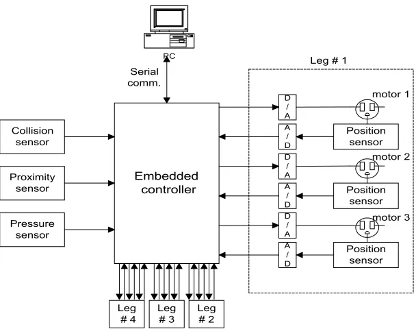
The main function of the embedded digital controller is to move the four legs of the robot with a predefined sequence during climbing operation. The block diagram of the embedded controller for the wall-climbing robot is shown in Figure 1.
(i) sensors monitoring (ii) motor control
(iii) serial communication with external PC
The embedded controller monitors its environment using some sensors i.e. colli-sion sensors, proximity sensors and pressure sensors. Collicolli-sion sensors send signal to controller when the sensor collides any obstacles. Obstacle sensors detect the presence of a distance obstacles. This environment must be monitored typically every 500 milliseconds to detect the presence of obstacles using the collision and the obstacle sensors during the forward and reverse movement of the robot. Three position sensors in the form of rotary potentiometers at each leg measure the joint angles of the leg during the leg movement. Position sensors read the current position of the legs joint angle. The highest priority task in the controller software is the motor control task with a cycle of 50 milliseconds. This is to ensure the correct movement of the legs.
3.0 FORMAL SPECIFICATION OF THE WALL-CLIMBING ROBOT FIRMWARE
Formal methods have been studied for a long time for the development of software. Formal methods have been thought of as having great promise for the development
Embedded controller D / A A / D Position sensor D / A A / D Position sensor D / A A / D Position sensor Leg # 1
Leg # 2 Leg # 4 Leg # 3 PC Serial comm. Proximity sensor Collision sensor Pressure sensor motor 1 motor 2 motor 3
of real-time systems [1]. The term formal method refers to the use of the techniques from logic and discrete mathematics in the specification, design and construction of computer systems and software [2]. The essence of the formal methods is a formal specification. Since timing and concurrency properties are very important in the operation of real-time systems, there is a need for applying formal methods to specify timing properties. In order to increase the reliability of the software developed, developing specification that can be verified during an early stage of the develop-ment is hence needed.
The formal specification notation Z is one of the most popular and widely used notations for the formal specifications and development of software and hardware systems [3]. Z is a formal specification language based on a standard set theory and uses a mathematical notation. The specification is divided into a number of units or blocks [4]:
(a) Basic type definition defining the values which constants and variables may take.
(b) Global constant and variable definition within the system and any con-straints on them.
(c) Schemas defining the state and operations of the system.
Traditionally, Z is widely perceived as being unsuitable to specify concurrent and temporal behaviour of the system [3]. Recently however, there has been consider-able interest in applying Z to specify a concurrent and temporal behaviour of the system. Much of this work has concentrated on integrating Z with formalisms better suited to specifying concurrent and temporal behaviour, such as Petri Nets [5], Tem-poral Logic [3], CSP [6] and CCS [6]. However, a main disadvantage shared by all these approaches is the difficulty of reconciling the semantics of the separate nota-tions, resulting in problems of compatibility with the standardized definition of Z and existing Z tools for proof and type checking. Moreover, techniques for reason-ing with the resultant hybrid notations generally makes poor use of the excellent proof system offered by Z. This paper shows a somewhat different approach to specifying concurrent and temporal behaviour of the system in Z. Rather than inte-grating Z with yet another formalism, modifications are made to the Z specification based on the Z’s generic model proposed by [7]. Next subsection introduces the formal specification of the WCR using Z.
3.1 The Embedded Robot's Control Software
The following types are used to describe state information of sensors. Collision_Sensor denotes the state of a collision sensor; On denotes the sensor collides any obstacles, while Off denotes the sensor does not collide any obstacles. Obstacle_Sensor denotes the state of an obstacle sensor; On denotes the sensor de-tects the presence of a distance obstacle, while Off denotes the normal state (does not detect the presence of obstacle). Pressure_Pad denotes the state of the suction pads of the robot leg; Yes denotes enough pressure is maintained in the suction pads, while No denotes the pressure maintained in the suction pads is not enough. PressureActivate is used to describe whether an indicator for specific button on a pressure pumps is activated (active) or deactivated (passive). Pccommand denotes the command from the PC to the controller; Start_Move denotes the command to the controller to trigger the robot to start moving, while Stop denotes the stop moving command. RobotState refers to the state of the robot at time t; Moving denotes the robot's leg or body is moving, while Stop_Move denotes the leg or body is stop from moving; Idle denotes the leg or body is not moving.
The abstract system’s state of the robot controller is specified by the schema RobotController. There is one major system variable mode of type Modes representing the current operational mode. The other system variables can directly be derived from the system specification.
During initialization, the controller is in the Idle mode and the Robot is in the Idle state.
The following schemas define predicates on the controller’s state that are used to model the interdependencies between the dynamic behavior and the current controller’s state.
Informally, the specification above asserts that when the leg’s pressure is enough, the pad variable is set to Yes. In the presence of a distance obstacle, the obstacle sensor indicator will be triggered to On and the mode will be changed to Waiting PC command as to whether to keep on moving or stop from moving. Whenever the collision sensor collides with any obstacles, the collision sensor indicator will be triggered to On. The next four specifications assert the relevant mode of the control-ler as per operation.
3.2 Pressure Sensor Operation
The following schema (PressureSensor) describes the operation of the pressure sensor. Here, the D convention is used to include the before and after components of the state schema PressureState, PressureLeg and PressureMode. If a pressure pump button indicator of suction pad, pad?, is passive, it will be activated only if the suction pad has no enough pressure (pad? = No). In the former case, this will be as a pre-selection, so that the pressure pump will automatically be activated as soon as the suction pad has no enough pressure. If the pressure pump is activated and the suction pad has enough pressure, pumping the pressure into the suction pad has no effect since when the suction pad has no enough pressure, the pressure pump will automatically be activated in any case.
3.3 Collision Sensor operation
Collision sensor sends signal to the controller when the sensor collides any ob-stacles. Schema CollideState models the state of Moving, Stop_Move of the robot's leg or body defined for each state of the collision sensor.
3.4 Obstacle sensor operation
The obstacle sensor sends signal to a controller when it detects the presence of a distance obstacle. Schema ObstacleState models the state of Moving, Stop_Move of the robot’s leg or body defined for each state of the obstacle sensor.
3.5 Position Sensor operation
Position sensor reads the current position of legs and body of the robot. The robot has four legs and a body. They are formally defined by the free type Leg and Body.
Set RobotPos combines leg identifiers of the robot of type natural numbers. Set Robotpos1 combines body identifier of the robot of type natural numbers.
Schema PosState models the current position defined for each leg and body of the robot and the target position defined for each leg and body of the robot.
3.6 Motor Control operation
The motor receives the computation of control signal (the error computation be-tween the target position and the current position of each legs and body of the robot) from a controller to ensure the correct movement of each leg and body. Schema MotorControl describes the operation of the motor control with the output of a computation error, error! sent to the motor control.
3.7 Serial communication with external PC
3.8 Temporal specification of the WCR
The temporal specification of the WCR is based on the improved Z reci pe by [7]. The next specifications define states which specify all the operations which interact. This process is called promotion. SendCol lisionSignal for example, specifies all the individual operations which interact in sending the collision signal to the controller.
The operations can now be used to add timing constraints to the operation of the controller.
milliseconds but no more than 20 milliseconds, from a motor control at least 50 milliseconds but no more than 100 milliseconds.
3.9 Concurrency Specification
A dynamic specification describes the concurrent behavior in terms of the allowable sequences of behaviors that result from the execution of its operations. It is assumed that operations are atomic, i.e. they occur instantaneously. Concurrency is modeled by the non-deterministic interleaving of atomic operations. As with the temporal consideration, the approach used here is based on the improved reci pe by [7].
The first step in modeling the concurrency behavior is to construct a next-state schema. This is the disjunction of the system’s operations. It represents the fact that an atomic step in the controller’s behavior may be caused by any one of its opera-tions. The next-state schema for the controller is the disjunction of SendCollisionSignal, SendObstacleSignal, SendPressureStatus, SendPositionStatus and SendToMotorControl.
The controller’s initial state set and next-state relation must be obtained from Initialize and ControlNS. To do this, schema binding (q) is used to project out the relevant state components before direct substitution into validcompt [7]:
Any behavior that satisfies t will be a valid behavior of the controller.
3.10 The Robot Behaviour
or stop from moving. So, as when the formal method is concerned, it is assumed that the sequence consideration of the leg’s and body’s movement falls into another field of study.
The robot has four independent legs and a body. A generic leg’s state and body’s state are first specified:
The leg or the body is either at the state of moving or stop from moving. Initially, the leg and body is at the state of Idle.
The robot has four legs and a body called leg1, leg2, leg3, leg4 and body and have ten discrete movements.
Each of the generic leg and body operations are then promoted to operations of the robot legs and body:
The specification of the system needs an overall state so the operations which interact can be specified. In this project, the total state is called WallClimbing. There-fore, the WallClimbing is a conjunction of Robot schema and RobotController schema.
FinalPosLeg1 denotes the final position of the leg 1 after correcting the error between the current position and the target position in which if there is an error, the leg or the body will be moved to the targeted position. The error computation will then be sent to the motor control. The same explanation applies to FinalPosLeg2, FinalPosLeg3, FinalPosLeg4 and FinalPosBody.
4.0 CONCLUSION
The main idea behind this paper is that in order to increase the readability and correctness of the computer software, in particular the hard real-time systems, it is desirable to separate the often contradictory aims of writing a clear and understand-able program with one which is efficient. Formal specifications can greatly help in providing a rigorous and precise framework within which the specification can be written. This paper has shown that Z specification can be developed for the small-scale embedded hard real-time system. A case study, the embedded controller of the four-legged WCR was used to illustrate the approach.
ACKNOWLEDGEMENT
The authors would like to thank UTM Mobile Robot Research Group (MRRG) for their cooperation in defining the wall-climbing robot requirement specification.
REFERENCES
[1] Joseph, M. 1997. Real-time systems and Formal Methods, In Real-time systems: Specification, Verification & Analysis edited by Mathai Joseph, Prentice Hall.
[2] NASA, 1997. “Formal Methods Specification and Analysis Guidebook for the Verification of Software and Computer Systems”, Vol. II: A Practitioner’s Companion, 1997.
[3] Duke, R. and G. Smith. 1989. Temporal Logic and Z Specifications. Australian Computer Journal, 21(2): 62 – 69, May 1989.
[4] Spivey, J. M. 1992. The Z Notation: A Reference Manual. Prentice Hall, Second Edition, 1992. [5] Eva, A. S. 1994. Visualising Concurrent Z Specification. Z User Workshop, Cambridge 1994, Workshops
in Computing, Springer-Verlag, 1994.
[6] Coombes, A. and J. Mc Dermid. 1993. Specifying temporal requirements for distributed real-time sys-tems in Z. Software Engineering Journal. 8(5): 273 – 283, September 1993.
[7] Evans A. S. 1994. Specifying & verifying concurrent systems using Z in M. Naftalin, T. Denvir, and M. Bertran, editors, FME’94: Industrial Benefit of Formal Methods. Formal Methods Europe, Springer-Verlag volume 873 of LNCS, pp 366-400.