Electronic Theses and Dissertations Theses, Dissertations, and Major Papers
1-1-1980
Analytical and experimental studies on the rigidities of
Analytical and experimental studies on the rigidities of
orthogonally and non-orthogonally rib-stiffened concrete slabs.
orthogonally and non-orthogonally rib-stiffened concrete slabs.
Satish Kumar Bali
University of Windsor
Follow this and additional works at: https://scholar.uwindsor.ca/etd
Recommended Citation Recommended Citation
Bali, Satish Kumar, "Analytical and experimental studies on the rigidities of orthogonally and non-orthogonally rib-stiffened concrete slabs." (1980). Electronic Theses and Dissertations. 6747. https://scholar.uwindsor.ca/etd/6747
NQH-QRTHOGO NALLY RIB-3TIPPSNED CONCRETE SLABS
by
Satish ICumar Bali
A Thesis
submitted to the Faculty of.' Graduate Studies through the Department of
Civil Engineering 'in Partial Fulfillment of the requirements for the degree
of Master of Applied Science at The University of Windsor
Windsor, Ontario, Canada 1980
INFO RM ATIO N TO USERS
The quality of this reproduction is dependent upon the quality of the copy submitted. Broken or indistinct print, colored or poor quality illustrations and photographs, print bleed-through, substandard margins, and improper alignment can adversely affect reproduction.
In the unlikely event that the author did not send a complete manuscript and there are missing pages, these will be noted. Also, if unauthorized copyright material had to be removed, a note will indicate the deletion.
UMI Microform E C 5 4 7 2 4 Copyright 2010 by ProQuest LLC
All rights reserved. This microform edition is protected against unauthorized copying under Title 17, United States Code.
ProQuest LLC
789 East Eisenhower Parkway P.O. Box 1346
^ Satisli Kumar Bali. 1980
7 4 1 1 4 3
« « *
In thi3 study, analytical expressions for
the anisotropic rigidities ox" reinforced, concrete
orthogonally rib stiffened, slab, structures- are
presented. These expressions are valid for botlx tire
precracking and post-cracking stages of concrete and
are, therefore, applicable to reinforced as well as
prestressed concrete structures. The existing exper
imental method for determining the rigidity constants
of orthogonally stiffened plates is modified tro properly
account for the coupling rigidities of the slab struc
ture. The method, utilizes the fact that pure bending
and twisting moments: can be expressed in terms of the
curvature, and twist of the surface, respectively.
Flexural and twisting tests on several reinforced con
crete orthogonally rib stiffened structures were con
ducted. The experimental results verify and substant
iate the* analytical expressions for both the precrack
ing and post-cracking rigidities of the structure and
are also compared with the existing theories.
Theoretical, expressions are also given to
calculate the elastic rigidity constants of
non-orthogonally rib stiffened reinforced concrete slab,
structures. These formulae are also valid for the
elastic flexural and torsional rigidities of
orthog-Iv
of non-orthogonally; stiffened slabs can be determined
by applying pare bending and twisting moments to the
test specimens. The experimental procedure and the
necessary precautions that must be taken to help insure
accurate results are discussed. The use of realistic
estimates, for the anisotropic rigidity constants of
rib stiffened reinforced concrete slab structures will,
The author wishes to express, his sincere
gratitude to Dr., JJ3* Kennedy, Professor of Civil
Engineering- at the Uhivarsity of Windsor, far his
guidance, encouragement: and valuable suggestions
throughout the development, o f this thesis.
Many thanks' are due to Mr. G, Michalesuk and
Mr.. P. Feimer for their assistance in the experimental
work.
The financial assistance provided by the
National Research Council of Canada under grant Ho.
A- 1896 is greatly appreciated*
vi
ABSTRACT:... *... iv
ACKNOWLEDGEMENTS... vi
TABLE OP CONTENTS... vii
LIST OP ABBREVIATIONS... ix
CHAPTER I INTRODUCTION - -... 1
1.1 General... 1
1.2 Object;... 1
1.3 . Scope... 2
CHAPTER II HISTORICAL REVIEW... 3
CHAPTER III THEORETICAL; FORMULATION. ... 8
3.1 General Concept... 8
3.2 Assumptions... *... 9
3.3 Governing Differential Equation. 10 3.4 Rigidities of Orthogonally Rib Stiffened Uncracked Sections.... 11
3.4.1 Flexural Rigidities ... 11
3.4.2 Torsional Rigidity... 13
3.5 Rigidities of Orthogonally Rib Stiffened Cracked Sections... 16
3.5.1 Flexural. Rigidities... 16
3-5.2 , Torsional Rigidity... 18
3.6; Rigidities of Non-Orthogonally Rib: Stiffened Slabs... 19
CHAPTER IV MATHEMATICAL FORMULATION' FOR THE. EXPERIMENTAL STUDIES .... 24
4.1 Rigidities of Orthogonally Rib Stiffened Slabs... 24
Rite Stiffened Slates ... 2 7
CHAPTER V EXPERIMENTAL. INVESTIGATIONS 38
5;.l Saope of the Experimental
Progamme... 38
5..2 Materials,... 38
5-2.1 Concrete... 3S-5.2.2 Reinforcement... 39
5.3 Description of the Specimens. .... 39
5.4 Casting of the Specimens... .. 41
5.5 Instrumentation... 42
5.6 Experimental Set-Up and: Test Procedure... *. 43
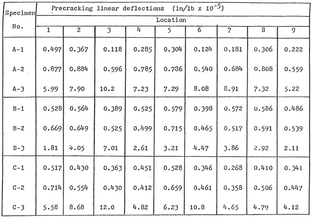
5.7. Experimental Results... 44
CHAPTER VI DISCUSSION OP RESULTS... 48
6j.l Flexural and Torsional Rigid-' ities ... 46
6.2 Sources of Error... 52
CHAPTER VII CONCLUSIONS AND RECOMMEND- . ATIONS ... 54
7.1 Conclusions... 54
7*2 Recommendations For Future Research... '... 55
BIBLIOGRAPHY... 57
TABLES... *... 61
FIGURES... 67
COMPUTER PROGRAM... ... ... *. 95
VITA AUCTORIS... 102
A_ (a!) Area of tension steel in
long-s s
itudinal (transverse) rib
A Area of tension steel in skew rib
sv
b (b ) Width of longitudinal (transverse)
3c y
rib
b Widtb of tbe skew rib
v
D Flexural rigidity of tbe flange
plate witb. respect to its middle
plane
D^, (Dy) Flexural rigidity of tbe orthog
onally rib stiffened slab in tbe
x- (y-) direction.
D (D ) Torsional rigidities of tbe
ortb-xy yx.
ogonally rib stiffened slab
D u , D1 2 » Dl6 Rigidity constants of tbe
cross-D 22i cross-D 26» ® 6 6 section of tbe non-orthogonally
rib stiffened slabs
d (d ) Depth of the- longitudinal
(trans-x. y
verse) rib
d*(d") Concrete cover to tbe centre of
longitudinal (transverse) rein
forcement
d^ Depth of tbe skew rib'
d* Concrete cover to tbe centre of
v
ax* ey' ev Depth of neutral plane of the uncrac
ked section from extreme compression
fibre for bending in the x-, y- and
v- direction respectively
f * 28 day compressive strength of
concrete (psi)
G Shear modulus of concrete
h Thickness of flange plate
J“ Torsional constant:
K Torsional parameter
kflV , k^y, k ^ Depth of neutral plane of the crac
ked section' from extreme compression
fibre .for bendiug in the x-, y- and
v- direction respectively
M , M , M Bending' and torsional moments
x. y xy
associated with the x- and
y-ax:«s
it Modular ratio
q.(x,y) Intensity of lateral load on
the stiffened slab.
S (s ) Spaaing of the longitudinal
x. y
(transverse) ribs
S Spacing of the skew ribs
v
w . w « w
,MUf ,YV’t UV
surface associated with, the
x-and y~ axes
Curvatures and twist of. the sur
face associated with the u- and.
v- axes
Curvatures, associated with
r-and t- axes
Rectangular co-ordinates system
Oblique co-ordinate system
Angle of inclination, of the skew
ribs ("V- axis) to the y- axis
Poisson* s ratio of concrete w ,rr’ w ,tt
x, y, z
1.1 General
Thin plates stiffened by a system of orthogonal
or non-orthogonal ribs have found wide application
for aircraft, bridge, building and ship bottom structures
as well as ini many other branches of contemporary
structural engineering. These stiffened elements,
representing a relatively small part of the total weight
of the structure, substantially influence its strength,
stiffness and stability leading to economy and other
advantages. Studies of orthogonally and non-orthogonally
stiffened slabs have been of particular interest and
practical importance in. bridge structures constructed
for reasons of economy and structural efficiency.
It becomes essential to use realistic estimates of
the rigidity constants of the structure in order to
predict accurately the behaviour of such construction
to an applied load.
1„2 Obneat
The object of this investigation is to develop
theoretical expressions for determining flexural and
torsional rigidities of orthogonally and
non-orthogon-ally rib stiffened reinforced concrete slab structures*
Since concrete is a non-homo gene ous material, it is
l
conducting experimental studies,. Thus, the overall
objectives of this study are:
a) To develop simple and rational expressions
tc predict flexual and torsional rigidities
of anisotropic, concrete slabs,
b.) To develop mathematical expressions to calcu
late the anisotropic rigidities of. reinforced
concrete rib-stiffened, slabs by means of
laboratory tests,
c) To substantiate and verify the analytical
expressions by experimental results from the
tests on orthogonally rib stiffened slabs only,
since the analytical expressions for
non-orthogonally rib stiffened slabs are also
applicable for orthogonally rib-stiffened
slabs.
1.3 Scone
Simple expressions are proposed for the
precracking and postcracking rigidities of orthogonally
rib-stiffened reinforced concrete slabs. The analysis
is verified by experimental results from bending and
twisting tests on. reinforced concrete waffle-slab
elements. Analytical expressions and experimental
procedure are also developed for the determination
rib-HISTORICAL REVIEW
Historically, the development of stiffened
structural elements is ons of slow growth. In the
early stages of development, man probably learned of
the existence of such forms from nature. Sea shells,
trees, leaves, vegetables - all of these are, in fact,
stiffened structures. The wide use of stiffened struc
tural form, in engineering began in the nineteenth
century, mainly with the application o£ steel plates
£or hulls of ships and with the development o£ steel
bridges and aircraft structures.
The study o£ elastic constants of. plates by
bending and twisting testa began in. 1927 when Bergatrasser
(4 ) used a procedure suggested by Nadai for experimentally
applying pure bending and twisting moments on a plate of
constant thickness. For applying the bending moments,
he used a rectangular plate- supporting it- at three
points and loading it at three other points.. A square
plate, was used for applying a twisting moment that was
supported, on. two diagonally opposite corners and loaded
on. the other two corners. BSergstrasser assumed, that
the shape of the deflected, surface for an isotropic
plate due to a pure bending moment (Mx ) could be
expressed as
where, x and. y are the rectangular co-ordinates.
Thielemann
(34)
and HearmPm and Adams(14)
usedessentially the same procedure. The principal difference
between these various investigators is in the manner
in which they measured the displacements caused b y
the applied bending and twisting moments or i n the
equations used to determine the elastic constants.
Bergstrasser
(4)
and Hearmon and Adams.(14)
measuredtheir displacements by placing a measuring device on
the deflected plate and thus calculated relative dis
placements. Thielemann
(34)
and Rearmon and Adams(14)
assumed that, the deflected shape for a "specially
orthotropic" plate (principal axes; parallel to the
sides of the plate) had the form
w = dEjj/h3
(Slx
x2 + S12 y )
(1.2.2)
where S-^ and S12 are the elastic constants which
c a m be expressed as l/Ex and - M^y/E^ , respectively.
3?or the case of a homogeneous isotropic plate, Ex ^ E
and M .. Roth equations (1.2.1) and (1.2.2)
xy
described a hyperbolio-paraboloid surfhce,
Witt, Hoppmanm and Buxbaum
(38)
have given, thetheoretical basis and an. experimental method for
determining the anisotropic elastic constants of
boundary. They measured the displacements relative
to a fixed plane and described the shape of. the- de
flected surface of the plate by
w = SM^/hP (S±i2C2 + S ^ y 2) + Ax + By + C (1.2.3)
where and S^.. are the. elastic constants. She
constants A,B and C were determined from the boundary
conditions in. which w = 0 at the three support points.
In 1956, Huffington (18) investigated theoretically
and experimentally the method for the determination
of rigidities for metallic rib-reinforced deck structures.
It was applied to the case of. equally spaced stiffeners,
of rectangular cross-section, and symmetrically placed
with respect to its middle, plane.
Beckett et al (3) presented a curvature, method
for the experimental determination of elastic constants
of. orthogonally stiffened plates. Ihe method utilized
the; fact that pure bending and twisting moments can
ha expressed in: terms of the curvature and twist of a
surface, respectively.
In 1968, Jackson (20) proposed a method to.
estimate the torsional rigidities of concrete bridge
decks using membrane analogy and accounting for the
junction effect, The.- effect of the continuity of the
slab: o n the flange plate was not accounted for. CJardenas
stiffnesses; of isotropically and. nom-i so tropically
reinforced, concrete: plates. Results indicated that the
stiffness of' such, plates was related quantitatively
to the. relative orientatiom of the reinforcement
with respect to the applied forces, the combinations
of the applied forces and the amounts of the reinforce
ment : . ±tl the two orthogonal directions. Kennedy and
Gupta (22) used the elastic constants of the equivalent
structure which- closely resembled the twisting and
bending behaviour of an orthogonally stiffened plate
structure to analyse the original structure by means
of the orthotropic plate theory.
Gusens et al (19) presented an elastic analysis
for plates reinforced with an.orthogonal system of
rectangular ribs, which enables the determination! of
rigidities of the structure in flexure and torsion.
The analysis did not account for the stiffening effect
of the orthogonal ribs oni the torsional rigidity of
the. flange plate; also the method is not applicable
for reinforced concrete bridge decks where some crack
ing is expected or for structures with relatively
thick flange plates. Little information. is available
as to how these rigidities might be assessed for the
cracked sections of a concrete structure. Desayi
concrete slabs up to the yield load.
In 1972, tbe Concrete. Reinforcing Steel Institute
(8 ) recommended tbat tbe average gross moment- of
inertia be used for two way joist and waffle slabs.
Lampert (26) derived theoretical expressions for tbe
post-cracking stiffness of rectangular reinforced
concrete beams in torsion: and bending using a space
truss model.. lofriet and McNeice (19) used empirical
bilinear moment curvature relationships- -to incorporate
the influence of cracking in tbe finite element analysis
of slab structures. Recently,, Clark and White (6 )
carried out testa to determine tbe torsional stiffness
of' flexurally cracked slab elements.
THEORETICAL FORMULATION
3.1 General Concent
In this. chapter, the analytical method, to
obtain, flexural and torsional rigidities of orthogonally
and non-orthogonally stiffened plates is developed,.
I f a homogeneous material has three mutually perpen
dicular planes of symmetry with. respect to its elastic
propertias., it is. called orthotropic, i.e. materials
which are orthogonally anisotropic, for instance,
.
two-way reinforced, concrete slabs are intrinsically
anisotropic. Other materials with natural anisotropy
are plywood, fiber-reinforced plastics and. wood. In
certain cases, structural anisotropy is introduced by
means of corrugations or ribs such as decks of steel
bridges, corrugated plates, composite beam grid frame
works, concrete slabs reinforced with closely spaced
ribs, etc. These structures can be analyzed using
orthotropic plate theory which assumes that the
ortho-tropy of the structure may be replaced by the orthoortho-tropy
of the constituent material. Although the actual struc
tural behaviour of a stiffened plate cannot be entirely
replaced by that of an equivalent orthotropic plate,
previous theoretical and experimental investigations
Ini dealing herein with, orthotropic concrete
atructurea, it ia aaaumed that orthotropy ia a reault
of geometry and not of material. Except for the
aaaumptiona made with, reapeat. to the ribatiffened conatruction,
-the aaaumptiona for orthotropic platea are baaed on. -the
aame aaaumptiona uaed in the analyaia of iaotropic platea,
and they are outlined, below.
a) The material of the plate ia considered to be
c.ontinuou3 and homogene oua, by tranaforming
the ateel area into an equivalent area of
concrete.
b) The plate thickneaa ia uniform and araall compared
with other dimenaiona of. the plate. Thua, the
ahearing stre3sea and atreaaea normal to the
pla-ne of aymmetry are amall and can be pla-neglected.
c) The deflectiona of the loaded plate are amall
in compariaon to Ita thickneaa, ao that membrane
atreaaea in the plate can be neglected,
d) The material of the plate ia elaatic, i.e. the
atreaa-atrain relationahip ia governed, by
H o o k e d Law.
e) Straight linea normal to the middle aurface of
the plate remain atraight, and normal to the middle
aurface of the plate after loading.
f) The ratio of atiffener apacing to plate boundary
dimenaiona ia amall enough for the real atructure.
continuous properties,
g), Flexural and torsional rigidities do not
depend on tbe boundary conditions of tbe plate
or on tbe. distribution of tbe vertical load,
b)' Tbe neutral plane in eacb of tbe two orthogonal
directions, coincides witb: tbe centre of gravity
of tbe total section in tbe corresponding
direction.
i) Tbe area of tbe flange plate is magnified b y
tbe factor l/(l-ju2 ) to allow for tbe effect of
Poisson’s ratio, m .
3.3 Governing Differential Equation
Adopting tbe assumptions explained i n 3.2, tbe
following expressions are obtained for tbe bending and
torsional moments.
a (DxWfxx. + DlW,yy^
My = - (DyW.yy + D
2
W txx>
= D xy'l,,X 3r
(3.3.1)
wbere,
D .D = flexural rigidities of tbe plate
x ’ y ,
per unit widtb in x and y directions,
respectively;
= coupling rigidities of tbe plate
{Die equation of equilibrium of the moments,
after neglecting the shearing forces anting o n the.
element, i3 given by
^xl’x x. + ^Scy’x y + ^y'yy = ~ (3.3.2)
By substituting expressions. (3.3.1) in the moment
Eq« (3.3.2), a fourth order differential equation, govern
ing the deflection of the orthotropic plate is obtained
in rectangular co-ordinates:
DxW *xxxx. + 2KW,xxyy + ^ y ^ ’yyyy = (3.3.3}
where,
2H = + D 2 + D + which is the effective
torsional rigidity of the orthotropic plate.
3.4 Rigidities o f orthogonally rib-stiffened Uncracked
Sections
3-4.1 Flexural Rigidities
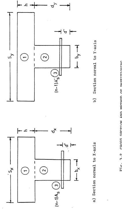
Figure 3.1 shows a typical section of a
rib-stiffened slab. Based on the assumptions made earlier,
the orthotropic flexural rigidities, D and D , as well <y
as the coupling rigidities and. Dg due to Poisson’s
effect, of a m u n c ra c ke d concrete section. (Figure 3.1)
c a m be expressed as
Dx = B + [ - h/2)2/(l - M 2)] + EI^/S^
B = B: + [ Eh(ey - h/ 2 ) V ( l - » Z)] +
= * Exl
D 2 = 11 Dy ((3.4.1.1)
D = flexural rigidity of tlie flange- plate with.
3 2
respect to its middle- plane.,. Eh/l2 (1 -m ) ,
R = modulus of elasticity of concrete
= 57000 ( t ' a ^
£* = 28: day concrete cylinder strength, i m psi
C.’
h = thickness of the flange plate
f i = Poisson's ratio of concrete
= ( f ^) V3 5 0 ( 23)
S„(Sy) = spacing of the longitudinal (transverse) ribs A.
ev (e.r) = depth, of neutral plane from the top fibre x y
for bending i m the x - (y -) direction, i.e.,
ex = + A / 2 ^ + (n “ l)As (h + dx - d')
+ Sxh 2/ 2(1 - w 2 )}/ j + (n - l)hs
+ Sxh / a - m 2 )}
= { *>ydy(k + dy/2 ^ + (n “ l)A'g (h + dy - d"),
+ Syh 2/ 2(1 - y 2 )f/{bydy + (n - l)Ag
+ Syby'Cl - M 2)] (3.4.1.2)
I* (l*)= moment of inertia of longitudinal (transverse)
x y
ribo with respect to; the assumed neutral axis,
i .e .,
^ = v y + V 2) - exi2 + - i)as \
{(h + dx - d') - e.x (2 + V ^ / 1 2 (3.4.1.3)
X y = + dy/2^ " ey /2 + (rl ~ d >A s
in which,
n = modular- ratio = E /E„
s c
"b^hy) = width of. longitudinal (transverse) rib;
^(dy): = depth of the longitudinal (transverse) rib;
d*(d") = concrete cover to the centre of the longitudinal
(transverse) reinforcements;
Ag(As ) = area of tension steel in the longitudinal
(transverse) rib;
D (B.) =s flexural rigidity of the flange plate with xl yy
respect to the neutral plane, of the gross
cross section associated with bending in the
- (y-) direation.
3.4.2 Torsional Rigidity
The twisting rigidity of an uncracked section of
an orthogonally rib-stiffened concrete slab is estimated
by using the. membrane analogy method as proposed by
Timoshenko and Goodier (35). Ike stiffening effecrfc
afforded by the rib stiffeners (beam stems)' in the orthog
onal direction to the one under consideration, is taken
into account. Referring to the- tee-section shown in Pigs.
3 .2 . (a) and 3,.2 (b) and considering the geometry of the
deflected membrane, the torsional, constants for the
rec>-added to yield the torsional constant of the cross-section.
Thus, for a section normal to y— axrs (Pigs. 3..1 and 3.2(b)),
jy - Ji + Jg + J-3
(3.4.2.1J
where,
J^, J 2 and J-, are the- contributions of areas(T) ,
(D.
and (3
) respectively, defined asJ, = 1/2 L S li.3 Um
J 2 - EilV y f0E V V
J2 = W j £ o r * y » ay
, 2 J
3
= 4*^ (n -1
) (A^)/t(3.4.2 .2 )
in which, is the constant for rectangular sections
in torsion (35)>.. The contribution reinforcing
steel is calculated, by transforming tbe area of steel into
equivalent area of concrete. Tbe contribution. «T^, being
relatively small, can be ignored in. a practical, design.
-Por tbe calculation of a reduction factor of l/2 is
used wbich accounts for tbe continuity of tbe slab, this
being distinct from tbe top flange of an isolated tee—
section. Because tbe slabs considered herein, are stiffened
by ribs in two orthogonal directions, tbe torsional con
tribution of tbe slab i n one direction, (see batched
area in Pig. 3^1) is augmented, by tbe stiffening rib i n
the orthogonal direction in. tbe following manner:
Considering tbe section normal to the x- axis
(Pigs,. 3.3. and 3..2 (a)), tbe presence of the transverse
slab. S to a value denoted by J (s+W)* Thus, the modified
value of for the hatched area (normal to the y- axis)
becomes,
(Jl^ modified = ^Jl^ ^j (s+w)//js^ (3.4.2 .3)
Thus,, Eq. (3.4.2.1) is modified to,
Jy = ^ m o d i f i e d + J 2 + J3 (3.4.2.4)
where,
J is the torsional constant of the cross-section
normal to the y- axis..
The torsional rigidity D is now given by,,
y*-D,
= (3,4.2.5)
where, G = shear modulus = E/2(l + m )
Similarly, the torsional rigidity, ^x y , of a section
normal to the x^- axis (Figs. 3.1 and 3.2(a)} can also
be calculated from the equation,
Dxy = GJx/Sx (3 .4 .2 .6 )
where,
J is the torsional constant of the cross-section
normal to the x- axis.
3. 5. Rigidities of Orthogonally- Rib-Stiffened
Cracked Sections '
3*5.1 Flexural Rigidities
After cracking of the concrete section, the
structure continues to behave elastically, provided,
the stress in the steel is below the yield point and
the compressive stress in the concrete does not exceed
0.5 f«. In addition to the assumptions made in section
v
3 .2 , it is assumed that the tension cracks have pro
gressed to the neutral axis (assumed to be in. the flange
plate, which is generally the case). For the computa
tion of. the rigidities, the transformed section consist
ing of concrete [and (n - 1 ) times area of the compress
ion steel.,, if provided] i n compression and n times
the area of the tension, steel is used. Eased on the
above simplifying assumptions, the rigidities of the
cracked section can be expressed as,.
where,.
I (I ) =• moment, of inertia of the concrete
cx x c y /
[and (n - 1 ) times area of compression steel, if
any] in compression about the neutral axis for (3.5.1.1)
bending in the. xl- (y-) direction, respectively, i.e..,
if the neutral, axis lies in the flange- plate (which,
is generally the case),
respect; to the neutral plane of the gross cracked sec
tion associated with bending- in the xr- (y~-> direction.
The location of the neutral axis kd^, or kd^
is determined by equating tile tension force to the
compression force on the section. Thus, by assuming
that the neutral axis lies in. the flange plate, hd^.
is given by,
R eproduced with perm ission o f the copyright owner. F urth er reproduction prohibited w ith o u t perm ission.
V
= sy(
l
c
V 3/3
l«^(lQTr) - moment: of inertia of the transformed steel
section about the neutral axis for bending
i n the x:- (y-) direction respectively, i.e.,
D*(d ') = flexural rigidity of the flange plate with
n&a j(h + d^— d*) - - S^Ckd^)2/^!. - m 2) = 0
3.5.2 Torsional Rigidity
For a rib-stiffened slab construction,
it can be shown (31) that,
(Djjy + + D1 + D 2) = z s . 0 i j i y ) ' (3. 5.2.1)
or,
K = (B + B + B1 + B 2 ) / 2(BXB )1 (3.5.2.2)
Experimental studies conducted have shown
that for this type of slabs, = D .
Thus, Eq, (3.5^2.2) reduces to,
K = (2D + Bj + B 2 ) / 2(BxBy )* (3.5.2.3)
Henna,
Dxy = “ (D1 + D‘2} 7 2 (3-5.2.4),
The co-efficient K is a torsional parameter
with a lower limit of zero (for a grillage with members
having no torsional rigidity) and an. upper limit of
one (for a true orthotropically reinforced slab).
It: is reasonable to assume that the co
efficient K. remains the same, before and after cracking
of the concrete.. Thus, the co-efficient K can be
flexural and torsional rigidities from Eqs.
(3*4.J-.l) and (3.4*2..5),respectively. Mow, the
post-cracking torsional rigidity, DXy« c a m be det
ermined from. Eq. (3. 5*2.-4) i m which D^, D^, and
D 2 are estimated from Eq* (3.5ul.l) fbr the
posifc-cracking condition*
3 ..6> Rigidities of. Mon-rOrthogonallV' Ribr-Stiffened
Slabs
In the structures considered he
rein, anisotropy is provided by a parent iso
tropic plate to which are. securely attached one
or. more distinct systems of parallel straight
reinforcing rib members, as shown in Figs. 3.3
and 3.4. The parent plate is sufficiently thin,
that it is considered, i m a state of plane stress
and the stress i n the rib; stiffeners is assumed,
constant through their cross-section. The rib
stiffeners are made from the same material as the
parent plate and they provide more stabilization
to the structure which makes the structure more
efficient i n resisting compression. For estimating
the rigidities ^ l * ^12* D16» B 22♦ B 26 anxi I)66
such structures, appropriate contributions of slab,,
swept, ribs and ribs i n the orthogonal directions
are required to be taken in±Q' account..
Referring to Rigs. 3.5 and 3 .4:, it is seen
that the typical system of.' skew ribs is incline! r
at: a m angle a , to the. QY axis. I f defines
the-"effective rigidity" of the uniformly distrib
u t e ! skew ribs under the assumptions already made,
r.
then this resultant. (EI^J can be resolved into direct
components by using the transformation:
-
-
“
Dii
_4
m
.0
0
0
0
0
D12
0
l^m2
0
0
0
0
.^ 6
V
0
0
1m3
0
0
0;
SS
a**
n 22
0
0
0
l4
0
0
D 26,
0
0
0
0
l3m
0
D66
0
0
0
0
0
1
2 2
1 m
(3-6.!)
where
1 s cos a
m = sin a
t> 1 r,1 -n» tv* . a r ® '^a -e contributions
"rk* * \ 2 ’ "16* 22*' 26 66
from the skew ribs tc the rigidities ^ j . 2 f ^ 1 61
D 22, D 26 and Dgg*respectively,
i
Iv = moment; of inertia of the skew ribs with
respect to the assumed neutral axis, i.e.,
JT = V M (h+ d- / 2) - ev f 2 + - 1 ^ S T
(3.6.3)
j(h + dv - d^J- - ev }2 + 6 ^ / 1 2
in which,
ev =s depth of neutral plane from the top fibre
for bending in the V- direction, i.e.,
ev = |bv dv (h + d^/2) + (n - l)As v (h + d^ - d^>
+ Svh
2/2
(1
- m2)!/ {
+
0
*-
1
)ASV
+ Svh (1 - m 2)} (3.6.4)
hi = thickness of flange plate;
sv = spacing of the skew ribs;
b^ = widthi of the skew ribs; and
d^. = depth of the skew rib.
d^ = concrete cover to the centre of reinforcement;
in the skew rib#.
A — area of tension, steel in the skew rib
sv
Thus, for a non-orthogonally rib-stiffened
plate withi skew stiffeners and ribs stiffeners
along-the x- direction (Figs. 3*3, 3.5), along-the anisotropic
rigidities can be calculated, by the following equa
tions :
= D + Eh. (ev - h/2)2 / (1 - « 2) + El^m4 /
+ < / 3X
D12 = + »Eh. (ev - h/2)2 / (1 - m 2 ) + 3I^L2m 2 / S^.
2
D16 = f D + ,uEh (e^ - h/2) / (1 - i» > + El^lm3 /
D 22 = D + Eh (ev - h/2)2 / (1 - * 2) + EC^l4 / ST
D 26 = „ D + ^E h (ev - h/2)2 / (1 - „ 2) + EI^L3m / Sv
“66 = ^ / Sx + / Sv
(3.6.5)
where
'IL, D „ 0 = bending-rigidities in. the x- and
y--Llf c. t L
directions, respectively;
Dgg =•■ twisting-rigidity of-the plate;
B12» D 26> = additional coupling rigidities of
the plate.
The rest of the parameters used i n Eqs. (3..6*5)
If a structural system is reinforced with. skew
ribs and ribs, along tbe y direction (Figs. 3.4 and 3.5),
them the above equations are modified to account for
ribs in the y direction, and rigidities are found from
the expressions,
= D + Sh (eT - b/2)2 / (1 - m 2) + EX/14 / ST
D12 = v B + nEh (ev - b/2)2 / (1 - M 2), + EI^L2!)!2 / Sv
B^g = n D + n Eb (ev - b/2))2 / (1 - J. 2) + SI^Lm3 / ST
D 22 = B + Eb (e^ - b/2)S2 / (1 - M 2)> + EI^L4 / Sv
+ / * 7
D 26 = ),D + it Eb (ev - b/2)2 / (1 - » 2> + EI^l3m / Sv
D 66 = CTy / Sy +
(
3.
6.
6)
As a check about the accuracy of the Eqs. (3.6.5)
and (3.6.6)i, by substituting a = 0 (i.e. skew ribs
are oriented along y- axis), or a = 90 (i.e. skew ribs
are oriented along the x- axis), these equations be
come identical, to the ones for orthogonally stiffened
slabs as illustrated in section 3.4.
CHAPTER I¥
MATHEMATICAL FORMULATION POR THE EXPERIMENTAL
STUDIES
4.1 Rigidities of Orthogonally Rib-Stiffened Slabs.
The bending and twisting moments, associated,
with an orthotropic slab structure can be expressed
as (36),
w =s twisting curvature associated with the twisting
t x y
moment M ; and
x - Y
w = lateral deflection. in. the Z- direction of a “x = - (DxwX -XX
in which
M = moment vector in the y- direction;
M = moment: vector in:the x- direction «y
M = twisting moment vector in the x- and y- directions;
w ,w s curvatures associated with the-- moments ML and
• xx • yv x
point on the structure (Pig. 3.1).
Assuming, that in the laboratory tests,
it ,is possible to apply pure bending moments Mx and
M and a pure twisting moment M , then, for the case
Or O'
w h e n only a pure bending moment, Mx , is applied to
a slab, and, M„ = M _ = Q, Eqs. (4.1.1) yield,
y xy
w ,xx
S
2c A c
w ,yy “ ~ sxy^2c
(
4
.
1
.
2
)
in which,
Sxx =
/
<DXD 2 - DXV
S s D„ / (D D 0 - D j J
xy 2 ' v i 2 x. T
(4.1.3)
Similarly, when only My is applied and = MXy - 0,
w , y y S y / L y
,xx = SyxMy
w
(4.1.4)
in which,,
Syy = Dx / ( V , - DxB y )
Syx = D1 / (DXD2 “ DxJV
(4.1.5)
Solving-Eqs. (4.1.3) and. (4.1.5) yields,
D = S / ( S S - S S J 1
x yy ' v xy- yx. xx yy' 1
(4.1.6)
D = S / (S S - S S ) I
y xx ' K xy yx. xx yy' /
Thus, by applying a known moment: M • to one. slab
•V
specimen and a known moment M to another identical
tf
specimen and measuring the resulting curvatures, the
values for , Sxy. , Syy and can be calculated
from Eqs. (4.1.2) and (4.1*4).. Then, the flexural
rigidities D and D can be determined from the Eqs.
x. y
(4.1.6). The bending and twisting curvatures can.be
calculated by measuring deflections of the bent sur
face of the slab (3).
To deduce the torsional rigidity D , the speed-.
m e n is subjected to a known, twisting moment, M .
The twist of the surface w „„ cannot be determined , xy
directly; thus, M o h r ’s circle for curvature is used
i n this determination. Consider a set of rectangular
axes, r and. t, inclined to the x- and y- axes by an
angle 0- (Pigs. 3.1 and 4.1 Ob)). -The curvature and
twist in the r and t- direction, at a point where r
and t are normal to each other c a n be expressed in.
terms of the known curvature and twist: at the same point,
and in the same plane as the r- and t- axes. This
relationship is given by (3)
w ,rr = 'v,3accos2« + w lXy 3:La29 + w ,yysia2e
w = w sin20 - w sin2 0 + w ,_rcos2 q
t u u (Xjt , xy j yy
(4.1.7)
where,
w ,rr’ w , are the curvatures in the r- and
t-directions.
t
Thus, assuming that a pure twisting moment, M , xy
is applied to the slab specimen (Fig. 4.1 (b)) and
that the curvatures are measured in x, y, r and t
directions, the value of the twist of the surface,
w , can be calculated from Eq. (4.1.7). If (? =
t xy
45 , Eq. (4.1.7) yields,
w ,xy = (w,rr " w ,tt>/2 (4.1.8)
ELence,, the torsional. rigidity, Dx y , can be determined
from the last of Eqs. (4.1.1).
4.2. Rigidities of Non-Qrthogonally Rib-Stiffened
Slabs
I m order to estimate the rigidity constants
of non-orthogonally rib-stiffened slabs by measurements
of bending and twisting curvatures of test specimens,
it. is assumed that plane sections which in the
deformed state of the plate are normal to its
surface remain, plane and normal to the bent, middle
surface during the bending. Also the normal, stress
«r in the cross-seation parallel to the middle plane
is assiamed to be small as compared with the stress
in the transverse cross-section.
If u and v are the displacements of any point i n
the direction.of x- and y- axes and w (x,y) is the
defleotion of the middle plane, it follows from the
first assumption,
u = -zw v = -zw .
t j it f
(
4
.
2
.
1
)
then,
e , = -zw xx.
e . = -zw y
r *y
, y y
2zw xy
(4.2.2)
Prom the generalized H o o k e ’s Law,
fx " ^ l ' x + al 2 cry + ^ ’’xy
e y = y L + a22ffy + a 2 6rxy
Txy * + a 26°y + a6 6 rxy
(4.2.3)
° x z(Bllw ,xx + Bl2w ,yy + 2Bl6w ,xy)
„y = - - B 22w f<yy + 2B26w >xy)
Txy = " z ^Bi6w ,xx + B 26w ,yy + 2B66w ,xy^
where,
,B U . = 1//N'(a22 a66 ~ a 26J
B12 = 1//N ^al6 a26 “ a12a66^
B 16 = 1//;N ^a12a 26 “ a22al6^
B 22 = ^ “ ^ 6 ^
(4.2.4)
(4.2.5)
and,,
N =
^a12al6
(alla 22 - af2)
a1 2 ’ * 1 6
a12» a 22» a 26
a1 6 » a 26» a66
(4.2.6)
Nfow the bending and twisting moments can be expressed
as.
h/2
= X
h/2 V d Z^
■ X
h/2 y(4.2.7)
h/2
M = M = f r zdz
xy
yx
J_ ^/2
xy
Prom Eqs. (4.2.4) and (4.2.7)
Mx = - (Dllw ,xx + D12w ,yy + 2Diew ,xy^ ^
M y = - (D12w >x x + D 22w iyjr + 2B2Sw lXy ) K4 . 2. 8)
Mxy = “ ^ 1 6 W (XX + D 26w ,yy + 2D66w >Xy)
Rigidities of the anisotropic plate, D . •, are
X J
related to as,
Did = H i j ^ / 1 2 (4.2.9)
For the anisotropic plate under consideration,
skew rihs are inclined to the OY axis at an angle of
a. The co-ordinates of the rectangular (x,y,Z)
and oblique (u,v,z) systems of axes (Pig. 4.2) are
related by,
u = x + y tan <*
and v = y/cos a
u y. = tan or
V = l/cos o:
t c f
(4.2.11)
The displacement function w(x,y) can be expressed
a.3,
W , S W ... U „ + W V
,X u ,x ,v ,x
= w u
w T = w u + w . v „
»y ,u y ,v ,y
= w ,, tan« + w /cos a
,U j V '
(4.2.12)
A£ter a seaond differentiation with respect to
x and y f Eqs. (4.2.12) yield,
w
xx = w uu
w
»xy = W , u u 't e a “ + W , u / < M S a (4.2.13)
w
C C
= w „„ tan« -f 2w tan o/cos + w /cos a
, yy7 > uu , uv , vrr
where,
w . w
, u u f , w curvatures due to bending in. the
u and v- directions.
w lvtr. = twist of.' the surface with respect to the
u and v- sixes. ,UV
By substituting i n Eqs. (4.2.8), the values, of
curvatures from Eqs. (4.2.13), the following expressions
for the bending and twisting moments are obtained:
2
= - f D Xlw ,uu + D1 2 (w,uu + 2 w ,uv / c o s *
2
+ W |VT ,/c.os a ) + 2Dl6 (w>uu t a n a + w^uv/cos« ) (
2
M y = “ )DI2w ,uu +
B22
tw ,uu t a n “ + 2 w ,uv t a a a / < ! o s “2
+ W jVV/cos a ) + 2D26 (w >u u tan « + w^uv/aos « )|
2
M x y = - 1 D X6W ,UU + D 26 (w,uu ta n a + 2 w , w 1 ® W < » s a
.2
+ w w /aosa ) + 2D66 (w >u u t a n a + w uv/aosa)}
(4.2.14)
To determine the- rigidities of the structure
from the above equations, pure bending moments, Mx
and M , and a pure twisting moment,, Mx y , are applied y
separately to the test specimen (Pig. 4.3).
1st Case
the. 2t- axis (Fig. 4.3 (a)).
Thus, Eqs. (4.2.14) will he as follows:
2
- Dllwl,uu -
D12
(wl ruu t £ m “ + 2wl,uv t a m a2
wl , w /o:os
a
> -2D16,
(w1,u u tsm a + wl,uv/coso > = 02
" D12w1,u u " D 22 (w1,u u tan a + 2wl,.uv tan- “ /cos ° +
2
wl , w /cos ' > ~ 2D26 <w1,u u W “ + wl , u / oos “ > = H j
- D_ ,-w, , - (wn tart a + 2wn tan, a / cos a +
16 l,uu 26 ' l,uu l,uvr
2
w l , W ' 0103 0 } “ 2D66 K . u u t a n ° + wl,uv/ c o 3 ‘‘ > = 0
(4.2.15)
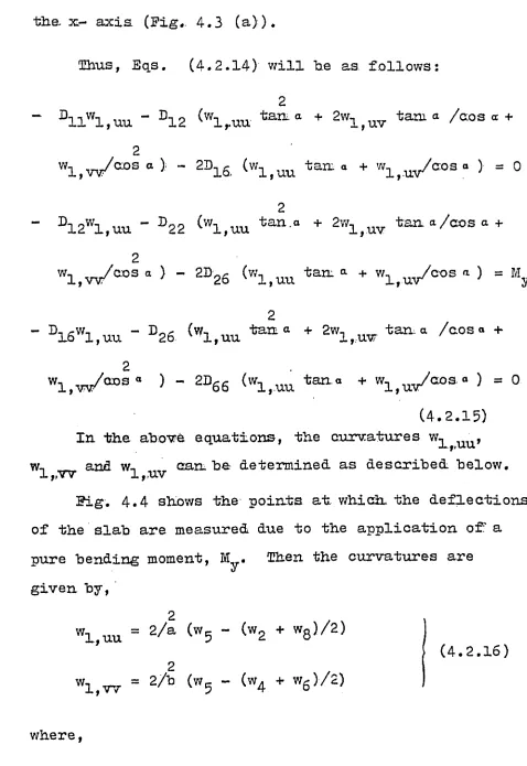
In the above equations, the curvatures w^ u u ,
w-, __ anfl w-, ca n he- determined as described below.
l,,w
1
,,uvFig. 4.4 shows the points at, which. the deflections
of the slab are measured due to the application o f a
pure bending moment, M . Then the curvatures are
u
given by,
2
wl,uu = 2//a (w5 “ (W2 + w8 )//2)
2
w! , w = (w5 ~ (w4 + w 6 )/2^
where,
(4.2.16)
w 2* w4* W 5J w6* an<^ w 8' are ^e:£leations measured
at. points 2, 4, 5, 6 and 8' respectively.
a = spacing- of. points. 2 and 8 from point 5.
b. = spacing of points 4 and 6 from, point 5.
For determining the curvature w , .ft is
p UV
necessary to find the curvature w , with, respect:
to the x- and y- axes. As described in section 4.1,
the curvature w is calculated b y considering a
set of orthogonal axes r and. t, inclined to the
x-and y- axes by a n angle 6 (Fig. 4.4). I f 9 = 45 ,
.
•
ffcom Eqs. (4.1.7)-,
wl (Xy = (wl,rr - wl,tt)/2 (4.2.17)
where,
Wm , w, - the curvatures in_ the r and t
l,rr7 i,tt
directions i.e.,
2
i,rr = 2/° (w5 - (w3 + w t)/2)
w.
(4.2.18)
2 « t .
,)/
2)
wl,tt. = 2//s (w 5 " (v,i + w 9 ‘
in v/hich,
w , w w-!, wl are the deflections measured at points
3 * 7 * 9
3, 7, 1* and 9* respectively.
a a spacing of points 3 and 7 ftom point 5.
to axis r passing through points 3, 5 and 7. In. this
case, it will not. he required to measure, deflections
i t
at points 1 and. 9 , in order to obtain curvature w^
Mow, the curvature w^ can he calculated from
the second of the Eqs. (4.2.13) , which can he express
ed as,
wl,uv = (wl,xs:. - wl,uu tan a >eos a (4.2.19)
. Having known the curvatures w^ u u , w^ w and
w, , the uhkowns in. the Eqs. (4.2.15) are the
rigid-J> f IXv
ities of the slab:, •D12* d i.6* 'D22, '°26 an(i ^66*
2nd Case
Moment M is.applied about y- axis and M y =
= 0, and let w = w 2 (Pig. 4.3 Ob)).. Substituting
in. Eqs. (4.2.14) yields,
" D11w2,u u “ D12 (w 2,u u. + 2w2,u v / “ » ■ +
2
,iVW/cos. ) - 2D16 (w 2,u u ta“ ° + w 2,uv/c o a '1 } = “x 2,
“ D, oW12 2,uu D 22 ^w 2,uu'te“ a + 2w 2,u v - t a u W e o s a +
» 2i„ / o » s a ) - 2D26 (w2<uu tarn a + w ^ ^ / a o s . ) = 0
- D16w2,u u “ D 26 (w 2,.u u tan a + 2w2,uv +
2
w 2,-m/ao3a ) ~ 2B66 (w 2,uu t a m a + w 2,uv/oos a > = 0
(
4
.
2.
20)
From tbe above tbree equations, tbe unknown curva-t
tures w g w 2>vv- w 2,uv can 'be determined in tbe
same manner as described earlier i n tbe I s c a s e ; "
After substitution of’ tbe values of tbe curvatures
i n Eqs.. (4.2.20), tbe unknowns are tbe six rigidities.
Dll» ^12* D16» D 22» D 26» arui
D66-3rd Case
Considering tbat = 0), and a pure,
torsional moment, is applied to tbe structure.
Let: w = w^ (Eig. 4.3 (e))> tbe Eqs. (4.2.14) take
tbe form,
2
- B 1 1 w 3 , u u -
B12
(w3 , u u tantt + 2 w 3 , u v t a a “ / 003a +2
w 3 , w / ° osa) “ 2B16 (w3 , u u itaaa + w 3 , u y ° ° s o ) = 0
2
- B12w 3,u u " D 22 (w3,ttu t a n “ +
2
w 3,uv t a n “ / c o s » +■2 .
2
D1Sw3,uu “ D26 ^w3,uu ’f c a r L a + 2w3jUV tan a /cos « +
2
w3,vV/G;oaa) *“ 2D6d (w3,uu taaa + = Mxy
(.4.2.21)
Similarly, the unknown curvatures can. also he
determined for the above equations.
Determination, of the Rigidities
There are nine equations in (4.2.15), (4.2.20)
and (4.2.21) which contain six unknown rigidities
£>11 > D1 2 T D-^g, D22,, D2g and Dgg. Thus, three experi
ments can be conducted, by applying’ pure bending: mom
ents, My and Mjj, in the first two experiments and a
pure twisting moment, in the third experiment which
will result in. Eqs,. (4.-2.15), (4.2.20) and (4.2.21),
respectively. Six equations from (4.2.15) and (4.2.20)
can.be used to determine the. six unknown rigidities.
The rigidities D^, D^2, D^g, D22, B2g, and Dgg can
also be determined fhom Eqs.. (4.2.15) and (4.2.21)
(or from Eqs. (4.2.20) and (4.2.21)) and the results
can be compared with, those obtained earlier by using
Eqs. (4.2.15) and (4.2.20)..,
CHAPTER V
EXPERIMENTAli INVESTIGATION
5.1 Sco-pe of the Exnerimental Programme
The experimental programme consisted of nine
tests on orthogonally rih stiffened concrete slabs.
These tests were classified into three series of test,
specimens. Each series consisted of three types of
specimens, two were rectangular in. plan for bending
tests (one in.the x- and the other in.the y- direction;
and the third was square i n plan for the pure twist
ing test-. Mathematical formulations developed in
section 4.1 were used to calculate the flexural and
torsional, rigidities.
5.-2 Materials
5,2.1 Concrete
High early strength Portland Cement manufac
tured. by Canada Cement Company was used in all the
slab specimens. The maximum size of the aggregate
was restricted to 0..25 inch (6.4 ram) since the
narrowest dimension between the sides of the
form-work, was 1.25 inch. (32 mm) and the concrete cover
to the centre of steel reinforcement was 0.5 inch.
(12.7 mm). The combined aggregate was prepared b y
mixing 9'.. 7$ coarse aggregates and 90.3$ fine sand.
fineness modulus; of 2.42. The concrete, mix used
had a. water-cement ratio of 0.75 and the
aggregate-cement ratio was 5.0, both by weight.. Mixing of
concrete was done in an Eerich Counter Current
Mixer, Model EA2 (2W) with a capacity of five. cu.
ft. Only one batch of concrete weighing 700 lbs.
was required for each bending test specimen. The
concrete strengths of the specimens tested are
given in Table 5.1.
5.-2.2 Reinforcement
Two plain, mild steel wires of l/8 in
(3.2 mm) diameter were used as reinforcement..
The wires were straightened and twisted together
in the laboratory, keeping the cross-sectional
area the same along the length. The twisted wires
were cut:, cleaned from rust and hooks were provided
at both ends. The stress-strain relationship for
the reinforcing wire is shown in Pig* 5..1. The
modulus of elasticity was found to be 30,400 ksi
(210 GN/m2).
5.3 Description, of the Specimens
A total of nine specimens were tested for
the bending and twisting tests., All specimens had
a continuous slab with a thickness of 1 in (25.4 mm)
and. the depth, of the rihs was 3 in (76 m m ) .
In. each case, the first layer of steel was placed
air 3/8 in (9.5 mm) clear cover, and the second,
layer orthogonal to the first, was placed .jusir
over the first layer. Geometric description, and
properties of these specimens, are given in.Table
5.1. These specimens were classified into three
series.,
There were three specimens in each series.
Two specimens were tested in bending and one in.
torsion. The bending specimens in series A were
80 x 40 inches (2.03 x 1.02. m) i n plan and the
ribs were placed at. 8 in ( 203 mm) spacing in one
direction while in the other orthogonal direction,,
spacing of the ribs was 4 in (102 mm) c/c. The
size of the specimen for the twisting test was
40; x 40 inches (1.02 x 1.02 m).. I n series B-, the
size of the bending specimens was 70 x 35. inches
(1.78 x 0.89 m). and, fcr the twisting test, the spec
im en was. 35- xl 35 inches (0.89 xl 0:. 89 m) in. plan...
Spacing.of the ribs was 7 in. (178 mm) c/c in one
direction and in the other direction, a spacing
of 5 in (127 mm), c/c was provided.. In series C,,
the bending specimens, were 60 x 36 inches (1.52 x
plan.with dimensions of 36 x 36 inches (0.91 xl
0.91 m ) . Ribs were placed at 6 in: (152: mm) c/c
spacing in one direction and in the other orthogonal
direction, \a spacing of 4 i n [(102 mm) ..c/c .was
provided. Reinforcement was placed in the centre
of the ribs for all the nine specimens tested.
5.4 Casting of the Specimens
All the specimens were cast in forms made
of 3/4 in (19 ram) thick plywood. The voids between
the ribs were made by gluing styrofoam blocks to
the plywood form following a marked pattern on.
the wood. The reinforcement was then placed between
the styrofoam blocks in both directions. For the
bending specimens the reinforcement: in the longer
direction was placed first on small wooden, blocks
to keep it 3/8- in, (9.5 non) from the bottom of the
forms. This provided for the minimum cover required
for the steel. The steel in the shorter direction
was then placed on. the top of the reinforcement:
i n the longer direction. Both: layers of reinforce
ment were tied together with thin wire for stability
during casting of the concrete.
Before casting of the concrete, the top
surface and the sides of the form were soaked with
heavy industrial oil. The concrete was then poured,
All the specimens were moist cured for a period
of 14 days.. To determine the compressive strength
of the concrete, three 3 x 6 in- (76 x 152 mm.) concrete
cylinders, were cast with each specimen. These cylinders
were subjected to a compression, test; at the time of
testing of the test specimen.
5.5 Instrumentation
The deflections of. the concrete specimens for
bending and twisting tests were measured by means of
the Hewlett Packard series 71CDT Displacement Transdu
cers. The concrete surface at the location of the
transducers, was smoothed using fine sand paper and
after removing the dust by means of compressed air,
the surface at the transducer locations was cleaned
with acetone. Surface cavities were filled with a n
epoxy resin at the transducer locations. All transdu
cers were calibrated with an electronic voltmeter be
fore testing to establish their calibration factors
(Figs. 5,.,2 through 5.10'). Ehe range of the volt
meter was from mlT to 20Q V. Millivolt range was
used ini all the. experiments to oh bain very accurate
deflections. A Harrison Laboratories Model 6204 B
power supply was connected to the transducer excit