18th International Conference on Structural Mechanics in Reactor Technology (SMiRT 18) Beijing, China, August 7-12, 2005 SMiRT 18-J09-2
DESIGN AND STRUCTURE ANALYSIS FOR THE CENTER POST
OF LOW ASPECT RATIO TOKAMAK REACTOR
Yuntao SONG, Liman BAO, Damao YAO
Institute of Plasma Physics, Chinese Academy of Sciences
P.O.Box 1126, Anhui, Hefei, P.R.China, 230031
T
el: +86-551-5593271, Fax: +86-551-5591310
Email: songyt@ipp.ac.cn
Satoshi NISHIO
Department of Fusion Plasma Research of Japan Atomic Energy Research Institute,
Naka-machi, Naka-gun, Ibaraki-ken 311-0193,JAPAN
Tel: +81-29-270-7263, Fax: +81-29-270-7468
Email: nishio@naka.jaeri.go.jp
ABSTRACT
The center post is one of the critical components for the low aspect ratio tokamak reactor device, which endure not only a tremendous Ohmic heating due to its carrying a rather high current but also a large neutron heating and irradiation owing to the plasma operation. The DS copper alloy, Glidcop®, AL-25 was chose as the conductor material for its adequate mechanical properties and physics properties. The center post has a cylinder structure with lots of cooling channels. The length of center post for the next generation nuclear fusion spherical tokamak reactor device will be more than 10m or 20m. The stability and stress intensity of its structure are very crucial for them. When the applied load is very large and over the structure critical load, the device will lose its stability and collapse. In order to calculate the critical load, a finite element model was used and the force acting on the center post was simulated. The paper has given the thermal-hydraulic and structure analysis results with finite element method based on the small deformation theory. The relation curves and functions for the buckling factor depended on the different length of center post, radius of center post, diameter of the cooling channel and the maximum allowable current density have also been shown.
Keywords: Center post, Tokamak, Fusion Reactor
1. INTRODUCTION
In recent years, Based on the advanced theory plasma physics studies in tokamak and heart-stirring experimental results attained in some spherical torus, the low aspect ratio tokamak has gradually shown a good potential to become an economically competitive fusion reactor. This kind of device not only has tokamak-like safety factor profiles and adequate confinement but also has a strong toroidal paramagnetism and high betas similar to the spheromak, which has already attracted lots of research interest of fusion scientists and brought a number of new experimental machine proposals to promote the further development of magnetic fusion, such as the ARIES-ST in University of California, San Diego (UCSD) and VECTOR in Japan Atomic Energy Research Institute (JAERI).[1-3]
aspect ratio of 1.4 and major radius is 4m gives a center post conductor radius of 1.3m and length of 10~30m.During the plasma operation the center post is one of the critical components for the low aspect ratio tokamak reactor device, which endure not only a tremendous ohmic heating due to its carrying a rather high current but also a large neutron heating and irradiation owing to the plasma operation. The neutron wall loading can lead to more than one hundred displacement per atom (DPA) in the copper after a year of full power operation, which effect badly the life of center post. The resistivity of conductor also will increase with the change of temperature and DPA of the center post, which bring some additional removed heating for the cooling system. In the design of center post all of these cases must be considered together. It is one of the most challenging engineering for the low aspect ratio tokamak to design eligibly such radius and length conductor. So it is very necessary to choose a best water fraction and some other parameters for the center post under some optimization studies including thermal-hydraulic and mechanical analysis.
2. DESIGN OPTION FOR CENTER POST 2.1 Structure of center post
Center post is one part of the TF (Toroidal Field) coils for the low aspect ratio tokamak. It is very important to choose an appropriate type coils, a single turn or multi-turn TF, which is directly effect the ability of carrying current. Although the multi-turn type coil has the advantages of easy fabrication and the Joule losses in power supplies and buses are very low for its smaller units, it also has some demerits such as the turn-to-turn insulation and electrical breakdown is required which reduce the packing fraction due to the requirement of shielding. On the other hand it is a disperse structure, which has not a stronger mechanical characteristic as the monolithic construction of single turn coil. The single turn type coil, which need develop a large power supply system, can carry more current than the multi-turn coil with a same radius because of its high packing fraction and continuity structure. So a single turn was chosen as the center post.
As shown in Fig. 1 it has given the structure of TF coil for the low aspect ratio tokamak. And Fig. 2 shows a geometric representation of the center post with lots of cooling channels distribution along the direction of length in a cylinder conductor. Due to this kind of structure is very like the lotus, it was call the lotus root structure. It can be replaced without disturbing the TF outer legs or other components. The bulk of the heating is ohmic which is uniformly distributed over the cross section while the nuclear heating is concentrated near the surface and decayed along the radius. The coolant was pumped to flow along the channel from the bottom to the top of center post. In the practical engineering, some center post has a shaping structure considered the assembly and some requirements of plasma physics.
Fig. 1 Structure of TF coil for low aspect ratio tokamak
2.2 Material selection for center post
The nearly pure copper such as oxygen-free copper was commonly the conductor of choice for early normal tokamaks because of its outstanding electrical and thermal conductivity. But it is not as strong as the copper alloys, which can provided adequate strength (especially at elevated temperatures) in addition to outstanding electrical and thermal characteristics and were readily available at reasonable cost. Uppermost the copper alloys still possesses a good mechanical and physical properties in the high radiation environment For the low aspect ratio tokamak power plant the material selection of the center post must satisfied these criterions:[4-7]
. Adequate mechanical properties (strength and ductility) at end of life;
.Adequate physical properties (swelling, electrical c onductivity, and thermal conductivity) at end of life; .Availability is required shapes and sizes; and
.Disposability as Class C waste.
The CP, unless well shielded, will be subject to high radiation doses. Potential radiation effects in the centerpost include void swelling, irradiation creep, and degradation of electrical and thermal conductivity, radiation hardening, embrittlement, and activation.
Irradiation at temperatures below 150°C causes pronounced hardening in pure copper and precipitation hardened (PH) and dispersion strengthened (DS) copper alloys. Hardening resulting from low temperature irradiation is accompanied by dramatic embrittlement. The uniform elongation generally decreases to less than 1% even at doses as low as 0.01 to 0.1 dpa. In contrast, the expected dose at the centerpost will be several dpa to tens of dpa.
Oxygen-free copper is unsuitable for operation at elevated temperatures due to annealing and loss of strength. Precipitation hardened alloys maintain their yield strength at elevated temperatures better than oxygen-free copper but diffusion bonding and furnace brazing generally result in unacceptable softening during fabrication. DS copper alloys such as Glidcop AL-15 and AL-25 appeared well-suited for operation at elevated temperature. They adequately resist creep, swelling, softening, and helium embrittlement up to high irradiation doses in the temperature range of 150°C to 350°C (or perhaps higher). DS alloys can be satisfactorily joined by brazing, explosive bonding, or diffusion bonding (hot isostatic pressing). The main concern at elevated temperatures is a loss of fracture toughness. Dramatic drops in fracture toughness at 250°C and under irradiation have been reported. Based these criterions and referred to the test data of ITER for some kinds of copper alloys. DS copper alloys Glidcop AL-25 was chosen as the material of center post for its adequate mechanical properties and physics properties. This dispersion-strengthened copper can be used in the temperature over 500 .At the room temperature the yield strengths is more than 400Mpa and the thermal conductivity up to 350W/m•K. Under the irradiation its volumetric swelling is less than 2% up to an irradiated neutron fluence of 150dpa at 410 to 415,with uniform elongation of less than a few percent at temperature below 250 under a damage level of about 1 dap.
(1) Limitative conditions for the design [8-10]
From the view of the fusion power plant, it is very important to research how to prolong the life span of center post being employed. Some of the cost effectiveness, safety and engineering reliability must be considered during the engineering design, which are all the essential factors. So some parameters must be limited during the study for the center post, such as the maximum rise temperature of the conductor and the velocity of coolant. (2) Limitation for the choosing of the coolant
There are several coolants such as the liquid lithium, liquid nitrogen, gaseous helium and water, which have been used in the cooling system of different tokamak device, can be assessed and chose as the coolant of the center post.
If using the liquid lithium as the coolant, a thin steel sleeve is required between the lithium and the conductor because of material compatibility issues. And electrically insulating coating must be applied to the inside of the steel sleeve to reduce MHD pressure drops to manageable levels. In addition, the engineering difficulties associated with the liquid lithium coolant are severe. If using the liquid nitrogen or gaseous helium, some cryogenic system is required to provide the coolant operating in the temperature of 80-110k(liquid nitrogen) and 30-50K(gaseous helium). These cryogen-cooled option also appear to be much more complex for design and non-economical for power plant. So the ambient water was chosen as the best coolant of center post, which not only has a good thermodynamic efficiency but also has a simplicity design and high economical output for the power plant. The inlet temperature is about 30 and the outlet temperature is low than 100 ,which prevent the water from boiling. Considered the affluence for the engineering design, the 80 was chosen as the outlet temperature.
(3)Limitation for the temperature of conductor
to 0.1 dpa. On the other hand irradiation at temperature above 150 causes moderate embrittlement under the doses up to 5 dpa. The test results also demonstrate that low temperature radiation embrittlement may have a considerable impact on the use of the copper alloys. For the DS copper alloys ,150 appears to a critical temperature for manifestation of embrittlement. When the irradiation temperature more than 150, the DS copper alloys has a satisfactory level of ductility, with irradiated elongation in the range of 50 to 90% of the unirradiated values. And if the temperature less than 150 ~100 the material embrittle dramatically and damage level as low as 0.1 dpa. The DS copper alloys has a good ductility with the rise of temperature, nevertheless if the temperature is very high, the thermal stress for the large deformation and the resistivity of conductor will be increased acutely with the temperature, which is badly for the life of the center post, and an additional cooling system also required. So the 150 was chosen as the limitation for the temperature rise of conductor. [11]
(4) Limitation for the velocity of coolant
The total heat was carried away by the coolant in the center post. On the one hand the high coolant velocity can lead to a good cooling condition and bring a low temperature for the copper conductor, and on the other hand it can lead to adverse effects on safety through erosion of conductor into the coolant stream. Whether the coolant water is used as preheat for the thermal cycle or rejected as waste heat, the erosion of activated copper into he coolant stream will pose a safety issue. The erosion of different alloys of copper were measured by Von H. Sick, Dobson and Whitley with different velocity and characteristic coolant such as the PH, impurity level, oxygenation and coolant channel diameter. It is tend to choose the 10m/s as the limitation of the velocity for coolant of the center post.[12]
3. POWER LOSS ANALYSIS 3.1 Joule heating
For the low aspect ratio tokamak reactor, the Joule heating power is the main heat source for the center post. It is often very high due to its large electrical current and small cross section area, despite low resisitivity of copper. The Joule heating energy will be produced during the large current flowing through the center post conductor
Eohmic =
B
t
l
I
2η
∆
(1)
where I is the total current in the center post
B is the cross-section area of the copper in the center post,
η is the resisitivity of the conductor,
l is the length of the center post,
t
∆
is the time of the operation.3.2 Nuclear heating
During the operation the center post will endure the nuclear heating under irradiation of neutrons from the core plasma. In order to investigate the nuclear heat distribution in the center post at different neutron wall loadig and different thickness of the shielding, a representative model was firstly proposed as shown in Fig.3. There is a relatively thin type 316L stainless steel and water-cooled tungsten shield surrounding the center post conductor,
Fig.3 Representative model for nuclear heating analysis
decay rules were established as functions of the distance from the plasma. Ubiquitous functions of neutron and gamma heating depending on the different neutron wall loading, different thickness of the tungsten shield and different distance from the copper conductor outer surface were finally inferred as follows:
The function of neutron heating attenuating in the copper conductor:
PCu-n 582 . 10 / 38693 . 5 / 21512 . 1 /
max
(
0
.
644
0
.
771
)
x t t n
e
e
e
P
⋅
−+
−⋅
−=
, (2)And the function of gamma heating attenuating in the copper conductor:
PCu-r 13 / 74968 . 11 / 42215 . 1 /
max
(
0
.
405
4
.
429
)
x t t n
e
e
e
P
⋅
−
−+
−⋅
−=
, (3)where t is the thickness of the tungsten shield [cm],
x is the distance from the copper conductor outer surface to its center[cm],
n
P
max is the neutron wall loading [w/cm2].Figure 4 shows the neutron heating and gamma heating in the copper conductor with different thickness of tungsten shield under the neutron wall loading of 5MW/m2 at the tungsten surface facing the plasma.
0 10 20 30 40 50 60 70 80 90 100
0 10 20 30 40
50 Neutron wall loading P
n=5MW/m 2 Nucl ear heat ing rat e ( W /c m 3 )
Radial Position from torus center(cm)
Neutron for 20cm -shield
Gamma for 20cm -shield
Neutron for 5cm thick W-shield
Gamma for 5cm thick W-shield
0 10 20 30 40 50 60 70 80 90 100
0 10 20 30 40 50
thick W
thick W
Fig.4 Nuclear heating along the radial direction with different thickness of tungsten shield
The total energy of neutron and gamma heating power in the center post with different radius and different length of center post can be obtained by the integral method as Eq.4
ET
=
⋅
∫
R
l
0 (PCu-n + PCu-r )·2πrdr , (4)
where R is the radius of center post (m).
4.THERMAL-HYDRAULIC ANALYSIS OF CENTER POST
From the view of energy balance and considered the Joule heating and nuclear heating with different thickness of tungsten shielding, this paper has given some optimization results and some relation curves for the center post including the maximum current density, best water fraction, cooling channel diameter and pump power.
4.1 Power balance in the center post
The increase energy of copper due to a change temperature
∆
T
cu during the time∆
t
cu cu cu
cu
C
Bl
T
E
=
ρ
∆
(5)The loss energy carried by the water due to a change temperature
∆
T
w during the time∆
t
t
T
VA
C
E
w=
wρ
w∆
w∆
(6) The production energy due to the ohmic heatingB
t
l
I
E
ohmic=
η
∆
2
(7)
And the nuclear heating power due to the irradiation of core plasma: ET
η is the copper resistivity (Ω·m)
A is the area of cross section in water cooling (m2) B is the area of cross section in copper (m2) L is the length of center post (m)
Cw is the specific heat of water (J/kg·˚C)
Ccu is the specific heat of copper (J/kg·˚C)
ρw is the density of water (kg/m3)
ρcu is the density of copperr (kg/m3)
V is the velocity of water (m/s)
∆Tw is the average rise temperature of water during time ∆t
∆Tcu is the average rise temperature of copper during time ∆t
The change of energy in the water-cooling copper conductor of length L during a time interval ∆t is
w w w cu cu cu
T
C
m
T
C
m
T
E
t
R
I
2⋅
∆
+
=
⋅
⋅
∆
+
⋅
⋅
∆
(8) Define: The total area of cross section for center post is S (S=A+B)The average current density is
S
I
I=
ρ
The fraction of water cooling is f
The copper resistivity depended on the temperature :
m
Tcu × Ω⋅
+
= −8
10 ) 00415 . 0 1 ( 72 . 1
η (9)
From the Eq.4.4, the function between the average current density and fraction of water-cooling can be found:
) 007138 . 0 72 . 1 /( ] ) 1 ( ) ( 2 . 418 ) 1 ( 1 . 339
[ 2 2
2 cu T w cu T ls f E T l v f f t T
f ⋅∆ + − ⋅ ⋅∆ − ⋅ − +
− =
ρ (10)
Fig.5, Fig.6 and Fig.7 have given the maximum current density in the center post depending on the radius of the center post with different thickness of the tungsten shielding, i.e. with different nuclear heating power. For example, when the average neutron wall loading is 5MW/m2, the nuclear heating power is 1.25W/CC for the 5mm thickness of tungsten shielding, 5.22W/CC for the 10mm thickness of tungsten shielding and 15.12 W/CC for the 20mm thickness of tungsten shielding. It is found that nuclear heating has much less effect to the maximum average current density than Joule heating for center post with an appropriate thickness tungsten shielding. And also it shows that the maximum allowable current density of the center post has little change as itself radius if only considering the heat load not including the structure static stress.
65 70 75 80 85
41 42 43 44 45 46 47 L=10m a d c b M ax im um allow ab le curren t den sity (A/ m m 2 )
Radius of center post (cm)
65 70 75 80 85 26 27 28 29 30 31 32 33 34 L=20m a d c b M a x im u m allow ab le curren t de nsity (A/m m 2 )
Radius of center post (cm)
Fig.6 Maximum allowable current density depended on the radius of center post with different
nuclear heating power (Line a with the Joule heating; Line b with the Joule heating and nuclear
heating with 20cm thick tungsten shielding; Line c with the Joule heating and nuclear heating
with 5cm thin tungsten shielding; Line d with the Joule heating and Nuclear heating without
tungsten shielding); L=20m
65 70 75 80 85
18 19 20 21 22 23 24 25 26 27 28 L=30m a d c b M a x im u m al lo w able c u rrent de nsity ( A /m m 2 )
Radius of center post (cm)
Fig.7 Maximum allowable current density depended on the radius of center post with different
nuclear heating power (Line a with the Joule heating; Line b with the Joule heating and nuclear
heating with 20cm thick tungsten shielding; Line c with the Joule heating and nuclear heating
with 5cm thin tungsten shielding; Line d with the Joule heating and Nuclear heating without
tungsten shielding); L=30m
4.2 Maximum current density and best water fraction with different conditions
From the Eqs.8, under the steady state conditions the function of rise temperature of water with the water fraction can be got:
w w w w w VC f f E l S I VC A S A l I T ρ η ρ η ) 1 ( ) ( ) ( 2 2 − + = −
= (11)
0.0 0.2 0.4 0.6 0.8 1.0 0 20 40 60 80 100 I A=20A/mm 2 I A=30A/mm 2
IA=40A/mm 2 I A=50A/mm 2 L=10m,v=10m/s R ise o f w a te r te m p e ratu re
Ratio of Water Area
Fig. 7 Relation curve of rise temperature and cooling fraction for water
(Fix condition is v=10m/s, L=10m)
0.0 0.2 0.4 0.6 0.8 1.0
0 10 20 30 40 50 60 70 80 90 100 v=10m/s v=8m/s v=6m/s v=4m/s v=3m/s
L=10m, IA=30A/mm2
Ri se of w ater t empe rat ure
Ratio of Water Area
Fig.8 Relation curve of rise temperature and cooling fraction for water
(Fix condition is IA=30A/mm2, L=10m)
From these figures, some design windows can also been attained. Fig. 9 has shown the dependence of maximum current density on the thickness of tungsten shielding and diameter of center post. Fig.10 has shown the dependence of the best ratio of water fraction on the thickness of tungsten shielding and diameter of center post. Fig.11 has shown the dependence of maximum current density on the length of center post.
0.0 2.5 5.0 7.5 10.0 12.5 15.0 17.5 20.0
10 12 14 16 18 20 22 24 26 28 30 32 34 36 38 40 42 44 46 48 50 L=30m L=20m L=10m Diameter of center post (m)
M a x imu m a verag e cu rre n t d ens it y (A/ mm 2 )
Thickness of shielding (cm)
1.70 1.65 1.60 1.55 1.50 1.45 1.40 1.35 1.30
10 12 14 16 18 20 22 24 26 28 30 32 34 36 38 40 42 44 46 48 50
0.0 2.5 5.0 7.5 10.0 12.5 15.0 17.5 20.0 0.50
0.52 0.54 0.56 0.58 0.60 0.62
L=30m L=20m
L=10m
Diameter of center post (m)
B
est rati
o of
w
ater f
racti
on
Thickness of shielding (cm)
1.70 1.65 1.60 1.55 1.50 1.45 1.40 1.35 1.30
0.50 0.52 0.54 0.56 0.58 0.60 0.62
Fig.10 Dependence of the best water fraction on the thickness of tungsten shielding.
Fig.11 Dependence of maximum current density on the length of center post
5. STRESS ANALYSIS OF CENTER POST 5.1 Load cases on the center post[13-16]
During the plasma operation, the center post is subjected to several types of loads including:
(1)Tensile load due to the J×B force acting on the connection interface between the outboard TF coil and the center post;
(2) J×B radial compressive load due to the transition current of the center post crossing the toroidal field; (3) Torque produced by the plasma disruption;
(4) Gravity load and coolant pressure load;
(5) Thermal stress due to the nonuniform distribution of the temperature in the conductor.
The tensile load on the center post arises from J×B force at the interface between the return legs of TF coil current and center post are mainly determined by the current extent, the radii of the center post and TF coil outboard returning. It can be accommodated by providing a bellows and sliding electric connection at the upper extremity or add a reverse hydraulic pressure on the center post to counteract the tensile force. The transition current in the center post interacting with the toroidal field will bring out the radial compressive stress on the center post. From the view of the qualitative analysis the tensile electromagnetic force FZ and the radial compressive
electromagnetic force Fr can be write as: [13]
a
R
a
J
F
zln
8
4 2 0
πµ
3
3 2 0
J
a
l
F
rπµ
=
, (13)where R is the radius of the outer legs of TF coils (m),
a is the radius of the center post (m),
J is the current density in the center post,
µ0 is the magnetic permeability of free space.
Plasma disruption will mainly affect the plasma facing components. Compared with the above tensile and compressive loads on the center post, the stresses caused by the torque due to the induced current in the center post and the poloidal field during the disruption is very limited and easily endured, which has estimated in some spherical tokamak experiment devices [8].The gravity load is so small causing only a stress of few MPa that it is not taken into account here. The thermal stress due to the nonuniform distribution of the temperature in the conductor is one of important limiting conditions for the allowable maximum current and structure design of the center post.
5.2 Thermal stress analysis
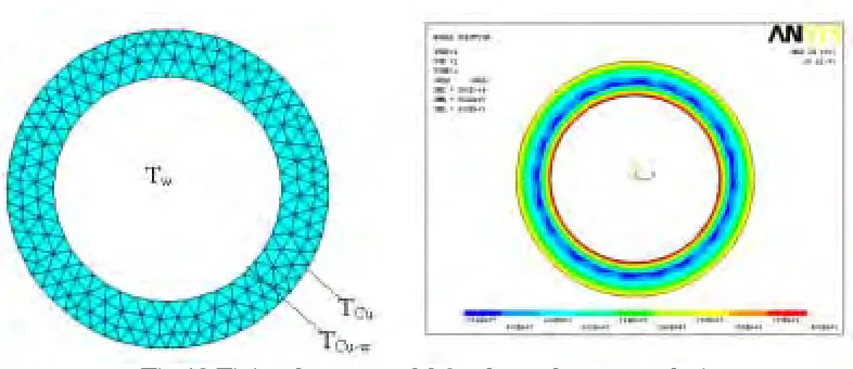
Thermal stress is mainly due to the temperature gradient. Taking a cross-section of the center post there are lots of cooling channels in the center post. Temperature of the area will be low near the coolant and high away from the coolant. For this reason, the distribution of temperature in the center post is formed and causes thermal stress. Considering the cooling channels distributed uniformly one unit-cooling channel and its corresponding copper conductor was chose for analysis. The finite element model as shown in Fig.12 was defined with the parameters such as the diameter of cooling channel, area of the copper conductor and the temperature of the inner surface of the copper conductor, which are all based on the thermal analysis for the center post. Table 1-3 listed their parameters and thermal stress. The boundary conditions is that the water in the cooling channel defined as 80 and the copper conductor defined as 180 .
Fig 12 Finite element model for thermal stress analysis
Using the finite element method, the maximum thermal stresses, σT have been analyzed with different water
fraction and the length of center post as shown in Fig.13. From this analysis the maximum general thermal stress
T
σ
can be reach 144 MPa when the maximum temperature rise of the center post is 150 .Table1 Geometrical dimensions and thermal stress with 10m-length center post
Water fraction (%) 10 21.3 40 50.3
Temperature of out surface of copper ( ) Tcu 180 180 180 180
Temperature of inner surface of copper ( ) Tcu-w 115 132.6 146 153
Temperature of water ( ) Tw 80 80 80 80
Current density (A/mm2) 26.5 37 44.7 45.5
Diameter of cooling channel (mm) 18 25 30 33
Thermal stress (MPa) 115 78 51.4 39.5
Water fraction (%) 12 30 41 50
Temperature of out surface of copper ( ) Tcu 180 180 180 180
Temperature of inner surface of copper ( ) Tcu-w 107 120 127 130
Temperature of water ( ) Tw 80 80 80 80
Current density (A/mm2) 20 29.3 31.7 32
Diameter of cooling channel (mm) 25 35 40 43
Thermal stress (MPa) 128 94.4 79.9 73.2
Table3 Geometrical dimensions and thermal stress with 30m-length center post
Water fraction (%) 10 15 31.6 51.3
Temperature of out surface of copper ( ) Tcu 180 180 180 180
Temperature of inner surface of copper ( ) Tcu-w 100 104 111.7 121
Temperature of water ( ) Tw 80 80 80 80
Current density (A/mm2) 15 18.75 24.3 26.2
Diameter of cooling channel (mm) 26 30 40 50
Thermal stress (MPa) 144 130 106 86
0 10 20 30 40 50 60
30 40 50 60 70 80 90 100 110 120 130 140 150
L=20m L=30m
L=10m
M
a
ximum therm
a
l t
tress (MPa)
Water fraction (%)
Fig.13 Thermal stress as a function of water fraction and center post length
5.3 Factor of stress concentration due to cooling channel
For a solid cylinder structure, the factor of stress concentration is 1 under a uniform radial pressure load. But for the lotus structure of the center post, it must be more than 1 due to lots of cooling channels disturbing the continuity of the structure. Before the structure analysis of the center post, it is useful to investigate the essential relations of stress concentration depended on the water fraction and the cooling channel diameter.
Finite element models with different number and different diameter of cooling channels as shown in Fig.14 were used. By applying a unit constant compression pressure (100MPa) in the radial direction and the maximum stress and local stress concentration were obtained. The stress concentration mainly appears in the area around the cooling channel as shown in Fig.15.
From the analysis it has be found that the maximum stress is only appeared in a very small local area around the cooling channel, which mainly produced by the local primary membrane stress and bending stress. For this place the maximum stress concentration factor was defined as Kmax and the average stress concentration factor Ka was
Fig.14Finite element model for the factor of stress concentration
Fig.15 An example of the stress contour for the center post (water fraction is10%, cooling
channel diameter is 20mm,the maximum stress concentration factor is 2.19,the average stress
concentration factor is 1.11)
0 5 10 15 20 25 30 35 0.8
1.0 1.2 1.4 1.6 1.8 2.0 2.2 2.4 2.6 2.8 3.0 3.2 3.4
K
a
K
max
Str
e
ss concentr
a
tion
facto
r
Water fraction (%) Diameter of colling channel=15mm Diameter of cooling channel=25mm Diameter of cooling channel=35mm
Fig.16 Stress concentration depended on the water fraction and cooling channel diameter
If based on these parametric analysis data, the function of factor of stress concentration could be deduced. One is the maximum stress concentration factor Kmax and the other is the average stress concentration factor Ka.
)
94
.
1
0053
.
0
(
)
,
(
0.0181max
φ
=
⋅
−
φ
+
p
e
p
K
, (14))
98
.
0
0027
.
0
(
)
,
(
φ
=
0.0181p⋅
−
φ
+
a
p
e
K
. (15)6.BUCKLING ANALYSIS FOR THE CENTER POST
The center post has a cylinder structure with lots of cooling channels. The length of center post for the next generation nuclear fusion spherical tokamak reactor will be more than 10m or 20m.[15,16] When the applied additional vertical force F is very large and over the structure critical buckling load, the device will lose its stability and collapse. So the structure stability of the center post has been studied for the low aspect ratio tokamak device. Based on the buckling theory of the Euler column it can be found that the structure length and the geometrical moment of inertia mainly determine the stability of the center post of low aspect ratio tokamak.For the structure of the center post, which has lots of cooling channel, the geometrical moment of inertia directly associated with the diameter of cooling channel, distribution of cooling channel and the fraction of cooling water. Considered the cooling channel distributed uniformly the geometrical moment of inertial[20] for the center post with lots of cooling channels:
) 4 64
( 64
2
1 4 4
d R d
N D I I I
n i
i i
t
π π
π
⋅ + ⋅ − = −
=
∑
∑
=
. (16)
where I is the geometrical moment of inertial (m4) D is the diameter of center post,
d is the diameter of cooling channel,
Ri is the distance from the center of the every cooling channel to the axis of center post,
N is the number of cooling channel.
Fig.17 shows the geometrical moment of inertial depended on the cooling water fraction with different diameter of center post. With the increment of the length of center post and water fraction the geometrical moment of inertial will be decreased so that the stability of the center post is also weak gradually.
5 10 15 20 25 30 35 40
500 1000 1500 2000 2500 3000 3500 4000 4500
Geometr
ic
a
l moment iner
tia (
x
10
-4 )
Water fraction (%)
Radius of center post is 65cm Radius of center post is 75cm Radius of center post is 85cm
Fig.17 Dependence of the geometrical moment of inertial on the cooling water fraction with
different diameter of center post
Fig.18. Finite Element Analysis Model
From the critical buckling load, it can be found that the maximum allowable post length and compressive pressure along the post axis are mainly determined by the stability of the center post. The bigger the additional compression force F added on the center post and the longer the post, the more dangerous for the buckling. So the additional compression force F to increase the maximum allowable density by improving the stress state of the center post has its restriction from the structure stability. If the safety factor is chosen as 1.5 based on the engineering design guideline of the structure stability [21], which will limit the maximum allowable current density as shown in Fig.20 just give an example for the maximum allowable current density limited by the buckling condition, in which the safety factor is 1.5,the radius of the center post is 0.65m, the water fraction is 15%, the length of the center post is 20m and the diameter of the cooling channel is 26mm.
10 20 30 40 50
0 1000 2000 3000 4000 5000 6000 7000 8000 9000 10000
C
rit
ical
force for bu
c
k
ling
(M
N)
Length of the center post (m) Radius of center post is 0.65m Radius of center post is 0.75m Radius of center post is 0.85m
Fig.19 Dependence of the critical additional vertical load for buckling on the length of center
post With different radius of center post (water fraction is 10%)
65 70 75 80 85
20 30 40 50 60 70 80 90 100
L=50m L=30m
M
ax
imum al
low
able cur
rent densi
ty
(A
/mm
2)
Radius of the center post (cm)
L=40m L=20m L=10m
7. CONCLUTION
Based on the theoretical and experimental research, the low aspect ratio tokamak has a potential to become an economically competitive fusion power plant, which not only has the tokamak-like safety factor profiles and adequate confinement but also has a strong toroidal paramagnetism and high betas similar to the spheromak. The center post is the most critical component as an inboard part of the single-turn toroidal field coil for the low aspect ratio tokamak power plants. During the employment it will endure not only a tremendous ohmic heating due to its carrying a rather high current but also a large neutron heating and irradiation owing to the plasma operation. All of the harsh operating conditions have brought about lots of challenges for the design of the center post. The report has presented some detailed optimization results for the design of normal conducting (NC) center post based on the thermal-hydraulic, structure mechanics and capability of stability.
From the analysis results it has been found that the maximum allowable current density can reach 45.5A/mm2 for the length of the center post l=10m,the water fraction f=20% and the radius of the center post a=0.65m if the thermal hydraulic conditions including the Joule heating and nuclear heating are only considered. When all the limiting conditions are taken into account including the thermal hydraulic, static stress and structure stability, the maximum current density will be drop to 21A/mm2. From the analysis results in this paper some conclusions can be obtained as follows:
(1) The tungsten shielding has attractive merits for the design of the low aspect ratio tokamak, which can not only improve the waste disposal to reduce the irradiation but also capture a great deal of nuclear heating to reduce heat load in the center post.
(2) The maximum allowable current density is mainly determined by the thermal hydraulic conditions and static stress conditions for the center post with the length less than 10m or the water fraction under 10%, whilst for the center post with the length over 10m it determined not only by the thermal hydraulic conditions and static stress conditions but also by the buckling of center post, especially while the length more than 30m and the water fraction over 30% up to 50% the maximum allowable current density is largely determined by the buckling of the center post .
REFERENCES
1.Y-K.M.Peng, D.J.Strickler, Features of spherical torus plasma, Nuclear Fusion Vol. 26 (1986) 769
2.S.Nishio,K.tobita, S.Konishi et al, Tight aspect ratio tokamak power reactor with superconducting TF coils,19th IAEA fusion energy coference,Lyon,France,14-19 October,2002
3.Laila A. El-Guebaly,The ARIES team, ARIES-ST nuclear analysis and shield design, Fusion Engineering and Design 65(2003) 263-284
4.S.A.Fabritsiev, A.S.Pokrovsky, S.J.Zinkle et al, Low-temperature radiation embrittlement of copper alloys,Journal of Nuclear Materials 233-237(1996) p513-518
5.Joel H.Schultz,Design practice and operational experience of highly irradiated,high performance normal magnets, Journal of Fusion Energy,Vol.3.No.2,1983
6.Y.Murakami, K.Shinya, S.Nishio, The feasibility of a tokamak reactor with a very high aspect ratio plasma, Fusion Engineering and Design 48(2000)347-354
7. ITER material properties handbook,1997
8.L.J.Baker, R.Hancox,A survey of the neutronic properties of tight aspect ratio tokamak reactors, Fusion Engineering and Design 18(1991) 305-308
9.H.Y.Khater, E.A.Mogahed, D.K.Sze,et al. ARIES-ST safety design and analysis, Fusion Engineering and Design 65(2003)285-301
10.M.S.Tillack, X.R.Wang, J.Pulsifer,etal, ARIES-ST plasma-facing component design and analysis, Fusion Engineering and Design 49-50(2000) 363-369
11. Yican WU, Bingjia XIAO, Qunying HUANG et al, Neutron radiation effects of the center conductor post in spherical tokamk reactor, Fusion Technology,Vol.35, Jan.1999,P1-6
12.Ronald L.Miller, The ARIES team, ARIES-ST design point selection, Fusion Engineering and Design 65(2003)199-213
13. M.S.Tillack, X.R.Wang, J.Pulsifer,etal, Fusion power core engineering for the ARIES-ST power plant, Fusion Engineering and Design 65(2003) 215-261
14.G.M.Voss,J.S.Mckenzie and A.C.Darke, Center column design for the MAST spherical tokamak, Fusion technology,1994,p953-956
15.M Cox,MAST team,The mega amp spherical tokamak, Fusion Engineering and Design 46(1999)397-404 16.H R Wilson,G Voss,J-W Ahn, etal,The spherical tokamak fusion power plant, 19th IAEA fusion energy