Scholarship@Western
Scholarship@Western
Electronic Thesis and Dissertation Repository
11-27-2013 12:00 AM
Hydrogeological and Thermal Sustainability of Geothermal
Hydrogeological and Thermal Sustainability of Geothermal
Borehole Heat Exchangers
Borehole Heat Exchangers
S. Emad Dehkordi
The University of Western Ontario
Supervisor
Dr. Rob Schincariol
The University of Western Ontario Graduate Program in Geology
A thesis submitted in partial fulfillment of the requirements for the degree in Doctor of Philosophy
© S. Emad Dehkordi 2013
Follow this and additional works at: https://ir.lib.uwo.ca/etd
Part of the Civil Engineering Commons, Energy Systems Commons, Environmental Engineering
Commons, Geology Commons, Geophysics and Seismology Commons, Geotechnical Engineering Commons, Heat Transfer, Combustion Commons, Hydrology Commons, Natural Resources Management and Policy Commons, Oil, Gas, and Energy Commons, Other Civil and Environmental Engineering
Commons, Other Earth Sciences Commons, Other Environmental Sciences Commons, Sustainability Commons, and the Water Resource Management Commons
Recommended Citation Recommended Citation
Dehkordi, S. Emad, "Hydrogeological and Thermal Sustainability of Geothermal Borehole Heat Exchangers" (2013). Electronic Thesis and Dissertation Repository. 1722.
https://ir.lib.uwo.ca/etd/1722
This Dissertation/Thesis is brought to you for free and open access by Scholarship@Western. It has been accepted for inclusion in Electronic Thesis and Dissertation Repository by an authorized administrator of
HYDROGEOLOGICAL AND THERMAL SUSTAINABILITY OF GEOTHERMAL BOREHOLE HEAT EXCHANGERS
(Thesis format: Integrated Article)
by
S. Emad Dehkordi
Graduate Program in Geology
A thesis submitted in partial fulfillment of the requirements for the degree of
Doctor of Philosophy
The School of Graduate and Postdoctoral Studies The University of Western Ontario
London, Ontario, Canada
Abstract
Assessment of the current approach taken by guidelines and design methods of vertical closed loop heat exchangers shows that often groundwater flow is either disregarded or is not methodically incorporated. The state of scientific research in this arena reveals that overlooking the groundwater flow in the design procedure may not always be a correct assumption. The significance of advective heat transport compared to conduction is defined by the groundwater flux or Darcy velocity which heavily depends on the hydraulic conductivity of the ground, followed by the hydraulic gradient which has a relatively limited range. A sensitivity analysis on ground and borehole properties ranks groundwater flux together with the thermal conductivity of the ground and the
temperature gradient between the antifreeze and the ground (i.e. inlet and background temperatures) as the key factors defining the heat exchange efficiency. The study confirms that the effect of groundwater advection on an operational borehole heat
exchanger (BHE) becomes notable at fluxes ≥10-7 m/s; fluxes ≥10-8 m/s accelerate the
returning of ground temperatures to the initial background temperature (i.e. thermal recovery) when the BHE is not operational. Examining the groundwater flow impact on multiple BHEs shows that as increasing the number of boreholes causes larger
temperature disturbances, the effect of advective transport becomes more substantial. The thermal interference between BHEs induced by groundwater flow in line arrays can be of higher relevance than square arrays, depending on the flow direction. Although the BHE spacing is a major design parameter, in the long-term groundwater flow may be more critical to improving the thermal performance of the system as it considerably shortens the time to reach steady state. The effect of hydrogeological inhomogeneities, i.e.
fractures, depends on their dip angle. Modeling of vertical features up to 10 m away from
a BHE with aperture ≥1 mm, which can be recognized through geological investigation
techniques but not thermal response testing (TRT), shows long-term impacts. Depending on the openness and distance from the borehole, one major fracture has the most
Keywords
Borehole heat exchanger, Borehole spacing, Borehole thermal energy storage, Design, Earth energy, Efficiency, Energy load, Fracture, Geoexchange, Geothermal, Groundwater flow, Guidelines, Heat pump, Heat transport, Heterogeneity, Inhomogeneity,
Co-Authorship Statement
Hereby, I solemnly proclaim that as the lead author of all the publications included in this thesis, I have commenced and performed the research from the literature review, setting up and running the models, to analysing and interpreting the results, writing the original manuscripts and following correspondences.
I would like to acknowledge the contribution from my co-authors in the articles forming this thesis: Dr. Robert Schincariol and Prof. Bo Olofsson.
Dr. Robert Schincariol provided guidance on conduction of the research, as well as on the analysis, interpretation and presentation of the results. He reviewed all the articles and this thesis, and provided numerous invaluable recommendations and meticulous remarks.
Prof. Bo Olofsson acted as an external advisor at the Royal Institute of
Dedication
Acknowledgments
First and foremost, I would like to extend my deepest gratitude to Dr. Rob Schincariol, my supervisor, for his exceptional financial and scientific support and provision of first-rate technical resources, and yet giving me the liberty to convey my research. I am also genuinely thankful for his flexibility and patience during the whole course of my study allowing me to finish this degree which I might not have been able to achieve otherwise. His sincere and continuous support, friendliness, openness to discussions and
responsiveness are greatly appreciated.
I am indebted to Prof. Bo Olofsson at KTH for his genuine moral support and expertise provision. I am grateful for him providing the means that I needed to conduct my research, and facilitating my residency at KTH to be smooth and pleasant, which undoubtedly accelerated my progress.
I would like to thank my research group at UWO, Nevenka, Ranjeet and Aaron, for being there when I needed them and their willingness to offer intellectual discussion and technical help. Moreover, I want to thank my fellow student friends at UWO and KTH: Armick, Javad, Imran, Caroline, Hedi, Liangchao, Veljko, Lea, Robert, Bo Li, Rajabu, Zahra, Behnaz and Sofie who made it easier for me to get through this period. I am deeply grateful for all the good times we have had, and hopefully will have.
My special thankfulness to the excellent service I received from the
administrative team, expressly Marie Schell and Kevin Jordan. I am also thankful to Barry Price for the superb technical support he provided.
Table of Contents
Abstract ... ii
Co-Authorship Statement... iv
Dedication ... v
Acknowledgments... vi
Table of Contents ... viii
List of Tables ... xii
List of Figures ... xiv
Chapter 1 ... 1
1 Synopsis ... 1
1.1 Rationale of study ... 1
1.1.1 Research objectives ... 2
1.2 Thesis organization ... 4
1.3 References ... 8
Chapter 2 ... 10
2 Guidelines and the Design Approach for Vertical Geothermal Heat Pump Systems: Current Status and Perspective ... 10
2.1 Introduction ... 10
2.2 Aim of Study ... 13
2.3 Design and environmental-thermal sustainability in a hydrogeological context .. 14
2.4 International status of the related guidelines ... 17
2.4.1 Austria ... 26
2.4.2 Belgium ... 26
2.4.3 Canada... 26
2.4.5 France ... 30
2.4.6 Germany ... 31
2.4.7 Netherlands ... 31
2.4.8 Norway ... 32
2.4.9 Sweden ... 33
2.4.10 Switzerland ... 34
2.4.11 UK ... 34
2.4.12 USA... 35
2.4.13 Others ... 36
2.5 Discussion and Conclusions ... 36
2.6 References ... 41
Chapter 3 ... 60
3 Effect of thermal-hydrogeological and borehole heat exchanger properties on performance and impact of vertical closed-loop geothermal heat pump systems ... 60
3.1 Introduction ... 60
3.2 Model setup and scenarios ... 64
3.2.1 Base scenario ... 65
3.2.2 Sensitivity analysis scenarios and fundamentals ... 67
3.2.3 Model validation and mesh convergence study ... 71
3.3 Results and discussion ... 73
3.3.1 Groundwater flux ... 74
3.3.2 Thermal conductivity of the ground ... 77
3.3.3 Volumetric heat capacity of the ground ... 79
3.3.4 Porosity of the subsurface ... 81
3.3.5 Thermal dispersivity of the subsurface ... 82
3.3.7 Background and inlet temperatures ... 84
3.4 Conclusions ... 87
3.5 References ... 91
Chapter 4 ... 96
4 Impact of Groundwater Flow and Energy Load on Multiple Borehole Heat Exchangers ... 96
4.1 Introduction ... 96
4.2 Method and Modeling ... 99
4.3 Results and Discussion ... 104
4.3.1 Effect of energy load and BHE array configuration ... 104
4.3.2 Effect of groundwater flow ... 108
4.3.3 Borehole thermal energy storage systems ... 116
4.4 Conclusions ... 119
4.5 References ... 121
Chapter 5 ... 124
5 Effect of horizontal and vertical fractures on borehole heat exchangers ... 124
5.1 Introduction ... 124
5.2 Data and methods ... 125
5.2.1 Model validation ... 128
5.2.2 Thermal response testing ... 129
5.3 Results and Discussion ... 130
5.3.1 Homogeneous no-fracture model ... 130
5.3.2 Heterogeneous models with fractures ... 130
5.3.3 Thermal response test simulation... 143
5.4 Conclusions ... 144
Chapter 6 ... 149
6 Final statements ... 149
6.1 Conclusions ... 149
6.2 Future research recommendations ... 154
List of Tables
Table 2.1 Typical computer codes used in geothermal systems. Mainly after: Hellström
and Sanner (2001)*, Anderson (2005)†, EU Commission SAVE Programme & Nordic
Energy Research (2005)‡, Hecht- Méndez et al. (2010)§, Yang et al. (2010a)||. ... 18
Table 2.2 Allowable heat extraction rates under German and Swiss regulations based on soil type, moisture content and full load operation hours per year. ... 20
Table 2.3 Temperature thresholds of vertical closed loop geothermal systems. ... 21
Table 2.4 Distance thresholds for vertical closed loop geothermal systems. ... 22
Table 2.5 Distance thresholds for vertical closed loop geothermal systems (continuted). 23 Table 2.6 Distance thresholds for vertical closed loop geothermal systems (references). 24 Table 2.7 Temperature thresholds of BHE and open loop geothermal systems. ... 25
Table 3.1 In-borehole setting and material properties for the base scenario. ... 66
Table 3.2 Parameters examined in sensitivity analysis and their base scenario values as well as upper/lower limits. Flux values in parentheses are products of hydraulic conductivities and gradients. Only one parameter is varied at a time. ... 67
Table 3.3 Notations used in the formulations. ... 69
Table 3.4 Summary of average borehole specific heat extraction rates in sensitivity analysis scenarios over 6 months and 25 years, assuming 8 h/day operation. See Table 3.2 for the ranges of the parameters. ... 74
Table 4.1 Nomenclature and units. ... 100
Table 4.2 Borehole and ground material properties in all models. ... 101
Table 5.1 Borehole heat exchanger and ground properties. ... 127
Table 5.2 Classification of fractures based on their openness (modified after Barton 1973,
Gehlin and Hellström 2003)... 127
Table 5.3 Validation of the outlet temperatures from FD3DM and 1D borehole models.
... 129
Table 5.4 Comparison of loop temperatures against fracture distance (1 mm aperture). 132
List of Figures
Figure 2.1 Schematics of U, 2U and coaxial borehole heat exchangers. Grey color
illustrates the grouted zone; white color shows the tube. Letters i and o stand for in and out respectively. ... 11
Figure 3.1 Discretized BHE finite element mesh and the linear DFEs in the bottom slice.
Vertical elements are denoted by the circles in pipe centers and the horizontal element is symbolized by the connecting line. ... 65
Figure 3.2 Loop outlet temperatures by the FD3DM model vs. the analytical solution
under no groundwater flow and 10-6 m/s groundwater flux (3×10⁻⁶ m/s groundwater
velocity). ... 73
Figure 3.3 Approximate radius of temperature isolines in production and abandonment
phases at base-scenario conditions; groundwater flux 10-9 m/s, background temperature
10 °C. ... 74
Figure 3.4 Thermal plumes under groundwater flux (a–b) 10-9 m/s, (c–d) 10-7 m/s, and
(e–f) 10-6 m/s after 1 and 25 years. Note the scale difference. Flow direction is from
bottom to top of all images. ... 76
Figure 3.5 Loop outlet temperature vs. time under various groundwater fluxes during
operation and after abandonment. ... 77
Figure 3.6 Thermal plumes under the subsurface thermal conductivity increased from (a)
1.5 J/m/s/K to (b) 4.5 J/m/s/K after 1 year showing growth in size regionally and
shrinkage locally. ... 78
Figure 3.7 Loop outlet temperature vs. time under different thermal conductivities of the
Figure 3.8 Thermal plumes under the subsurface volumetric heat capacity increase from
(a) 1.5×10⁶ J/m3/K to (b) 3.5×10⁶ J/m3/K, with 1 year showing more reduction in size
regionally than locally. ... 80
Figure 3.9 Loop outlet temperature vs. time under different volumetric heat capacities of
the subsurface during operation and after abandonment. ... 81
Figure 3.10 Loop outlet temperature vs. time under different subsurface porosity values
during operation and after abandonment. ... 82
Figure 3.11 Loop outlet temperature vs. time under different subsurface
longitudinal/transverse thermal dispersivity values during operation and after
abandonment. ... 83
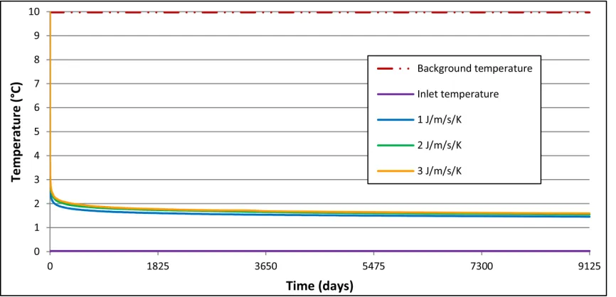
Figure 3.12 Loop outlet temperature vs. operation time for grouts with poor (1 J/m/s/K)
and average (2 J/m/s/K) thermal conductivity as well as thermally enhanced grout (3 J/m/s/K). ... 84
Figure 3.13 Loop outlet temperature vs. operation time under different background
temperatures. ... 85
Figure 3.14 Loop outlet temperature vs. time under different inlet temperatures during
operation and after abandonment. ... 85
Figure 3.15 Thermal plumes under inlet temperatures (a) +5 °C and (b) -5 °C after 1 year
showing significant difference. Note the scale difference. ... 87
Figure 4.1 The balanced and unbalanced energy loads used in the simulations. ... 102
Figure 4.2 Average fluid temperatures in various array types under the balanced energy
load and no groundwater flow. ... 104
Figure 4.3 Average fluid temperatures in various array types under the unbalanced energy
Figure 4.4 Average fluid temperatures in 4×4 square arrays with various BHE
separations, balanced and unbalanced energy loads; without groundwater flow. ... 107
Figure 4.5 Ground temperatures under balanced (left) and unbalanced (right) energy
loads with no groundwater flow after 25 years. Note the same temperature and length scales. The cross symbols (×) show the location of BHEs. ... 107
Figure 4.6 Average fluid temperatures in various array types, under the balanced energy
load and 10-7 m s-1 groundwater flow. ... 109
Figure 4.7 Average fluid temperatures in various array types, under the unbalanced
energy load and 10-7 m s-1 groundwater flow. ... 111
Figure 4.8 Individual BHE loop temperature in 4×1 and 2×2 arrays with unbalanced
energy load and 10-7 m s-1 groundwater flow. Boreholes are named a, b, c, d from
upgradient to downgradient. ... 111
Figure 4.9 Ground temperatures around 4×1 boreholes in the 25th heating season under
unbalanced load with no groundwater (left) and 10-7 m s-1 flow rate (right). Flow
direction is from bottom to top of the image. The cross symbols (×) show the location of BHEs. ... 112
Figure 4.10 Ground temperatures under balanced (left) and unbalanced (right) energy
loads, with groundwater flow (10-7 m s-1) after 25 years. Note the same temperature and
length scales. Flow direction is from bottom to top of the image. The cross symbols (×) show the location of BHEs. ... 113
Figure 4.11 Average loop temperatures in 4×4 square arrays with various BHE
separations and groundwater flow rates, under balanced energy load. ... 115
Figure 4.12 Average loop temperatures in 4×4 square arrays with various BHE
separations and groundwater flow rates, under unbalanced energy load. ... 115
Figure 4.13 Comparison of inlet and average outlet temperatures in the 4×4 BTES, under
Figure 4.14 Ground temperatures in surroundings of the BTES peaking in the 25th cycle of heat storage (top panels) and dissipating after the extraction in the end of the 25th year
(bottom panels) with no groundwater (left) and 10-7 m s-1 flow rate (right). Flow direction
is from bottom to top of the image. The cross symbols (×) show the location of BHEs. 118
Figure 5.1 Annual specific energy extraction rate function. ... 126
Figure 5.2 Temperature distribution around the BHE, 25th year (left) and fluid
temperature (right) in the reference conduction model. ... 130
Figure 5.3 Thermal plume with a 1 mm open vertical fracture at 1 m (left), 5 m (centre)
and 10 m (right) from the BHE. ... 131
Figure 5.4 BHE fluid temperatures in models with a 1 mm open fracture at 1 m, 5 m and
10 m distances from the borehole compared to a homogeneous model with no fracture. ... 132
Figure 5.5 Thermal plume with a vertical fracture at 5 m from the BHE: 0.1 mm (left), 1
mm (centre) and 10 mm (right) fracture apertures. ... 133
Figure 5.6 BHE fluid temperatures in models with 0.1 mm, 1 mm and 10 mm fracture
apertures at 5 m distance from the borehole compared to a homogeneous model with no fracture. ... 134
Figure 5.7 Temperature distribution around the BHE with two vertical fractures at 1 m
and 5 m distances, 25th year (left) and fluid temperature with fractures at 1 m, 5 m, and 1 m and 5 m (right). ... 135
Figure 5.8 Thermal plume with 1 mm open vertical fractures at 5 m: two parallel
(top-left), two perpendicular (top-right), three crossing at 90 ° (bottom-left) four crossing at 90 ° (bottom-right). ... 136
Figure 5.9 BHE fluid temperatures in models with single and multiple open fractures (1
Figure 5.10 Temperature distribution around a BHE with 10 parallel vertical fractures at 10 m spacing (frequency=0.1), BHE distance from nearest fracture=5 m, 25th year (left) and corresponding fluid temperature, plus fluid temperatures from 2 parallel fractures and 1 fracture each 5 m from the BHE and no fracture (right). ... 137
Figure 5.11 Thermal plume from 2 BHEs 10 m apart, in homogeneous media (left) and
with an open (1 mm) vertical fracture at 5 m from each BHE (right) in the 25th heating cycle. ... 138
Figure 5.12 Fluid temperatures in 2 BHEs at 10 m separation with no fracture compared
to a case in which a vertical open (1 mm) fracture is located in the middle of the BHEs at 5 m distance from each. ... 139
Figure 5.13 Thermal plume with a 50 m deep, 1 mm open horizontal fracture at 45 m
(left), 50 m (centre) and 55 m (right) from the surface. ... 140
Figure 5.14 BHE fluid temperatures with a horizontal open (1 mm) fracture intersecting
the borehole at 25 m, 50 m and 75 m depths, and no-fracture model. ... 141
Figure 5.15 Minimum grout (left) and BHE fluid (right) temperatures in the 25th year
with horizontal fractures of various apertures intersecting the borehole at 50 m depth, and 10×1 mm fractures at every 10 m. ... 142
Figure 5.16 BHE fluid temperatures with horizontal fractures of various apertures
intersecting the borehole at 50 m depths, and 10×1 mm fractures at every 10 m, compared to the no-fracture model. ... 142
Figure 5.17 Simulation thermal response test fluid mean temperatures from homogeneous
and inhomogeneous (a single vertical 1 mm open fracture at 5 m distance from the BHE) cases. ... 143
Figure 5.18 Temperature disturbance around a BHE in a homogeneous background as a
result of a hypothetical TRT after 30 days. Temperature differential at 5 m from the BHE
Chapter 1
1
Synopsis
1.1
Rationale of study
Renewable energies are becoming increasingly popular due to their near inexhaustibility, generally lower emissions and lifetime costs, higher reliability and more stable prices, compared to fossil fuels such as oil. Geothermal, defined as the thermal energy stored in the Earth, is a renewable source of energy. Conventional geothermal technology often deals with temperatures near the boiling point of water which limits its applicability to specific locations. At the lowest end of the geothermal energy spectrum, in terms of temperature, is ground source heat which utilizes energy from “normal” ground temperatures predominant across the earth. Low temperature geothermal, or ground source energy, is commonly used for space heating and cooling in buildings which makes it economically attractive to domestic and commercial consumers. Despite being
“sustainable” by nature as a renewable energy, “unsustainable” use of ground source energy can potentially cause some environmental problems, and diminish performance efficiency. A prevalent method of extracting ground source heat energy is through borehole heat exchangers (BHEs) which interact with the subsurface saturated zone, and whose performance involves both the mechanical system properties and hydrogeological aspects.
The transport of heat in the solid phase is governed by Fourier’s law which relates the specific heat flux rate to the temperature gradient and thermal conductivity, analogous to Darcy’ law. In saturated porous media, heat transport occurs through: 1) conduction in the solid phase, 2) conduction in the liquid phase, and if groundwater is flowing, 3) advection in the liquid phase and 4) hydrodynamic dispersion in the liquid phase. From the conservation of mass and energy, heat transport by the soli-fluid matrix is formulated as:
𝜕𝑇
𝜕𝑡+
𝜌𝑤𝑐𝑤
𝜌𝑐 ∇𝑇𝑞 − � 𝜆
where T is temperature, t is time, λ is the solid-water matrix thermal conductivity, α is
dispersivity, q is specific groundwater discharge, ρ is density and c is volumetric heat
capacity (w denotes the water phase). At sufficiently high groundwater flow rates, the
heat transport by advection may become more significant than by conduction, and is no longer negligible. This is often enumerated by the dimensionless thermal Péclet number
(Pe) as a rough indicator:
𝑃𝑒= 𝜌𝑤𝑐𝑤𝑞𝐿
𝜆 (1.2)
where L is a characteristic length of the model.
1.1.1
Research objectives
In brief, this thesis aims to put borehole heat exchangers in a hydrogeological context, specifically in regard to groundwater flow, and to evaluate their environmental and thermal sustainability in that perspective. Thereupon, quantifying the effect of
groundwater flow on BHEs loop temperatures and studying the behaviour of conforming thermal plumes are the main supplementary objectives. Concerns with thermal
sustainability can emerge from both internal and external factors. Within a multiple borehole geothermal system, thermal interaction between BHEs, which may or may not involve groundwater flow, can influence thermal sustainability. The inter-borehole thermal interference may depend on the thermal load of the system, i.e. heating or cooling only vs. heating and cooling vs. heat storage and reuse. Thus, this work will also asses at how the long-term sustainability of multi-borehole geothermal systems is
influenced by its energy load and groundwater flow; and how effective are the design aspects, e.g. borehole spacing. The final goal of this work is to differentiate between homogenous and heterogeneous geologies (i.e. fractured rock), thereby extending the main objective of this study to non-homogenous conditions, and to determine what fracture properties are of principal significance. Each of the four papers that comprise this thesis is intended to answer one of the above questions and is based on the findings from the previous paper and other referenced studies. Below is a short summary relating all the
details on the results from each paper are presented as a guide to prepare the reader in going through this thesis.
In most countries where the geothermal industry is still undeveloped and immature, unsuccessful application of BHEs can hurt the reputation of the technology and its development. Alternatively, areas where the geothermal business is advanced have higher failure risks due to potential negative interactions between a larger number of installations. This study begins with an assessment of the current status of the scholarly literature, design practices, and the state of the industry and regulatory framework. The review reveals that groundwater flow is a potential factor influencing the performance efficiency of BHEs as well as their adverse impacts on the environment or adjacent BHEs. Groundwater flow is routinely not incorporated in the design process, and is seldom and only vaguely covered in the regulatory environment. This is despite the fact that tools for integration of groundwater flow in modeling already exist (e.g. Diao et al. 2004; Diersch et al 2011a and 2011b; Molina-Giraldo et al. 2011). Thus, the approach taken here is to first use these tools to analyse the effect of groundwater flux along with other hydrogeological and thermal factors on a single BHE. This is an original approach to investigating these factors in the sense that they are studied within the same
framework; therefore, they can be properly compared against each other. The results rank groundwater flux among the top influential parameters. Knowing that groundwater flow is of high importance, the analysis is extended to multiple-borehole systems with various configurations. In multi-BHE systems, energy load balance (or lack thereof), which is unimportant in single BHEs, becomes relevant (Rybach and Eugster 2002; Signorelli et al. 2005; Priarone et al. 2009). This research also studies the interaction of unbalanced and balanced energy loads, including borehole thermal energy storage (BTES) systems, with groundwater flow. Lastly, the effect of hydraulic heterogeneities is considered; while the earlier parts of the research only consider homogeneous settings.
temperatures, thermal response test (TRT) results, and apparent thermal conductivity of the ground. Here, it is intended to further examine the effect of fracture properties and complexity level of fracture networks on system performance and its impact.
1.2
Thesis organization
This thesis is structured in the integrated article format. The current chapter, Chapter 1, is meant to state the significance of this research and present the thesis outline. It also puts the appended papers in the context of study aims and illustrates the course of the
research.
Chapter 2 is based on the manuscript, “Guidelines and the Design Approach for
Vertical Geothermal Heat Pump Systems: Current Status and Perspective”, currently
accepted with minor revisions in the Canadian Geotechnical Journal. This chapter starts
with a literature review on environmental and thermal sustainability of single and
multiple borehole heat exchangers in a hydrogeological perspective. Of particular interest is the interaction of such systems with groundwater flow. Several recent studies (e.g. Lee
and Lam 2009; Lazzari et al. 2010) have shown that the groundwater flux rates in the 10-7
m/s range (and above) impact the thermal response tests results (TRTs) and the performance of BHEs. Review of the software commonly used for the design of
geothermal loops reveals that they dominantly overlook the advective heat transport by groundwater flow. This is despite the existence of coupled flow-heat transport software and the recently developed analytical solutions that account for advection (e.g. Diao et al. 2004; Molina-Giraldo et al. 2011). Finally, the current state of guidelines and regulations are reviewed, few of which mention the necessity for hydrogeological investigations and modeling or provide design recommendations.
Chapter 3 includes the paper, “Effect of thermal-hydrogeological and borehole
hydrogeological circumstances with different borehole characteristics (groundwater flux, thermal conductivity of the ground, volumetric heat capacity of the ground, subsurface porosity, grout thermal conductivity, loop inlet and background temperatures), in the same modeling framework. Although various studies in the past have analyzed the effect of some of these factors individually (e.g. Hellström 1998; Chiasson et al. 2000), the main purpose of this work has been to enable us to compare them and distinguish the
principal factors affecting BHEs. The results rank groundwater flux (above 10-7 m/s) and
thermal conductivity of the ground as the top thermal-hydrogeological parameters affecting the performance and impact of BHEs. The temperature gradient between the antifreeze fluid and the ground is another key factor which implies accurate estimation of the ground temperatures to ensure a correct design. Groundwater flow clearly has a more significant role in returning the ground temperatures to the initial background
temperature, i.e. thermal recovery. Groundwater fluxes as low as 10-8 m/s can accelerate
the thermal recovery of the ground.
The manuscript submitted to the National Ground Water Association’s (NGWA) Groundwater journal, “Impact of Groundwater Flow and Energy Load on Multiple Borehole Heat Exchangers”, forms the 4th chapter. Previous studies such as Rybach and
Eugster (2002), and Signorelli et al. (2005) have studied the effect of energy load and borehole spacing on the long-term sustainability of multi-BHE systems. The energy load balance (or unbalance) becomes more relevant as the number of boreholes increases. To our knowledge, no study has evaluated the effect of groundwater flow in conjunction with energy load balance. The evaluation is done for single, 2×1, 4×1, 2×2 and 4×4 arrays. This study also examines how important the borehole spacing is in this context.
Based on the previous research a 10-7 m/s groundwater flux is assigned to models that
groundwater flow direction is parallel to the array axis. Previous studies (Choi et al. 2013) have proven that line arrays are more sensitive to groundwater flow direction than square arrays are. The borehole spacing is also more influential on the efficiency of multi-BHE systems that have unbalanced energy loads. However, increasing groundwater flow shortens the time to reach quasi-steady state significantly more than increasing the BHE spacing does. Simulations confirm that, in the long-term, an array with smaller BHE spacing in a hydraulically conductive environment can over-perform a similar system with larger BHE spacing and no groundwater flow. Lastly, a borehole thermal energy storage (BTES) system is compared with a conventional multi-BHE system with balanced load. BTES systems essentially have a balanced energy load even though the building energy demand is not balanced, as they store the energy during one season for use at another time of year. In addition, typically BTES systems involve high temperature gradients which enhance the heat exchange by conduction. For this reason, groundwater flow exhibits a negative impact on the modeled BTES by increasing the stored energy while decreasing the energy extraction. Therefore, not integrating the groundwater flow in the design procedure of BTES systems can undermine their environmental and thermal sustainability.
The last paper, “Effect of hydrogeological inhomogeneity on borehole heat
exchangers”, which is prepared for submission to the Bulletin of Engineering Geology and the Environment, the official journal of the International Association for Engineering Geology and the Environment (IAEG), adds the heterogeneity aspect to the earlier
homogenous models. The heterogeneity introduced here is in the form of fractures. Previous studies (e.g. Gehlin and Hellström 2003; Liebel et al. 2012) have proven that water-filled fractures nearby or intersecting a BHE can influence loop temperatures. This last paper aims to distinguish between heterogeneity features based on their properties and designate the principal fracture properties affecting BHEs. A BHE interacts differently with vertical and horizontal fractures. Vertical fractures can have different strikes (thus interconnect) and distances from the BHE, creating more complex
major fracture can be identified impacting the BHE based on their distance and fracture openness. The effect of vertical fractures on the BHE becomes progressively less as the distance between them increases. An open (1 mm) vertical fracture located up to 5 m away from the BHE significantly alters the loop temperatures; at 10 m distance the fracture still causes visible influence. Tight fractures (0.1 mm) have no noticeable influence but open (1 mm) and wide (10 mm) fractures will cause an obvious impact if located close enough to the borehole. While the impact increases considerably from a tight to open fracture, it increases substantially less from an open fracture to a wide one. Additionally, open fractures have the capacity to reduce the thermal inference among adjacent BHEs if passing between them. Simulations also prove that while a standard thermal response test (TRT) may not be able to detect some nearby vertical fractures, they affect the long-term efficiency of the BHE. This suggests that TRTs are less effective in such highly heterogeneous environments. In fractured rock sites, where the rock mass has more or less constant thermal properties, a TRT or perhaps simpler thermal conductivity measurement methods such as probes, could be combined with site
1.3
References
Chiasson, A.D., S.J. Rees, and J.D. Spitler. 2000. A preliminary assessment of the effects
of groundwater flow on closed-loop ground-source heat pump systems. ASHRAE
Transactions 106:380–393.
Choi, J.C., J. Park, and S.R. Lee. 2013. Numerical evaluation of the effects of
groundwater flow on borehole heat exchanger arrays. Energy 52:230–240.
Diao, N., Q. Li, and Z. Fang. 2004. Heat transfer in ground heat exchangers with
groundwater advection. International Journal of Thermal Science 43:1203–1211.
Diersch, H.J.G., D. Bauer, W. Heidmann, W. Rühaak, and P. Schätzl. 2011a. Finite
element modeling of borehole heat exchanger systems: Part 1. Fundamentals. Computers
and Geosciences 37:1122–1135.
Diersch, H.J.G., D. Bauer, W. Heidmann, W. Rühaak, and P. Schätzl. 2011b. Finite element modelling of borehole heat exchanger systems: Part 2. Numerical simulation. Computers and Geosciences 37:1136–1147.
Gehlin, S.E.A., and G. Hellström. 2003. Influence on thermal response test by
groundwater flow in vertical fractures in hard rock. Renewable Energy 28:2221–2238.
Hellström, G. 1998. Thermal Performance of Borehole Heat Exchangers. In Proceedings
of the 2nd Stockton International Geothermal Conference, 16–17 March 1998.
Lazzari, S., A. Priarone, and E. Zanchini. 2010. Long-Term Performance of Borehole
Heat Exchanger Fields with Groundwater Movement. In Proceedings of the COMSOL
Conference 2010, Paris, France.
Lee, C.K., and H.N. Lam. 2009. Determination of groundwater velocity in thermal
response test analysis. In Proceedings of Effstock 2009 conference, Stockholm, Sweden,
Liebel, H.T., K. Huber, B.S. Frengstad, R.K. Ramstad, and B. Brattli. 2012. Thermal response testing of a fractured hard rock aquifer with and without induced groundwater
flow. Bulletin of Engineering Geology and the Environment 71:435–445.
Molina-Giraldo, N., P. Blum, K. Zhu, P. Bayer, and Z. Fang. 2011. A moving finite line source model to simulate borehole heat exchangers with groundwater advection.
International Journal of Thermal Sciences 50:2506–2513.
Priarone, A., S. Lazzari, and E. Zanchini. 2009. Numerical Evaluation of Long-Term
Performance of Borehole Heat Exchanger Fields. In Proceedings of the COMSOL
Conference, Milan, Italy, 14–16 October 2009.
Rybach, L., and W.J. Eugster. 2002. Sustainability aspects of geothermal heat pumps. In Proceedings of the 27th Workshop on Geothermal Reservoir Engineering, Stanford
University, CA, USA, 50-64.
Signorelli, S., T. Kohl, and L. Rybach. 2005. Sustainability of production from borehole
Chapter 2
2
Guidelines and the Design Approach for Vertical
Geothermal Heat Pump Systems: Current Status and
Perspective
2.1
Introduction
Shallow low temperature geothermal (alternatively called ground source, ground coupled, geoexchange and earth energy) systems utilize normal ground temperatures and are generally used for space heating and cooling. This temperature range allows such systems to be used worldwide. These systems rely on the nearly constant temperature of the subsurface throughout the year. Fluctuations in ground temperature decrease with depth (Rosén et al. 2001, Banks 2008) due to the high thermal inertia of the soil, the time lag between temperature variations at the surface and in the subsurface (Florides and Kalogirou 2007) and the upward geothermal flux from Earth’s center. Seasonal temperature variation diminishes below the depth of ca. 10 m according to Anderson (2005). The exact depth depends on the ground thermal properties, varying from 8 m for dry light soils to 20 m for moist heavy sandy soils (Popiel et al. 2001). Temperatures at such depths are similar to the average ambient air temperature over the year (Ochsner 2007). The ground temperature above this depth is affected by land cover (Ferguson and Woodbury 2007) and weather (Zhang 2005, Florides and Kalogirou 2007). As in
summer/winter the subsurface temperature is respectively lower/higher than the air temperature, the ground source heat can be employed to cool/heat the buildings.
the commonly used polyethylene pipe (diameters/frictional losses) and drilling costs. In Switzerland installations to a depth of 500 m using 50 mm diameter polyethylene pipe have been reported. If long borehole lengths are required, it is more feasible to use multiple boreholes to avoid deep drilling/installation complications and increase the energy extraction area as closed loops function only on conduction.
Closed loop ground heat exchangers are alternatively termed as ground coupled heat exchanger (GCHE) and ground source heat exchanger (GSHE); specifically vertical closed loops also are known as borehole heat exchanger (BHE). Since ground heat
exchangers should effectively exploit the ground heat for long periods of time due to their high initial installation cost, they should have good thermal properties and durability. Highly durable and flexible polyethylene and polypropylene are typically used in
production of ground heat exchangers. Most borehole heat exchangers consist of U-pipes, with a U-turn in the end creating a loop: single U-pipe (e.g. common in Canada and Sweden) or double U-pipe when two U-pipes are inserted in the borehole (e.g. common in Germany and Switzerland). The other, less common, type includes coaxial pipes or concentric heat exchangers. Depending on the direction of the flow this type of heat exchanger can be with annular (CXA) or centered (CXC) inlet (Diersch et al. 2011a). Schematics of different heat exchangers are shown in Figure 2.1.
Figure 2.1 Schematics of U, 2U and coaxial borehole heat exchangers. Grey color
A circulating fluid or heat transfer fluid, usually a water-antifreeze mixture, is used to extract the heat and transport it in the system. An antifreeze is evaluated based on factors like thermal properties, viscosity and lifetime pumping costs, toxicity,
biodegradability (aerobic and anaerobic), biological oxygen demand (BOD), corrosivity and flammability (refer to Heinonen et al. (1997, 1998) for more details).
The gap between the BHE and the borehole wall, i.e. annulus, is usually filled with grout. This reduces the thermal efficiency of the BHE but protects the groundwater from antifreeze leakage, introduction of contaminants from the surface, and
interconnected aquifers. For example, improper grouting in Staufen im Breisgau, Germany exposed a anhydrite sulphate calcium layer to water; causing damage to more than 250 houses (Oriol 2010 after Therin 2010). In North America and most parts of Europe the annulus is grouted (Andersson 2007, Denicer and Rosen 2007) while under
certain geological conditions, like in parts of Scandinavia (e.g. Sweden’s Normbrunn
-07), grouting is not required and the boreholes are naturally filled with groundwater
leading to increased thermal efficiency of the system and extended borehole life. The not-grouting practice has other long-term economic benefits by making the borehole reusable beyond the life of the loop pipes. However, this is possible due to the presence of
hardrock geology with minor soil cover. When grouting is to be done, using thermally enhanced grout is recommended due to its lower thermal resistance.
The simplest technique for using ground source heat is to circulate the heat exchanger fluid in the building, called free or passive cooling/heating. However, geothermal heat pumps (GHPs) are normally used in conjunction with BHEs, to lift or sink the gained temperature differential by using electric power. Geothermal heat pumps are also called ground source heat pump (GSHP) and ground coupled heat pumps
(GCHP).
storage (ATES) systems thermal energy is stored in the groundwater and in the soil/rock matrix through an open loop. Borehole thermal energy storage (BTES) is a UTES practice using a number of densely spaced closed loop BHEs.
2.2
Aim of Study
This study begins with a brief review on the state of research on the sustainability of geothermal heat pump systems with concentration on the thermal and thermally driven environmental issues. The main purpose of the literature review is to address the
influence of groundwater flow on geothermal systems and identify any known thresholds where advective heat transport is no longer negligible. The available loop design tools which are commonly used by the industry will be explored. Furthermore the method employed by design software is examined particularly with regards to assumptions on groundwater flow. Finally the current state of regulations is reviewed, and the potential for integrating the groundwater flow in vertical geothermal systems is considered. Since open loops involve the extraction of groundwater and have potentially larger
environmental implications, typically they require more intensive hydrogeological evaluations and trigger more regulatory provisions. On the other hand, closed systems often fall outside the typical groundwater regulatory environment. They also are often designed without consideration of groundwater advection. Thus while open loop systems are covered in this paper for comparison, the focus is on closed loop systems.
As the following review will show, under certain conditions where groundwater flow rate is sufficiently high, a lack of consideration for groundwater advection can lead to considerable difference between actual and designed system performances. Although comparable reviews have been done on the state of regulations (e.g. Haehnlein et al. 2010) or design (e.g. Hellström and Sanner 2001), this paper attempts to bring the legislation, design tools and knowledge aspects together and point out the deficiencies in that context. Recognition of the role groundwater plays in thermal design and
an international perspective and increasing the awareness among the associated Canadian authorities and professionals.
This work does not address if the cited information is legally enforced or only voluntary. Thus the use of terms such as recommendation, guideline, standard, regulation and legislation are intended to reflect the proper context but may not in all cases.
2.3
Design and environmental-thermal sustainability in
a hydrogeological context
Historically major concerns with geothermal heat pump systems involved the mechanical components and design, energy efficiency, and cost. However, recently their interaction with subsurface processes and protection of underground resources, chiefly groundwater, is receiving increasing attention. Concerns about GHPs are not only environmental, but also include thermal performance and sustainability of the system (Ferguson and
Woodbury 2005, Hecht-Méndez et al. 2010). Although some of the impacts are similar to those involving water wells, this work focuses on thermally driven subsurface impacts including impacts on adjacent systems. While heat can be recognized as pollution (e.g. European Water Framework Directive), with the exception of a few countries, current standards and regulations do not address thermal pollution.
Geological material, through their thermal properties, influence the performance of ground coupled systems. Saturation of porous media by groundwater – not flowing – improves its thermal properties as the air is replaced by water. Groundwater hydraulics also affects the thermal functionality of a system as groundwater flow can significantly
alter heat transport. Andrews (1978) was one of the first to study “The Impact of the Use
of Heat Pumps on Ground-Water Temperature”. Heat anomalies can have physical (Schincariol and Schwartz 1990, Kolditz et al. 1998, Hecht-Méndez et al. 2010),
chemical (Sowers et al. 2006, Renac et al. 2009) and biological (York et al. 1998, Gordon and Toze 2003, Sowers et al. 2006, Markle and Schincariol 2007, Brielmann et al. 2009) impacts. These aspects can be interrelated; Banks (2008) discusses the effect of
can also affect the biology of groundwater directly or through its aquatic chemistry which
can in turn influence the physical hydrogeology in extreme cases (VDI 4640 Part3).
Since the early 20th century many models have been developed that are used to simulate borehole heat exchangers by authors such as Allen (1920), Ingersoll et al. (1950, 1954), Carslaw and Jaeger (1959), Eskilson and Claesson (1988), Hellström (1991), Kavangaugh (1992), Zeng et al. (2002), Al-Khoury et al. (2005), Lee and Lam (2008) and Zhongjian and Maoyu (2009). The results presented by Hellström (1998) and Acuña and Palm (2009) indicate that in-borehole setup (i.e. pipe configuration and fill) have significant impact on borehole thermal resistance. The impact of proximal systems on each other is multiplicative in terms of thermal efficiency. For example in Lyon, France, multiple open loop systems have increased the groundwater temperature by 3-4 °C, where each system is believed to have 1 °C impact; in a likely and plausible future scenario, groundwater temperature may exceed 25 °C resulting in non-potable water and conflicts in use (Oriol 2010). Ferguson and Woodbury (2006, 2007) show that urban and geothermal development can cause a large scale subsurface temperature increase. Similar phenomena can happen with closed loop systems (e.g. Signorelli et al. 2005) and requires concern.
Kavanaugh and Calvert (1995) and Kavanaugh and Rafferty (1997) suggest equations and correction factors applicable to different load cycles, grids and borehole separations. All the above cited studies assume the absence of groundwater flow. Chiasson (1999), Spitler et al. (1996) and Austin et al. (2000) show that increasing groundwater velocity increases effective ground thermal conductivity. One common method to measure the ground apparent thermal conductivity is a thermal response test (TRT). Traditionally the analysis of TRT results has been done assuming heat transport by conduction only. However studies such as Wagner et al. (2013) have extended the applicability of
advection influenced TRT beyond a Darcy velocity of 0.1 m/day (1.15×10⁻⁵ m/s).
Although performing a conventional TRT accounts for groundwater advection in estimating the apparent thermal conductivity, not including the flow rate and direction makes it impossible to accurately model the interaction between BHEs in a field as well as adjacent fields. Research by Gehlin (2002) concludes that groundwater flow changes temperature in and around a borehole in fractured as well as porous media. Diao et al. (2004) developed an analytical solution for a line heat source in an infinite medium which accounts for groundwater advection. Their results showed that advective transport by groundwater may alter the temperature distribution, lower temperature disturbances and eventually allow for the reaching of steady state conditions compared to a conductive dominated regime. According to a similar study by Fuji et al. (2005), Péclet numbers higher than 0.1 enhance the heat extraction rate. Lee and Lam (2009) observed and
estimated the influence of groundwater velocity on TRT results at velocities over 2×10⁻⁷
m/s. Numerical modeling of two arrays of three and six BHEs by Lazzari et al. (2010)
concludes that a groundwater velocity of 10-7 m/s suffices to stabilize the loop
temperatures after a few years. Dehkordi and Schincariol (2013) found that groundwater
fluxes above 10-7 m/s and 10-8 m/s to have a noticeable impact on improving the BHE
Groundwater flow can make a BHE system more efficient, requiring a shorter heat exchanger and allowing for a longer sustainable heat extraction period by enhancing heat transfer (Wang et al. 2012). Groundwater flow is particularly undesirable for
underground thermal energy storage (UTES) systems (Bauer et al. 2009). Some of the common “loop design” software (Table 2.1) include the thermal properties of the ground
but usually exclude the groundwater movement (e.g. EED, GLHEPRO and
GeoAnalyser). Therefore current designs may not always be optimal. In a dynamic hydrogeological environment, the shape and transport of the heat plume may be less understood, and the impact on adjacent systems is more uncertain. Coupled groundwater flow and heat transport models are available (Table 2.1) but are more commonly used for flow and transport studies and not the design of BHEs. However, some studies such as Nam et al. (2008) employed groundwater coupled models instead of those based solely on conduction.
2.4
International status of the related guidelines
Forty years ago only 10 countries were using geothermal energy in any form but today that number has increased to 80 and expected to increase to 90 by 2015 (Lund and Bertani 2010). Studies show an increase in the use of GHP systems, especially in the EU and US, even in regions with low potential for conventional geothermal resources (Freeston 1995, Lund and Freeston 2000, Sanner et al. 2003, Lund et al. 2004, Banks 2008). It is one of the fastest growing renewable energy forms; with an average annual growth of more than 10% (Bertani 2005, Curtis et al. 2005, Lund et al. 2005).
At the international level virtually no mandatory guidelines exist. Guidelines such as “Closed-loop/Geothermal Heat Pump Systems – Design and Installation Standards” by the International Ground Source Heat Pump Association (IGSHPA 2010) or some of the better national standards available (to be discussed later in this paper) may become accepted or simply followed by professionals in countries which do not have their own
Table 2.1 Typical computer codes used in geothermal systems. Mainly after:
Hellström and Sanner (2001)*, Anderson (2005)†, EU Commission SAVE
Programme & Nordic Energy Research (2005)‡, Hecht- Méndez et al. (2010)§, Yang
et al. (2010a)||.
Heat transport Loop design UTES design
AST/TWOW § CLGS * AST ‡
BASIN2 †§ DIM * ConFlow ‡
COMSOL Multiphysics (formerly FEMLAB) §
Acuña and Palm (2009), Priarone et al. (2009)
ECA * COSOND/NUSOND/TRAD ‡
FEFLOW †‡§ EED *‡|| DST ‡
FRACHEM § GchpCalc *|| EED
FRACture § GeoAnalyser
(by CGC) FEFLOW
GeoStar || GEOCALC * GHS ‡
GeoSys/RockFlow § GeoDesigner
(by Climate Master) HB-MULTIFIELD ‡
HEATFLOW †§ GLHEPRO *|| MODFLOW ‡
HEAT2, 3
Blomberg (1996) GL-Source * HST2D/3D
HST2D/3D †‡§ GS2000 * PIA12‡
HydroGeoSphere (based on
FRAC3DVS) § INOUT * PHREEQM-2D ‡
HydroTherm § Right-Loop * SBM
HYDRUS 2D/3D § TFSTEP * SHEMAT
ParFlow § WFEA * SmartStore ‡
SBM *‡ SPREADSTO-1 ‡
SEAWAT § TECOCLAY ‡
SHEMAT †‡§ THETA
SUTRA †§ TOUGH2
THETA ठTRADIKON-3D
TOUGH2 †‡§ TRNSYS-DST, TRNAST, EWS,
SBM *‡
TRADIKON 3D ‡§ TWOW ‡
TRNSYS with DST-module ‡
European standard for the design of heat pump systems) only provide a minimum framework because of the geological and climatic disparities, and heating and cooling traditions, that exist between the countries. For instance in Europe most systems are often undersized and designed for base heating load while the peak load is supplied by
alternative sources (Curtis et al. 2005, Sanner and Boissavy 2007); whereas in the US systems are designed for peak cooling load and oversized for heating (Banks 2008, Lund and Bertani 2010). Nevertheless, European standards are valuable in that they provide a general framework to guarantee at least a basic level of quality assurance in the European countries. On this basis, domestic standards for each country can be developed based on the local conditions. In many countries installation of open loops lie under water well regulations, while closed loops are not regulated because they do not extract water from the subsurface; in other cases there may be exclusive legislations for closed and open systems (e.g. Denmark) or both water and energy wells can be covered under similar regulations (e.g. Sweden).
In countries that have established regulations on the thermal use of the shallow subsurface, common control mechanisms to minimize adverse impacts include defining limits for the borehole depth; distance between boreholes; distance to: drinking water extractions, potential contamination sources, property borders, buildings, roads, and pipelines. In some cases temperature limits are also defined: absolute minimum and maximum subsurface temperature, temperature difference from the altered and natural background temperatures, inlet and outlet temperatures. Some guidelines provide
instruction on specific heat extraction and probe length design (e.g. Swiss AWP T and
German VDI 4640, ASHARE) to ensure a minimum level of sustainability (Table 2.2).
Table 2.2 Allowable heat extraction rates under German and Swiss regulations based on soil type, moisture content and full load operation hours per year.
Loop type Underground conditions Specific heat extraction
Reference
1800 hr/yr 2400 hr/yr >2400 hr/yr
VDI 4640 G erma ny Vertical <30 kW, heating only
Poor underground (dry sediment)
λ < 1.5 W/(m.K) 25 W/m 20 W/m
100-150 kWh/m per year Normal rocky underground and
water saturated sediment
λ < 1.5–3.0 W/(m.K) 60 W/m 50 W/m
Consolidated rock with high thermal conductivity
λ > 3.0 W/(m.K) 84 W/m 70 W/m
1800-2000
hr/yr Remarks
Sw itzerl an d Vertical <30 kW, heating only
Saturated strata (λ > 3 W/(m.K) 80 W/m
Plants with more than three boreholes have a lower withdrawal performance.
Bivalents or other plants with
high annual periods (> 2000 hours) have a lower extraction capacity (W/m); max 80-100 kWh/m
Lower efficiency in mountain regions
30 W/m cooling capacity
AWP-T
Rock and moist soil (λ > 2
W/(m.K) 50-55 W/m
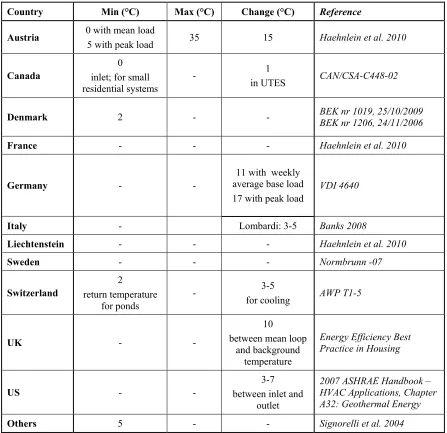
Table 2.3 Temperature thresholds of vertical closed loop geothermal systems.
Country Min (°C) Max (°C) Change (°C) Reference
Austria 0 with mean load
5 with peak load 35 15 Haehnlein et al. 2010
Canada inlet; for small 0
residential systems -
1
in UTES CAN/CSA-C448-02
Denmark 2 - - BEK nr 1019, 25/10/2009 BEK nr 1206, 24/11/2006
France - - - Haehnlein et al. 2010
Germany - - average base load 11 with weekly
17 with peak load VDI 4640
Italy - Lombardi: 3-5 Banks 2008
Liechtenstein - - - Haehnlein et al. 2010
Sweden - - - Normbrunn -07
Switzerland return temperature 2
for ponds -
3-5
for cooling AWP T1-5
UK - -
10 between mean loop
and background temperature
Energy Efficiency Best Practice in Housing
US - - between inlet and 3-7
outlet
2007 ASHRAE Handbook – HVAC Applications, Chapter A32: Geothermal Energy
Table 2.4 Distance thresholds for vertical closed loop geothermal systems. Co unt ry Aus tria Ca na da
China Czech Republic Denm
ark Finla nd Fra nce G erm any G reec e Sweden Swit zerla nd UK USA O the rs Dia m et er - - - - - - - - - - - M is sour i: de pe nds on pi pe and gr out New J er sey : b or eh ole diam eter =in ner tu be diam eter +o uter tu be diam ter e+4 " NGW A: d ep en den t o n d ep th Dept h - >5 m re gul at ed by O . R eg 98/ 12 - - - - <1 00 m an d th e m ax im al h eat rate is <232 kW , e xe m pt fr om pe rm it but a declar atio n still ne ed ed fo r >1 0 >100 m a nd/ or la rge r t ha n 232 kW , au th or iz atio n r eq uir ed - - - - - M is so ur i: 3 -70 m (d eep er th an 1 0' ar e r eg ulated an d deep er th an 2 00 ' ar e n ot n or m ally allo wed ) B et ween bo reho le s -
3-6 m -
20 m - -
in or de r t o us e gui de line for <30kW he at ing 5 m for 40 -5 0 m d eep 6 m for 50 -100 m de ep - 20 m (i n r oc k) 5-8 m 3-5 m ASHR AE : 4 .5 -8 m ( pr ovi de s m /kW ba se d on heatin g/co olin g lo ad , p lu s ad ditio nal co rr ectio n facto rs fo r d iff er en t g rid s) NGW A: 6 m (2 0') Sig ner
olli et a
l.2
00
5
: 15 m
(no seas on al r ech ar ge) O ri ol 2010 : 10 m Pr iar one 200 9
: 6 m
(4 bor ehol es with 5 0% seas on al r ech ar ge o r in fin ite b or eh oles with co m plete seas on al r ech an rg e) O chs ne r 2007 : 5 m T o r oad s - - - - If o uts id
e a city
p lan : 60 m fr om the m ot or w ay 45 m fr om th e n ati on al r oad 20 m fr om pr ovi nc ia l r oa d 6 m fr om m uni ci pa l r oa d - - - - T o nex t pro pert y 2.
5 m - 5 m -
10 m -
Hes sen : 5 m Sch les wig -Ho ls tein : 6 m -
10 m 3-4 m
M as sach us ett s: 3 m (10' ) NGW A: 6 m (20' ) To building
- - - - 3 m - 2 m - 4 m -
1.
5 m -
Table 2.5 Distance thresholds for vertical closed loop geothermal systems (continuted). Co unt ry Aus tria Ca na da
China Czech Republic
Denm ark Finla nd Fra nce G erm any G reec e Sweden Swit zerla nd
UK USA Others
T o drinking wa te r wells - - - 300 m (50 m fr om ow n water su pp ly ) 20 m (dug) 40 m (bor ed) - - - 20 m (i n s oi l) 30 m (i n roc k) - - Ill inoi s: 70 m (200' ) 75 ' f ro m o wn w ate r well ) M as sach us etts : 1 5 m (5 0') M is sour
i: 15 m
(50' ) O ri ol 2010
: 6 m
(non
-publ
ic
), 30 m
(publ ic ) T o s urf ace wa ter bo
dies - - - - - - - - - -
M as sach us etts : 30 m (10' ) M as sach us etts : 30 m (100' ) fr om wetlan ds need p er m it - T o wa st e, sewa ge and o ther co nt am ina nt so urces - - - - 30 m (20 m if ons ite ) - - -
30 m - -
NGW A: 3 -30 m (10' , 25' or 100' de pe ndi ng o n c ont am ina tion) M as sach us etts : 7 .5 m (2 5') M is sis sip pi: 3 0 m (with in 1 00 ' m us t b e gr out ed) M is so ur i: 1 5-100 m (50' , 100' or 300' de pe ndi
ng on t
he c ont am ina tion) O ri ol 2010 : 6 m to fa cilit ies , pipel ines and po werlines
- - - - 5 m -
col
d pa
rt 0.
7 m f
Table 2.7 Temperature thresholds of BHE and open loop geothermal systems.
Country Open loop Reference
min (°C) max (°C) change (°C)
Austria 5 20 6 Haehnlein et al., 2010
Canada inlet; for small 5
residential systems - - CAN/CSA-C448-02
Denmark 2 25
20 with monthly average - BEK nr 1019, 25/10/2009 BEK nr 1206, 24/11/2006
France - - 11 Haehnlein et al., 2010
Germany 5 20 6
between inlet and outlet
VDI 4640 blatt 1 VDI 4640 blatt 2 VDI 4640 blatt 3 VDI 4640 blatt 4
Liechtenstein - - 1.5-3 Haehnlein et al., 2010
Netherlands 5 25 Haehnlein et al., 2010
Switzerland 4
return temperature -
3-5 for cooling
2.4.1
Austria
Use of ground heat systems was initiated in 1976; steadily increasing since late 90’s with a tremendous growth rate of 37.7% in 2005-2006 numbering to 49,600 (Ground Reach 2008). Austrian standards directly applicable to GHPs in the context of this paper are ÖNORM M 7755-1 on general requirements, ÖNORM M 7755-2 on ground, groundwater
and surface water systems and ÖWAV RB 207 on thermal use of groundwater and
underground heating and cooling.
2.4.2
Belgium
In Belgium knowledge of GHP systems is low and this has hindered development of the
technology according to Ground Reach (2008) who state: “A great barrier for
GCHP-systems consists in the lack of knowledge of these GCHP-systems…. HVAC installers consider heat pumps as a difficult technology”. Belgium requires a drilling permit for vertical open and close loop systems (Ground Reach 2008). The Belgian standard, environmental
legislation VLAREM, was changed in September 2011 in regards to the construction of
vertical boreholes (VITO 2013) prior to which geothermal boreholes deeper than 50 m required a permit (DOV 2013a). The updated legislation makes the depth criterion location dependent; online maps are provided to find the appropriate depth criterion in Vlaanderen (Flanders) region (DOV 2013b).
2.4.3
Canada
In Canada, GHPs are the main source of geothermal energy (Lund and Bertani 2010). According to the Canadian GeoExchange Coalition (CGC) (2010a), during the early 90’s more than 7000 residential units were installed in Canada; the annual number of installed units hit a 20 year historic low in 1998. Between 2004 and 2008 the ground source heat pump market has grown by 50% annually. A strong factor in this growth is likely
from CGC (2011), which tracks mostly domestic installations, horizontal loops dominate Canadian installations at around 56% while the share of vertical loops is 24% between 2008 and 2010. The statistics for Ontario are 65% and 15%, respectively, during the same period.
Currently there are no specific federal laws on subsurface heat extraction. While
provinces maintain jurisdiction over natural resources (Canadian Constitution Act) there
are instances where existing federal legislation could affect geothermal energy resource development. For example, if a GHP impacted fish or fish habitat, then provisions of the
federal Canadian Fisheries Act or the federal Canadian Species at Risk Act would apply.
At the provincial level changes have been underway in many provinces to amend their groundwater and wells acts to better address geothermal installations. Ontario has legislation that governs GHPs, or Earth Energy Systems as they are commonly referred
to, both indirectly and directly. The Ontario Water Resources Act (OWRA) does not
specifically mention GHPs, but as open loop systems are water wells they fall under OWRA Regulation 903 which covers all aspects of well construction, permitting,
abandonment, and contractor/technician licencing. Often installers of BHEs were not as qualified to handle difficult drilling conditions (e.g. artesian aquifers, blowouts) and major environmental or human impacts can occur. Such was case in Ontario when an installer of a vertical closed loop geothermal system hit a natural gas pocket at a depth of
approximately 165 m. Ontario responded by developing Ontario Environmental
Protection Act O. Reg. 98/12 which became law as of May 18, 2012. Under O. Reg. 98/12 an Environmental Compliance Approval under section 9 of the Ontario
Environmental Protection Act is required for any vertical closed loop geothermal system that extends more than 5 m below ground surface. The application for environmental compliance approval must be prepared by a licensed engineering practitioner or
professional geoscientist. In British Columbia, as of 2005, closed loop geothermal wells
are covered in the Ground Water Protection Regulation under the Water Act from