1824 |
P a g e
Design and Implementation of Compact Booth Multiplier
for Low power, Low Area & High Speed Applications
1
M.Sivakumar,
2S.Omkumar
1
Research Scholar,
2Associate Professor, ECE Department, SCSVMV University, Kanchipuram,
ABSTRACT
Presently, the design of a compact multiplier is playing a vital role in the stream of VLSI signal processing, DSP, Modern wireless communication etc. The main goal of this proposal is to design a compact booth multiplier by using modified radix4 recoding and an efficient finite state machine (FSM) to achieve small chip size and low delay utilization. In the existing technique, compression based booth multiplier is designed by using carry look ahead adder, multiplexer, booth encoder and partial product generator (PPG). It requires more resource utilization (area) and the performance characteristics is very less in the existing booth multiplier. To come up with a solution to this problem, modified radix4 algorithm with an optimized FSM design is used to construct the compact booth multiplier. Simulation and synthesis is performed by applying the ModelSim and Xilinx 13.1 based on Verilog HDL. FPGA spartan6 LX9 board is used for implementation.
Key Words: Modified radix4 recoding, FSM, FPGA spartan6 LX9, Verilog HDL and proposed
booth multiplier.
I. INTRODUCTION & RELATED WORK
The multiplier design is mostly classified into two types which is signed and unsigned multiplier. In the signed
multiplier it will perform both positive and negative multiplication. But in the unsigned multiplier is used to
imply only positive number of multiplication. For example, Vedic multiplier, Wallace multiplier, parallel
multiplier etc are unsigned multiplier. From that booth multiplier is the one among the signed multiplication
scheme. In the current techniques, radix2, radix8 and radix16 based recoding is carried out to design a booth
multiplier. The existing multiplier gives out high complexity, high area and low speed. The proposed booth
multiplier contains only 2 blocks such as FSM and radix4 recoding technique.
For generation of recoded multiplier of radix2, following steps are to be performed.
i) Append the given multiplier with a zero to the LSB side.
ii) Make group of two bits in the overlapped way recode the number by looking into the table below.
Table: 1 Radix 2 Recoding Rule
Qn Qn+1 Recoded Bits Operation
Performed
0 0 0 Shift
0 1 +1 Add M
1 0 -1 Subtract M
1 1 0 Shift
1825 |
P a g e
i) The Number of addition/subtraction operations and the number of shift operations is variable and becomes
inconvenient in creating a design for parallel multiplier.
ii) The algorithm becomes inefficient and obsolete when there are isolated 1’s.These limitations are rectified
by using the Modified Radix 4 Recoding technique.
For example 001010101(0) recoded as 011111111, requiring 8 instead of 4 operations. Consider 3 bits at a time.
Overlapping form with the previous bits which starts from the LSB. The overlapping bits shown below.
0 1 0 1 1 0 1 0 1 0
Table: 2 Modified Radix 4 Multiplier
Block of 3 bits Partial Product
000 0
001 1*Multiplicand
010 1*Multiplicand
011 2*Multiplicand
100 -2*Multiplicand
101 -2*Multiplicand
110 -1*Multiplicand
110 -1*Multiplicand
111 0
In the usual and existing technique, it contains modified booth encoder, multiplexer, PWR for equality checking,
partial product generator (PPG), compressor based Carry Look Ahead adder (CLA) and D flip-flops. Encoding
is performed by using booth encoder. Multiplexer is used for choosing any one of input for encode. After that
partial product is obtained by using two inputs. Then compression based carry look ahead adder is used to
condense the partial product accumulation stages. First, second and final stages are used for compression by
using these three stages. Compressor based booth multiplier is used to achieve high speed than the all other
traditional technique. But the complexity is extremely high. But the area and power is very high. A new booth
multiplier is designed in the proposed scheme further to enhance the speed of the booth multiplier. To refrain
from this kind of problem, the current booth multiplier structure is modified by bringing forth a new finite state
machine in order to achieve low area, low power and high speed. Fig.1 shows the technology, block diagram
and RTL schematic of existing booth multiplier.Fig.2 shows the Device utilization summary report for area
calculation of existing booth multiplier. Fig.3 shows the Timing constraint summary report for delay calculation
of existing booth multiplier.
1826 |
P a g e
Fig.2 Device Utilization Summary report of existing booth multiplier
Fig.3 Timing constraint report of existing booth multiplier
II. PROPOSED BOOTH MULTIPLIER
The proposed booth multiplier consists of finite state machine (FSM) and modified radix4 booth recoding
technique to perform the multiplication of two numbers as shown in fig.4. The number of shift and add is very
low in the proposed booth multiplier. Also the partial product accumulation stage is reduced in order to shrink
the complexity of the proposed multiplier. In the radix4 recoding technique perform X, 1X and 2X. Shift,
addition and subtraction are carried out to perform the sign multiplication based upon the booth multiplier.
Fig.4 Block diagram of proposed booth multiplier
Generally, the Finite State Machine (FSM) is classified into two types such as Mealy FSM and Moore FSM.
Moore FSM is synchronous and mealy FSM is an asynchronous logic. Also the number bit is equal to the
number of state in mealy FSM. But the Moore FSM requires one more state than the mealy. Fig.6 shows the
block diagram of the technology and RTL Schematic of optimized new FSM Based proposed booth multiplier.
Finite State Machine
Modified Radix 4 Recoding Technique
1827 |
P a g e
“Next State” “State update” “Output”
Fig.7 shows the summary report of the device’s utilization for area calculation of the proposed booth multiplier.
Fig.8 shows the timing constraint summary report for delay calculation of proposed booth multiplier. Fig.8
shows the state diagram of proposed optimized booth multiplier by using add and shift method.
Finite State Machine implementation in Verilog:
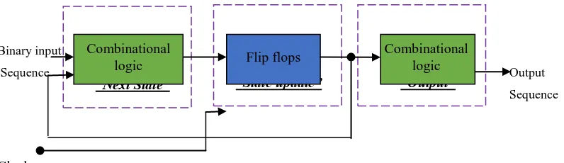
Fig.5 shows the block diagram of Moore FSM.VHDL is one of the frequently employed techniques for the
digital system’s emergent process. This technique is achieved by using a program from a certain software which
performs simulation and examination of the designed system. Verilog does not define a standard way of
describing a finite state machine (FSM). A good way to specify a Moore type FSM is to use separate procedural
blocks for the “Next state” combinational logic for the “state update” sequential logic and for the “output”
combinational logic as suggested by the block diagram of a Moore FSM.
Binary input
Sequence Output
Sequence
Clock
Fig 5. Block diagram of a Moore FSM
Verilog code for Moore type FSM:
//Detects input sequence with overlap
module boothrecodemul8(
iClk,iReset_b,iGo, oDone, iMer, // 8-bit multiplier
iMand, // 8-bit multiplicand
oProduct);
input iClk,iReset_b,iGo; input [7:0] iMer,iMand;
output reg oDone;output [15:0] oProduct;
// State names assignment (local parameter)
Parameter WaitForGoState = 0, InitState = 1, AddShiftState = 2, DoneState =3;
reg [1:0] PresentState, NextState; reg [1:0] NumShifts; reg [18:0] Product; reg [9:0] Sum;
//Define “Next state” Combinational logic (main FSM controller for next state logic)
always @(iGo,PresentState,NumShifts)
begin: Controller
case (PresentState)
WaitForGoState: if (iGo) NextState <= InitState; else
NextState <= WaitForGoState;
InitState: NextState <= AddShiftState;
AddShiftState: if (NumShifts == 2'b00)
NextState <= DoneState; else
NextState <= AddShiftState;
DoneState:
NextState <= DoneState; default: NextState <= InitState; endcase
// PresentState
end
Combinational
logic Flip flops
1828 |
P a g e
//Define “output” Combinational logic (Output assignments)
assign oProduct = Product[16:1];
always@(*) begin
if(PresentState==DoneState)
oDone<=1; else
oDone<=0;
end
endmodule
Fig.6 Technology Block diagram & RTL schematic of FSM based proposed compact booth multiplier
Fig.7 Device Utilization Summary report of proposed compact booth multiplier
Fig.8 Timing constraint report of proposed compact booth multiplier
III. RESULTS & DISCUSSION
The design of existing and proposed booth multiplier is designed using Verilog hardware description language
(HDL) for register transfer level (RTL) process. These two types of multiplier are designed and implemented in
field programmable gate array (FPGA) Spartan6 LX9 board. Simulation is carried out by ModelSim and
1829 |
P a g e
(UCF) is done to assign the input and output pin in the FPGA board. Finally, the bit file is generated to dump
the Verilog program on the FPGA board. Table 1, 2 and 3 shows the comparison between existing and proposed
booth multiplier is performed to analyze the area, delay and power (ADP) product.
Fig.9 Area utilization Comparison between Existing & Proposed Compact Booth multiplier with FSM
Fig.10 Delay Comparison between Existing & Proposed Compact Booth multiplier with FSM
Fig.11 Power Comparison between Existing & Proposed Booth multiplier with FSM
In the Proposed method, active high reset is employed in the design of the booth multiplier. So when the reset is
low, the output is zero. Otherwise the product of two numbers is given as output when the signal which is done
goes high. For example, multiplicand is -61 and multiplier is 51are given as inputs of the multiplier. The
corresponding multiplication output is obtained as -3111 as shown in fig.12.
1830 |
P a g e
The sample data input and output calculation for existing booth algorithm versus proposed booth multiplier is
given below.
a. Sample data Calculation using proposed Compact Booth Multiplier
A
0 0 1 1 0 0 1 1 51
X x 1 1 0 0 0 0 1 1 -61
Y
0 -1 0 0 0 1 0 -1 recoded multiplier
Add -A + 1 1 1 0 0 1 1 0 1
2-Bit Shift 1 1 1 1 1 0 0 1 1 0 1
Add A + 0 0 0 1 1 0 0 1 1
0 0 0 1 0 0 1 1 0 0 1
2-Bit Shift 0 0 0 0 0 1 0 0 1 1 0 0 1
2-Bit Shift Only 0 0 0 0 0 0 0 1 0 0 1 1 0 0 1
Add -A + 1 1 1 0 0 1 1 0 1
1 1 1 0 0 1 1 1 1 0 1 1 0 0 1
2-Bit Shift 1 1 1 1 1 0 0 1 1 1 1 0 1 1 0 0 1 -3111
b. Sample data Calculation using existing Booth Multiplier
A 0 0 1 1 0 0 1 1
51
X x 1 1 0 0 0 0 1 1
-61
Y 0 -1 0 0 0 1 0 -1
recoded multiplier
Add –A + 1 1 0 0 1 1 0 1
Shift 1 1 1 0 0 1 1 0 1
Shift Only 1 1 1 1 0 0 1 1 0 1
Add A + 0 0 1 1 0 0 1 1
0 0 1 0 0 1 1 0 0 1
Shift 0 0 0 1 0 0 1 1 0 0 1
Shift Only 0 0 0 0 1 0 0 1 1 0 0 1
Shift Only 0 0 0 0 0 1 0 0 1 1 0 0 1
Shift Only 0 0 0 0 0 0 1 0 0 1 1 0 0 1
Add -A + 1 1 0 0 1 1 0 1
1 1 0 0 1 1 1 1 0 1 1 0 0 1
Shift 1 1 1 0 0 1 1 1 1 0 1 1 0 0 1
Shift Only 1 1 1 1 0 0 1 1 1 1 0 1 1 0 0 1 -3111
1831 |
P a g e
Table.3 Comparison between existing & proposed booth multiplierTypes Slices (area) LUT Delay (ns) Power (mW)
Existing Booth Multiplier 44/1430 104/5720 3.597 651
Proposed Compact Booth multiplier 24/1430 65/5720 3.461 317
From the obtained results, it shows that the proposed booth multiplier offers 45% area reduction, 4% delay
reduction and 51% power reduction than the conventional booth multiplier circuits as shown in Table.3.
IV. CONCLUSION
In this paper, the compact booth multiplier is designed by using a novel Moore FSM. In the existing technique,
compressor based carrylookahead adder, booth encoder and Partial Product Generator is used to design
multiplier circuit. Hence the area and delay is high in the existing technique. But in the proposed booth
multiplier needs only radix4 booth recoding and FSM. It is mainly used to perform both signed and unsigned
multiplication operation. Simulation and synthesis process are carried out to analyze the results. From the
obtained results, it is evident that the proposed booth multiplier offers 39.3% Area, delay and power (ADP)
reduction than the conventional booth multiplier structure.
REFERENCES
[1]. Wen-Chang Yeh and Chein-Wei Jen, “High-Speed Booth Encoded Parallel Multiplier Design”, IEEE
transactions on computers, vol. 49, no. 7, july 2000, pp 692-701.
[2]. Shiann-Rong Kuang and Jiun-Ping Wang, “Design of Power-Efficient Configurable Booth Multiplier”,
IEEE transactions on circuits and systems, vol. 57, no. 3, march 2010.
[3]. Shiann-Rong Kuang, Jiun-Ping Wang, and Cang-Yuan Guo, “Modified Booth Multipliers with a Regular
Partial Product Array”, IEEE transactions on circuits and system, vol. 56, no. 5, may 2009.
[4]. Shin-Kai Chen, Chih-Wei Liu, Tsung-Yi Wu, and An-Chi Tsai, “Design and Implementation of
High-Speed and Energy-Efficient Variable-Latency Speculating Booth Multiplier (VLSBM)”, IEEE transactions
on circuits and systems, vol. 60, no. 10, October 2013.
[5]. Honglan Jiang, Jie Han, vFei Qiao, and Fabrizio Lombardi, “Approximate Radix-8 Booth Multipliers for
Low-Power and High-Performance Operation”, IEEE Transactions on Computers, 2015.
[6]. Jiun-Ping Wang, Shiann-Rong Kuang, and Shish-Chang Liang, “High-Accuracy Fixed-Width Modified
Booth Multipliers for Lossy Applications”, IEEE transactions on very large scale integration (VLSI)
systems, vol. 19, no. 1, January 2011. Pp.52-60.
[7]. Snehal R. Deshmukh, Prof. Dinkar L. Bhombe, “High Performance Multiplier using Booth Algorithm”,
International Journal of Engineering Research & Technology, Vol. 3 - Issue 4, April- 2014.
[8]. Santhi Priya V and Nishi G Nampoothiri, “Design an Area Efficient Fixed Width Booth Multiplier Based
On MLCP Using 5-2 Compressor”, IJESC, 2015.
[9]. Neeta Sharma and Ravi Sindal, “Modified Booth Multiplier using Wallace Structure and Efficient Carry
1832 |
P a g e
[10]. Narsampalli Bhargavi, Ms. Shatabdi Nandi and D. Devi Lavanya, “Design and Performance Analysis
of Multiplier using Wallace -Booth Algorithm”, International Journal of Scientific & Engineering Research,