a
Corresponding author: [email protected]
Dynamical behaviour of three-way throttle valve with pressure gradient
stabilization
Martin Vašina1,a, Lumír Hružík1, Adam Bureek1 and Roman Sikora1
1
VŠB-Technical University of Ostrava, Faculty of Mechanical Engineering, Department of Hydromechanics and Hydraulic Equipment, 708 33 Ostrava, Czech Republic
Abstract.Three-way throttle valves with pressure gradient stabilization are used in order to ensure constant flow independently of load changes of hydraulic motors in hydraulic systems. These valves are used to vibration damping in hydraulic systems too. For this reason, it is suitable to install the valves close to hydraulic motors. The valves also have a positive influence on an increasing of system eigenfrequency. The paper deals with investigation of dynamical behaviour and eigenfrequency of a three-way throttle valve with pressure gradient stabilization in consequence of transient changes.
1 Introduction
Ordinary throttle valves are variable resistance elements that are applied to flow control. Liquid flow Q through the throttle valve is given by the equation [1]:
ܳ ൌ ܵ ή ߤ ή ටଶο
ఘ , (1)
where S is throttle cross-section of the valve, μ is flow coefficient (μ = 0.68 ÷ 0.78), Δp is pressure gradient through the valve and ρ is liquid density.
It is evident from the Eq. (1) that the flow through the throttle valve is inversely proportional to the pressure gradient. In case of a load change of a hydraulic motor, the pressure gradient is changed. For this reason the flow through the valve is changed too. It is a big disadvantage of these valves. Furthermore, pressure losses of the throttle valves are relatively large.
Three-way throttle valves with pressure gradient stabilization are hydraulic elements that are used in order to ensure constant flow. For this reason velocity (or speed) of hydraulic motors is constant independently of load changes.
The aim of the paper is to investigate dynamical properties and eigenfrequency of three-way throttle valve with pressure gradient stabilization in terms of transient changes.
2 Principle of three-way throttle valve
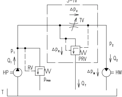
A schematic diagram of a hydraulic system including three-way throttle valve with pressure gradient stabilization is shown in figure 1. The three-way throttle
valve 3-TV is located in front of the rotary hydraulic motor HM. It consists of the throttle valve TV and the pressure reducing valve PRV. These valves are connected in parallel [2]. The constant flow hydraulic pump HP with the liquid flow Q1 is a source of pressure energy. The relief valve RV is used to system protection against overload. A size of the flow Q2 to the hydraulic motor is controlled by the throttle valve. It remains practically constant independently of load changes. The excessive flow QT through the pressure reducing valve is given by
the difference between the input flow Q1 and the output flow Q2.
Figure 1. Schematic diagram of hydraulic system with three-way throttle valve and pressure gradient stabilization.
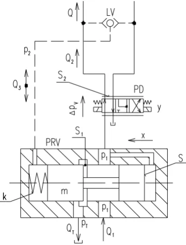
The working principle of the three-way throttle valve with pressure gradient stabilization (type SP 12L30/TD 250 RM01) is shown in figure 2. The throttle valve is C
Owned by the authors, published by EDP Sciences, 2015
replaced by the proportional distributor PD in this case [3]. An actual pressure signal p2 from a motor load is fed through the logical valve LV into one side of the slide valve of the pressure reducing valve PRV. The input pressure p1 is fed into the other side of the slide valve. The hydraulic resistance of the pressure reducing valve is decreasing with decreasing the motor load. For this reason the valve permeability is increasing. Similarly, the hydraulic resistance of the valve is increasing with increasing the motor load and the valve permeability is decreasing in this case. The pressure gradient through the proportional distributor is practically constant (i.e. Δpv= 1 ÷ 2 MPa) during control of the pressure reducing
valve. The cross section of the investigated pressure reducing valve [4] is shown in Figure 3.
Figure 2. Schematic diagram of working principle of three-way throttle valve with pressure gradient stabilization.
Figure 3. Cross section of pressure reduction valve.
The equilibrium of forces with respect to the moving slide valve of the valve PRV in the x direction (see figure 2) is expressed by the equation:
݉ ήௗమ௫
ௗ௧మ ܾ ήௗ௫ௗ௧ ݇ ή ݔ ൌ ሺଵെ ଶሻ ή ܵ, (2)
where m is mass of the slide valve (m = 0.21 kg), b is damping coefficient of the slide valve (commonly b = 100 N⋅s⋅m-1), k is spring rate (k = 15 329 N⋅m-1) and S is cross-sectional area of the slide valve (S = 2.54⋅10-4 m2) [3].
The flow Q into a hydraulic motor depends on a load change of the motor and is given by the formula:
ܳ ൌ ܳଶേ ܳଷ, (3)
where Q2 is linearized flow through the proportional distributor and Q3 is flow above the slide valve of the pressure reducing valve. These flows are expressed by the following formulas [3]:
ܳଶൌ ܵ௩ή ݕ ܼ௩ή ሺଵെ ଶሻ, (4)
ܳଷൌ ܵ ήௗ௫
ௗ௧, (5)
where Sv is sensitivity of the proportional distributor
(Sv = 0.011 m2⋅s-1), y is displacement of the slide valve of
the distributor and Zv is leakage permeability of the
distributor (Zv = 1.2⋅10-11 N-1⋅m5⋅s-1).
The linearized flow QT through the pressure reducing
valve having the throttle cross-section S1 (see figure 2) into the tank is described by the equation [3]:
்ܳ ൌ ்ܵή ݔ ்ܼή ଵ, (6)
where ST is sensitivity of the pressure reducing valve
(ST = 6.22 m2⋅s-1), and ZT is leakage permeability of the
pressure reducing valve (ZT = 6.4⋅10-10 N-1⋅m5⋅s-1).
The values of the above-mentioned quantities were experimentally determined [3] in terms of geometry of the three-way throttle valve with pressure gradient stabilization and the oil density ρ = 828 kg⋅m-3.
3 Dynamical behaviour of three-way
throttle valve with pressure gradient
stabilization
The dynamical behaviour of the investigated three-way throttle valve with pressure gradient stabilization during movement of the slide valve (see figure 2 and figure 3) to the left (i.e. due to decrease of motor load or by reason of decrease of the throttle cross-section S2 of the proportional distributor) is described by the following equations [4]:
݉ ήௗమ௫
ௗ௧మ ܾ ή
ௗ௫
ௗ௧ ݇ ή ሺݔ ݔሻ ൌ ሺଵെ ଶሻ ή ܵ, (7)
ܳଵൌ ்ܵή ݔ ்ܼή ଵ ܳ ൌ ܿ݊ݏݐǤ, (8)
ܳ ൌ ܵ௩ή ݕ ܼ௩ή ሺଵെ ଶሻ ܵ ήௗ௫
ௗ௧, (9)
where x0 is initial spring compression (x0 = 23.2 mm) and Q1 is input flow from the hydraulic pump.
proportional distributor), the dynamical behaviour of the three-way throttle valve is expressed by the equations [4]:
݉ ήௗమ௫
ௗ௧మ ܾ ή
ௗ௫
ௗ௧ ݇ ή ݔ ൌ ሺଶെ ଵሻ ή ܵ ݇ ή ݔ, (10)
ܳଵൌ െ்ܵή ݔ ்ܼή ଵ ܳ ൌ ܿ݊ݏݐǤ, (11)
ܳ ൌ ܵ௩ή ݕ ܼ௩ή ሺଵെ ଶሻ െ ܵ ήௗ௫
ௗ௧. (12)
3.1. Simulation of dynamical behaviour for throttling of proportional distributor
Dynamical properties of the three-way throttle valve with pressure gradient stabilization were investigated using Mathcad software and by the Laplace transformation. There are considered only dynamical (i.e. non-constant) quantities in mathematical simulations [3].
3.1.1 Simulation of dynamical behaviour using Mathcad software
Mathematical simulation of dynamical behaviour of the three-way throttle valve with pressure gradient stabilization was firstly performed for the throttling (i.e. Δy = −1.5 mm) of the slide valve of the proportional distributor. There were supposed constant values of the input flow Q1 and the pressure p2 in these simulations. For this reason the Eqs. (7) ÷ (9) are modified as follows:
݉ ήௗమ௫
ௗ௧మ ܾ ή
ௗ௫
ௗ௧ ݇ ή ݔ ൌ ଵή ܵ, (13)
Ͳ ൌ ்ܵή ݔ ܵ௩ή ݕ ሺܼ௩ ்ܼሻ ή ଵ ܵ ήௗ௫
ௗ௧. (14)
On the basis of a mathematical treatment of the above-mentioned equations, it is possible to express the differential equation of the position change of the slide valve of the pressure reducing valve depending on the throttling of the proportional distributor:
ௗమ௫
ௗ௧మ ൌ െ
ଵ ή ቀܾ
ௌమ
ೡାቁ ή
ௗ௫ ௗ௧െ
െଵ ή ቀ݇
ௌήௌ
ೡାቁ ή ݔ െ
ௌೡήௌή௬
ήሺೡାሻ. (15)
The Eq. (15) was solved by the Runge-Kutta 4th order method using Mathcad software [5]. As a result of these simulations, the time dependencies of the position x and the velocity v = dx/dt of the slide valve of the pressure reducing valve are shown in figure 4 and figure 5. The slide valve of the pressure reducing valve is in a new steady-state position after the time t≅ 0.01 s (see figure 4 and figure 5) in consequence of the transient change.
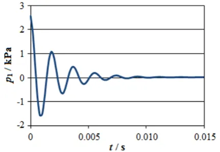
The time dependence of the input pressure p1 (see figure 6) is determined from the Eq. (14):
ଵൌ െೡାଵ ή ቀ்ܵή ݔ ܵ௩ή ݕ ܵ ήௗ௫ௗ௧ቁ. (16)
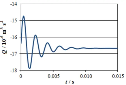
Similarly, the output flow Q (see figure 7) can be expressed from the Eq. (9):
ܳ ൌ ܵ௩ή ݕ ܼ௩ή ଵ ܵ ήௗ௫
ௗ௧. (17)
It is obvious that throttling of the proportional distributor gives rise to a reduction of the input flow (see figure 7).
Figure 4. Time dependence of position of slide valve of pressure reduction valve.
Figure 5. Time dependence of velocity of slide valve of pressure reduction valve.
Figure 7. Time dependence of output flow.
It is evident (see figure 4 ÷ figure 7), that the simulated time dependencies are damped periodic with the period of oscillation T ≅ 0.0018 s (see Figure 4), which is proportional to the eigenfrequency f0:
݂ൌଵ
்؆ ͷͷͷǤ. (18)
3.1.2 Determination of eigenfrequency by Laplace transformation
It is possible to obtain more accurate values of the period of oscillation and the eigenfrequency by the Laplace transformation. The Laplace image F(s) of the time function f(t) is defined by the formula [6, 7]:
ܨሺݏሻ ൌ ܮሼ݂ሺݐሻሽ ൌ ݁ஶ ି௦ή௧ή ݂ሺݐሻ݀ݐ
, (19)
where s is parameter of the Laplace transformation. The transfer function Fyx(s) of a system is equal to its
transpose [8]:
ܨ௬௫ሺݏሻ ൌሼ௬ሺ௧ሻሽ
ሼ௫ሺ௧ሻሽൌ ሺ௦ሻ ሺ௦ሻൌ
ሺ௦ሻ
ீሺ௦ሻ, (20)
where Y(s) is Laplace image of an output quantity y, X(s) is Laplace image of an input quantity x, g(s) is numerator of the transfer function and G(s) is denominator of the transfer function. If the denominator G(s) = 0, it is possible to determine the transfer function poles sk:
ݏൌ ߙേ ݅ ή ߱, (21)
where αk is real part of transfer function poles, i is
imaginary unit and ωk is imaginary part of transfer
function poles. The system eigenfrequency f0 can be subsequently determined from the equation:
݂ൌఠೖ
ଶήగ. (22)
After Laplace transforming, the Eqs. (13) and (14) are modified as follows:
݉ ή ݏଶή ܺሺݏሻ ܾ ή ݏ ή ܺሺݏሻ ݇ ή ܺሺݏሻ ൌ ܲ
ଵሺݏሻ ή ܵ, (23) Ͳ ൌ ்ܵή ܺሺݏሻ ܵ௩ή ܻሺݏሻ
ሺܼ௩ ்ܼሻ ή ܲଵሺݏሻ ܵ ή ݏ ή ܺሺݏሻ. (24)
In this case, the transfer function FP1Y is given by the
ratio of the Laplace image P1(s)of the input pressure and the Laplace image Y(s)of the slide valve position of the proportional distributor. It is possible to determine the transfer function FP1Y from the Eqs. (23) and (24):
ܨభሺݏሻ ൌభሺ௦ሻ
ሺ௦ሻ ൌ
ିௌೡή൫ή௦మାή௦ା൯
ௌమή௦ାௌήௌାሺೡାሻήሺή௦మାή௦ାሻ (25)
If the denominator value of the Eq. (25) is equal to zero, then the obtained transfer function poles sk = −475.724 ± 3382i. For this reason the eigenfrequency
of the investigated three-way throttle valve with pressure gradient stabilization is determined as follows:
݂ൌଷଷ଼ଶ
ଶήగ ൌ ͷ͵ͺǤʹ. (26)
3.2. Simulation of dynamical behaviour for step increase in load
3.2.1 Simulation of dynamical behaviour using Mathcad software
Mathematical simulation of dynamical behaviour of the investigated three-way throttle valve was also performed for the step increase of the output pressure (i.e. Δp2 = 5 MPa). There are supposed constant values of the input flow Q1 and the position y of the slide valve of the proportional distributor. Then the Eqs. (10) ÷ (12), describing the dynamical behaviour of the step increase in load, are modified in the following manner:
݉ ήௗௗ௧మ௫మ ܾ ή
ௗ௫
ௗ௧ ݇ ή ݔ ൌ ሺଶെ ଵሻ ή ܵ, (27) Ͳ ൌ െ்ܵή ݔ ்ܼή ଵ ܼ௩ή ሺଵെ ଶሻ െ ܵ ήௗ௫ௗ௧. (28)
The differential equation of the position change of the slide valve of the pressure reducing valve depending on the output pressure is obtained from the Eqs. (27) and (28) as follows:
݀ଶݔ ݀ݐଶൌ െ
ͳ ݉ή ቆܾ
ܵଶ ܼ௩ ்ܼቇ ή
݀ݔ ݀ݐെ
െଵ ή ቀ݇ ௌήௌ
ೡାቁ ή ݔ
మήௌή
ήሺೡାሻ. (29)
Figure 8. Time dependence of position of slide valve of pressure reduction valve.
Figure 9. Time dependence of velocity of slide valve of pressure reduction valve.
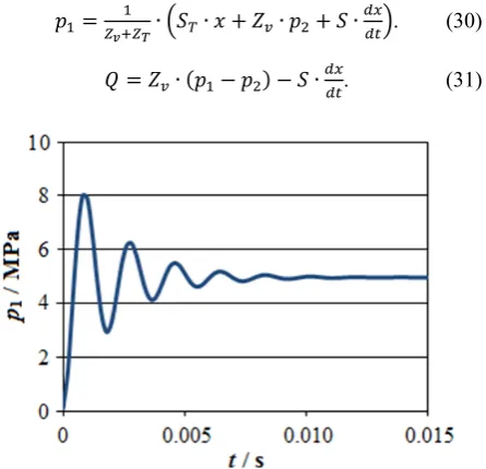
The time dependencies of the input pressure p1 (see figure 10) and the output flow Q (see figure 11) are derived from the Eqs. (28) and (12):
ଵൌೡାଵ ή ቀ்ܵή ݔ ܼ௩ή ଶ ܵ ήௗ௫ௗ௧ቁ. (30)
ܳ ൌ ܼ௩ή ሺଵെ ଶሻ െ ܵ ήௗ௫
ௗ௧. (31)
Figure 10. Time dependence of input pressure.
Figure 11. Time dependence of output flow.
It is obvious (see figure 10), that the input pressure increment Δp1 is practically same as the step change of the output pressure (i.e. Δp1 ≅ Δp2 = 5 MPa). For this reason the pressure gradient through the proportional distributor is practically independent of a motor load:
ο௩ൌ ଵെ ଶ؆ . (32)
Then the flow Q is also independent (see figure 11) of the motor load (see Eq. (1)). It is a big advantage of three-way throttle valves with pressure gradient stabilization compared to ordinary throttle valves.
It is again evident (see figure 8 ÷ figure 11), that the time dependencies of the simulated quantities are damped periodic with the eigenfrequency f0 ≅ 555.6 Hz.
3.2.2 Determination of eigenfrequency by Laplace transformation
After Laplace transforming, the Eqs. (27) and (28) are modified as follows:
݉ ή ݏଶή ܺሺݏሻ ܾ ή ݏ ή ܺሺݏሻ ݇ ή ܺሺݏሻ ൌ ൌ ൫ܲଶሺݏሻ െ ܲଵሺݏሻ൯ ή ܵ, (33)
Ͳ ൌ െ்ܵή ܺሺݏሻ െ ܼ௩ή ܲଶሺݏሻ
ሺܼ௩ ்ܼሻ ή ܲଵሺݏሻ െ ܵ ή ݏ ή ܺሺݏሻ. (34)
The transfer function FXP2 is expressed by the ratio of
the Laplace image X(s) of the slide position and the Laplace image P2(s) of the output pressure. It is determined from the Eqs. (33) and (34):
ܨమሺݏሻ ൌ ሺ௦ሻ
మሺ௦ሻൌ
ήௌ
ௌమή௦ାௌήௌାሺೡାሻήሺή௦మାή௦ାሻ. (35)
4 Conclusions
The purpose of the paper was to investigate dynamical behaviour and eigenfrequency of three-way throttle valve with pressure gradient stabilization. It was performed for two different transient changes, specifically for step change in position of the slide valve of the proportional distributor and for step change of a motor load.
The eigenfrequency was determined by two different methods, i.e. using Mathcad software and by Laplace transformation. It was found by the two methods that the eigenfrequency of the three-way throttle valve with pressure gradient stabilization is very high (i.e. f0 = 538.26 Hz) in this case. These methods are advantageous mainly from time and financial point of view compared to experimental measurements. They also allow to simulate different working states of hydraulic systems. For the above-mentioned reasons these methods are frequently applied at the present time.
Throttle valves (including the three-way throttle valve with pressure gradient stabilization) have important functions in hydraulic systems too. They have an additional damping effect during transient changes of systems. They are used to elimination of oscillations in hydraulic systems. For this reason it is suitable to locate the throttle elements closest to hydraulic consumers because hydraulic motor in conjunction with hydraulic line create a mechanical oscillating system. It was also verified that liquid flow through the three-way throttle valve with pressure gradient stabilization is independent on load changes of a hydraulic motor. For this reason the speed (or the velocity) of the hydraulic motor is practically constant and independent on the motor load. It is a big advantage of these valves compared to ordinary throttle valves. Furthermore the efficiency of hydraulic systems with three-way throttle valves is higher compared to hydraulic systems that are controlled by ordinary throttle valves.
References
1. H. Exner, R. Freitag, H. Geis, R. Lang, J. Oppolzer, P. Schwab, E. Sumpf, R.A. Lang, The Hydraulic Trainer Volume 1 – Basic Principles and Components of Fluid Technology (Mannesmann Rexroth GmbH, Lohr am Main, 1991)
2. H. Dörr, R. Ewald, J. Hutter, D. Kretz, F. Liedhegener, A. Scmidt, The Hydraulic Trainer Volume 2 – Proportional and Servo Valve Technology (Mannesmann Rexroth GmbH, Lohr am Main, 1986)
3. M. Vašina, Energy saving hydraulic systems of lifting and loading equipment mounted on lorries (VŠB – Technical University of Ostrava, Czech Republic, 2000)
4. Mannesmann Rexroth GmbH, (catalog sheets) 5. P. Dudek, Mathcad – User´s Guide (Grada, Prague,
1992)
6. P. P. Valkó, L. Abate, Computers & Mathematics with Applications 48, 3-4 (2004)
7. F. Durbin, Computer Journal 17, 4 (1974)
8. J. Rommes, N. Martins, IEEE Transactions on Power Systems 21, 3 (2006)
Acknowledgements
This paper has been elaborated in the framework of the project Opportunity for young researchers, reg. no. CZ.1.07/2.3.00/30.0016, supported by Operational Programme Education for Competitiveness and co-financed by the European Social Fund and the state budget of the Czech Republic.