Design and Analysis of 32 channel
WDM-MIMO Free Space Optics link under Different
Atmospheric Conditions
Jaspreet Kaur1, Monika Aggarwal2
M. Tech Student, Department of ECE, BGIET Sangrur, Punjab, India1
PG SAssociate Professor, Department of ECE, BGIET Sangrur, Punjab, India2
ABSTRACT: Free space optics (FSO) is a favourable technique to access the optical communication services. This technology used for transmitting data from one point to another point by using a laser beam. There are many projects to analyse the performance of free space optics system in different atmospheric conditions. But they are not applicable more than 2 km range on higher attenuation.
In the paper, the main objective is to increase the link range of the transmission channel and the capacity of the system by increasing the 32 channels of wavelength division multiplex (WDM). The losses considered are geometric losses, transmitter losses, receiver losses and most important atmospheric conditions (having different attenuation value for a different condition). The proposed design consists of forks & a power combiner and multi-input and multi-output technique (MIMO) which take benefits from the spatial diversity. For high-quality communication, multiple channels are used to achieve the goal. Theoretically, the analysis reveals that multiple inputs and multiple outputs (MIMO) improve the capacity, throughput, and reliability of the optical communication system. To prove it practically, the performance of the optical system is analyzed by the received power, Q-factor and bit error rate (BER) under different link range and atmospheric conditions.
KEYWORDS: Free space optics, MIMO, Wavelength division multiplexing, Geometric loss, Atmospheric
attenuation, OptiSystem 7.0, BER and Q-Factor
I. INTRODUCTION
Free Space Optics is a communication Technology in which data is transmitted by propagation of light in free space or air. FSO is a line of sight technology for successful transmission of optical signal. The FSO based communication System used in hours in lesser economy. The basic characteristics of FSO are that it operates at a higher power level for long distance communication; high-speed modulation required for high-speed FSO based communication system. The FSO has various applications like it’s used in outdoor wireless access, storage area network, last mile access, enterprise connectivity, fiber backup, Metro-network extension, backhaul, service acceleration, bridge WAN access, military Access, point to point or multi-point, ship to ship etc [1].
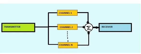
Systems with multiple transmitter and receiver antennas are called as Multiple Input and Multiple Output (MIMO) System. This wireless technique has significantly improved the capacity and range of wireless communication channel. A MIMO system provides multipath propagation by using different transmission path to the receiver, which provides redundancy of data thus increases the reliability of transmission. By this technique transmitting the amount of data transmitted is also increased. MIMO system has also offered high-speed reliable data range at the same power and bandwidth [2]. So, MIMO is a beneficial technique for FSO system.
Fig. 1 MIMO systems
II. ATMOSPHERIC EFFECT ON FSO
FSO provides the best way to communicate for the geographical area where the optical fiber is not feasible but there are some performance limitations like atmospheric losses and geometrical losses.
The atmosphere is the transmission medium of optical communication System. The atmosphere has various conditions which attenuate the signal. These atmospheric conditions are fog, rain, Haze (smoke, dust and other dry particles.)
Geometrical loss: - In FSO communication system, the geometrical losses directly affect the optical power and laser
beam which spread the light from one point to another point of the link [3]. Geometrical effect can be calculated by received power
=
( + ) 10
Where = received aperture diameter (m) = transmitter aperture diameter (m) = beam divergence (mrad)
R = link range (km)
= atmospheric attenuation (dB/km)
Beer’s law describes the atmospheric attenuation( ) [4]
( )R
Where, and are absorption and scattering coefficients R is a Link Range
Rain attenuation: -The highest attenuation factor in the environment is rain attenuation for light so it also effects FSO. The rain can reduce the visibility of FSO system. Due to Rain intensity factor, the FSO System and laser power are affected. The attenuation due to rain is:-
= 1.076 .
Where,
R represents the rainfall rate.
Fog attenuation: -Fog is the most unfavourable attenuation factor among all atmospheric attenuations. Fog has scattered the incident light because it’s a visible mass of water droplets which has reduced visibility. The attenuation is calculated from Kruse model by:
= 17
550
Where V is the visibility in km and q is the particle size distribution.
Low visibilities increases atmospheric attenuation and reduce the availability of optical signals from free space [5].
Haze attenuation: -Haze is an atmospheric condition where dust, smoke, and other dry particles reduce the clarity of the sky. The particles are staying longer in the atmosphere as compared to rain. This attenuation has more serious degradation of FSO performance. Kim and Kruse's model is used to calculate specific attenuation as
= 3.91
550
Where V is visibility in km and q is particle size distribution. The q values are obtained from Kim and Kruse model [5]
III. SYSTEM DESIGN AND ANALYSIS
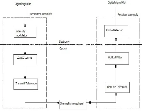
The fundamental elements of FSO communication system are Transmitter, transmission channel, and receiver. To analyse the performance of the optical communication system the simulator software namely Optisystem version 7 is used. The block diagram of the optical communication system is shown in fig. 2
Fig. 2 The block diagram of the optical communication system
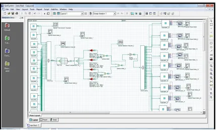
In the simulation design, the transmitter section consists of 32 channels. Each channel has CW laser, Mach-Zehnder modulator, Pseudo-random bit sequence generator (PRBS), NRZ pulse generator and an optical amplifier. The CW laser is used as a carrier signal with 7.7 dBm input power. PRBS generate the binary input. With the help of Mach-Zehnder, the binary input is converted into a light signal or optical signal.
These signals are multiplexed by WDM MUX carrying 32 wavelengths. The input laser has the wavelength range from 1525.2 nm to 1550 nm with 100 GHz (0.8 nm) channel spacing. The bandwidth of the WDM is 10 GHz. WDM system is used in FSO optical System to maximize the bandwidth usage but in low cost.
Table 1 Specification of the simulation design
PARAMETER VALUE
Data rate 2.5 Gb/s
Wavelength 1550 nm
Laser Power 7.7 dBm
No. of inputs 32
Bandwidth 10 GHz
Channel spacing 0.8 nm (100 GHz)
Transmitter aperture diameter
10 cm
Receiver aperture diameter
30 cm
Range 500 m to 4500 m
EDFA 5 m
No. FSO channels 4
The output of the MUX is connected to the fork. The fork is used for duplicating the input beam. The power combiner is used to combine the outputs or multiple laser beam of a fork. The output coming from power combiner is send to the FSO transmission channel. The FSO system is called the two telescope subsystem with intermediate FSO channel. The optical adder sums the two optical signals. The adder adds up the amplitude of the two input signals. EDFA amplifier is used to improve the signal quality and increase the range of communication.
In the receiver section, a WDM DEMUX is used with same specifications of the multiplexer. DEMUX divide the signal according to wavelength. Then a photodetector, a low pass filter, 3R regenerator and a visualizer is used at every port of DEMUX. The visualizer gives the value of maximum Q factor, minimum BER, eye height, threshold value. The simulation design of optical communication system is shown in fig. 3
IV. RESULT AND CONCLUSION
All the experiments done on FSO channel shows that heavy rain (19.2km/dB) is the most severe factor in tropical regions, that reduce the availability of the link. There is no problem of fog and snow in tropical regions. In this section, numerical results for the FSO Communication System are presented with different attenuation values and distance. In FSO Communication System transmit and receiving aperture of lens system is10 cm and 30 cm respectively.
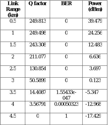
The attenuation value of 19.2dB/km for heavy rain is considered. The table 2 shows the Q-factor, BER and received the power of the system.
Table 2 Performance at different link range
Link Range
(km)
Q factor BER Power
(dBm)
0.5 249.813 0 39.479
1 249.498 0 24.256
1.5 243.308 0 12.483
2 211.077 0 6.636
2.5 130.854 0 3.697
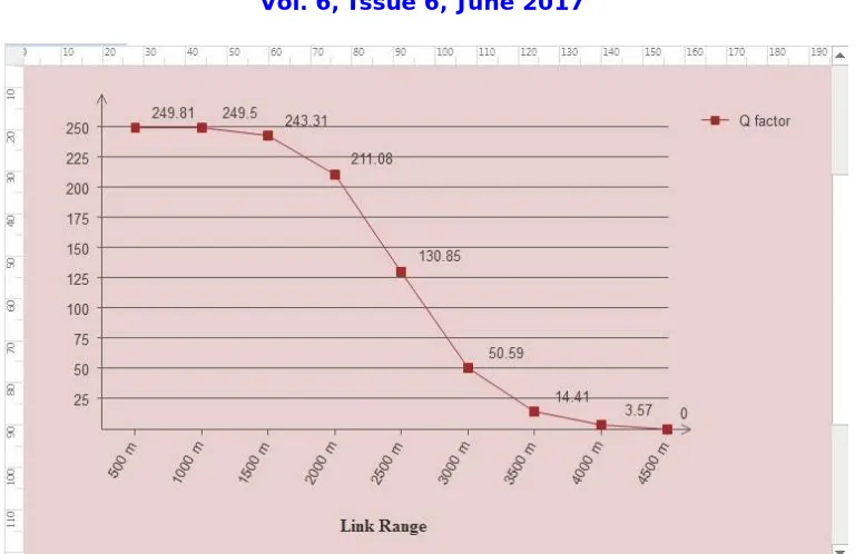
3 50.5899 0 0.123
3.5 14.4087 1.55433e-047
-5.347
4 3.56791 0.00050323 -12.968
4.5 0 1 -17.429
Fig. 4 The Q factor Vs Link Range
Table 3 shows the performance of the FSO optical communication system according to atmospheric attenuation at the link range 3.5 km.
Table 3 Q factor, BER, Power of system at link range 3.5 km
Atmospheric condition
Attenuation value (dB/km)
Q factor
BER Power
(dBm)
Very clear 0.065 249.763 0 32.525
Clear 0.233 249.756 0 31.938
Light haze 0.55 249.740 0 30.832
Heavy haze 2.37 249.517 0 24.517
Light rain 6.27 242.850 0 12.206
Medium rain 9.64 210.497 0 6.600
Low fog 15.55 61.1459 0 0.812
Heavy rain 19.2 14.4087 1.55433e-047
-5.347
Heavy fog 43 0 1
Fig. 5 Power Vs Link range
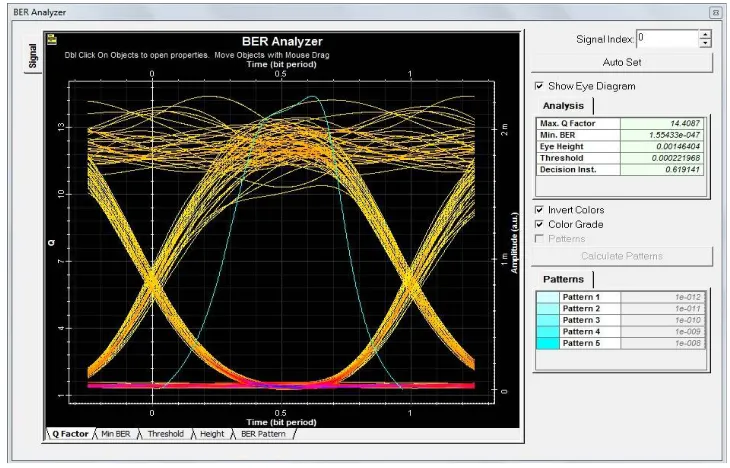
The eye diagram of the FSO communication system under heavy rain attenuation is shown in fig. 6 For heavy rain optimized link range is 3.5 km with 19.2 dB/km attenuation of heavy rain.
Free Space Optics is the promising communication technology. Due to atmospheric losses and geometrical losses the signal gets distorted at receiver. To overcome this problem the new MIMO technology is implemented which has reduced the atmospheric effect on signal and increase the capacity of the system. The information can transmit in the range 3.5 km. By using MIMO technology, the reliability of the system is also improved.
It is realized that MIMO FSO system can operate successfully for a link distance of 3500 m at BER of 1.55433e-047 with a received optical power of -5.347dBm and link distance of 4000 m at BER of 0.000150323 with a received optical power of -12.968dBm for heavy rain.
REFERENCES
[1] Aditi Malik and Preeti Singh, “Free Space Optics: Current Applications and Future Challenges”, Hindawi Publishing Corporation International Journal of Optics Volume 2015, Article ID 945483
[2] Ruchi Modi, Vineeta Dubey and Deepak Garg “Spatial Diversity Techniques in MIMO with Free Space Optical Communication”, ICRISTME-19 May 2016
[3] Nishu Sahu and Jayesh C. Prajapati “Optimization of WDM-FSO link using Multiple Beams under different rain conditions,”International Journal of Advanced Research in Electronics and Communication Engineering (IJARECE), 5 May 2015
[4] Salasiah Hitam, Siti Norziela Suhaimi, Ahmad Shukri Mohd Noor, Siti Barirah Ahmad Anas and Ratna Kalos Zakiah Sahbudin “Performance Analysis on 16-Channels Wavelength Division Multiplexing in Free-Space Optical Transmission under Tropical Regions Environment”, Journal of Computer Science 8 (1): 145-148, 2012
[5] Rekha Reghunadh, Lakshmy G.B “Efficiency Comparison of Diversity Techniques in FSO links for Fading Mitigation using EDFA and APD”,International Journal of Innovative Research in Computer and Communication Engineering,Vol. 5, Issue 3, March 2017
[6] Dr. Rasa Bruzgiene,”Resilience of Optical Wireless Telecommunication System On The Weather-Based Disruptions”
[7] Dr. Shehab A. Kadhim, Dr. Alaa H. Ali, and Kanat M. Abdul Hussain ”Simulation and Comparative Analysis of (SISO over MIMO) FSO Communication Channel”,International Journal of Innovative Research in Science, Engineering and Technology, pp. 2347-6710, April 2017
[8] Abu Bakar Mohammad,“Optimization of FSO System in Tropical Weather using Multiple Beams,” IEEE 5th International Conference on Photonics (ICP), Kuala Lumpur, 2-4 Sept 2014.
[9] S. Robinson and K. Malaisamy,“Investigation on Free Space Optical Communication for Various Atmospheric Conditions”, Second International Conference on Electronics and Communication Systems (ICECS), pp. 1030-1034, 2015.
[10] Dhaval Shah and Dilip Kumar Kothari, “Optimization of 2.5 Gbps WDM-FSO link range under different rain conditions in Ahmedabad”, Annual IEEE India Conference (INDICON), 2014.
[11] Shaina and Amit Gupta “Mitigating the effects of Attenuation in Free Space Optics link using EDFA” International Journal of Scientific Engineering and Applied Science (IJSEAS), November 2015
[12] M. Matsumoto, “Next Generation Free-space Optical System by System Design Optimization and Performance Enhancement”, Proceedings of Progress in Electromagnetic Research Symposium, Kuala Lumpur, pp. 501-506, 2012
[13] Jyoti Saxena, Neel Kamal, and NitinThathai, “WDM-based FSO System for Long Haul Communication”, International Journal of Engineering Research and Technology (IJERT), Vol. 4, pp. 794-798, 2015.
[14] Aditi and Preeti, “An Effort to Design a Power Efficient, Long Reach WDM-FSO System,” International Conference on Signal Propagation and Computer Technology (ICSPCT), 2014.
[15] Sushank Chaudhary, Preety Bansal and Manisha Lumb,“Effect of Beam Divergence on WDM-FSO Transmission System”, International Journal of Computer Applications (0975 – 8887), Volume 93 – No 1, May 2014.
[16] J. Singh and N. Kumar, “Performance Analysis of Different Modulation Format on Free Space Optical Communication System”, Optik, vol. 124, no. 20, pp. 4651-4654, 2013
[17] Farhana Hossain “Impact of Travelling Wave Semiconductor Optical Amplifier on WDM-FSO System under Fog Attenuation” International Journal of Science and Research (IJSR) (2319-7064) Volume 3 Issue 4, April 2014
[18] Shikha Rani, Manoj Arora and Vishal Chaudhary, “MIMO Channel Capacity of Free Space Optical Communication System of OOK AND M-PPM”, International Journal of Advances in Science Engineering and Technology, ISSN: 2321-9009 Volume- 1, Issue- 1, July-2013 [19] M. A. Khalighi and M. Uysal, “Survey on Free Space Optical Communication: A Communication Theory Perspective”, IEEE
Communications Surveys & Tutorials, vol.14, no. 4, pp. 2231-2258, 2014.