OFDM in Free Space Optical Communication
System
Subhalekshmi K R, Sreelekshmi K R, Jacob Thomas
M. Tech Student, Department of ECE, Believers Church Caarmel Engineering College, Kerala, India
M. Tech Student, Department of ECE, Believers Church Caarmel Engineering College, Kerala, India Assistant Professor, Department of ECE, Believers Church Caarmel Engineering College, Kerala, India
ABSTRACT: The hybrid technology that combines the OFDM and FSO is helps to improve the overall performance of the communication system. FSO is the free space optical communication system where that transmit the data in the form of optical signals. The maximum BER of a FSO system will improved by using OFDM in it. The orthogonal frequency division technique used either BPSK or QAM modulation techniques. The comparative analysis of the system performance by using these two modulation schemes in OFDM which included in the FSO were carried out in this paper. The spectral efficiency provided by these two modulation schemes are different. FSO is a wireless communication technique which can be used for both short distance and long distance communication. The hybrid technology that combine both OFDM and FSO is complex but highly efficient. The comparative analysis of bit error rate versus signal to noise ratio is carried out. These shows that the OFDM using QAM in FSO provide better performance than that of PSK.
KEYWORDS:orthogonal frequency division multiplexing bit-error-rate;free space optical communication; spectral efficiency; binary phase shift keying; quadrature amplitude modulation.
I. INTRODUCTION
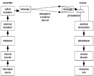
The information generated by a source is encoded by an encoder, interleaved, and modulated into an electrical waveform by an electrical modulator. In the optical modulator, the intensity of a light source is modulated by the output signal of the electrical modulator. The light source is a laser, characterized by its wavelength, power, and beam divergence angle. There is a collimator or telescope in the transmitter to determine the direction and the size of the laser beam. The receiver consists of an optical front end, a photodetector, a demodulator, a deinterleaver, and a decoder. The optical front end contains lenses focusing the received optical field onto a photodetector. The photodetector converts the received optical field to an electronic signal, which is demodulated. The demodulator output signal is deinterleaved and decoded. The decoded bits are fed into an information sink.
II.
R
ELATED WORKIn [1] used to describe about the major requirements and challenges of laser beam. Which describe the effective way to use the laser beam as a light source for the transmission purpose. [2]The indoor link ranges over short range and the outdoor connectivity range is greater than the indoor link. The outdoor link is established with LOS connectivity that is affected greatly by the atmospheric condition. The fade margin of the FSO system compels the designer to increase the transmitter power. But it is very essential to select the transmitter power within the eye safety requirement. When fade margin is quite high, the link is unavailable and the transmission is interrupted. Meteorological effects like fog, rain, mist, scintillation etc. causes the light to fade. Besides the meteorological effects, the atmospheric phenomena like absorption and scattering attenuates the optical signal in free space. The occurrence of these phenomena depends on the geographical area which in turn limits the availability of the FSO link
.
[3] By calculating the bit error rate is an effective way to understanding the system performance.III. MODULATIONSCHEMES
The optical carrier can be modulated in its frequency, amplitude, phase, and polarization. The most commonly used schemes because of their relatively simple implementation are amplitude modulation with direct detection and phase modulation in combination with a homodyne or heterodyne receiver. The technically simplest digital modulation scheme is amplitude-shift keying (ASK). In optical systems it is referred to as on-off keying (OOK). OOK is an intensity modulation scheme where the light source (carrier) is turned on to transmit a logic ”one” and turned off to transmit a ”zero”. In its simplest form this modulation scheme is called NRZ (non-return-to-zero)-OOK. Besides NRZ also other codes exist. The most common one besides NRZ is RZ (return to- zero) coding. The advantages of RZ compared to NRZ are its higher sensitivity and the fact that the clock frequency lies within the modulation spectrum. Unfortunately, both NRZ and RZ can lead to loss of clock synchronization if long strings of ones or zeros are transmitted. This can be avoided with other coding systems such as Manchester coding, which is related to RZ but amounts to state changes at the beginning or in the middle of clock cycles - pulse position modulation. With such a variant of RZ the clock of the digital signal can easily be recovered.
Fig. 2. Block diagram of an optical communication system through atmospheric turbulence channels.
Generally, an OOK system is more robust with regard to atmospheric distortion than a coherent modulation system. This is because for OOK the information is only encoded in intensity whereas PSK uses intensity and phase coding. Both the intensity and the phase of a beam are disturbed in atmospheric propagation. Further, OOK has mainly been used in optical fibre communications due to its low complexity. Additionally, many reliable and cost effective components are available in the market, which is important for the development of FSO communication terminals. As a result, OOK systems have been preferred for optical links inside the atmosphere. The advantages of FSO result from the basic characteristics of a laser beam, especially from its high frequency, coherency and low divergence, which lead to efficient delivery of power to a receiver and a high information carrying capacity. The basic characteristics of a laser beam provide the following additional advantages of FSO links:
A narrow beam guarantees high spatial selectivity so there is no interference with other links. The high available bit rate allows them to be applied in all types of networks.
The optical band lies outside the area of telecommunication regulation; therefore no license is needed for operation.
The small size and small weight of optical terminals enables links to be easily integrated into mobile systems.
IV. OFDMINFREESPACEOPTICALCOMMUNICATION
varies from symbol to symbol. Thus link availability of OFDM based FSO system depends not only on the atmospheric condition, but also on the signal power of the symbol. The FSO can be classified based on the ambient condition as- indoor link and outdoor link.OFDM being a parallel transmission system widely applied in the wireless environment that is affected by the multipath propagation effects. FSO being a wireless application, combining OFDM with FSO can provide new hybrid technology that can take the advantage of both OFDM and the FSO systems. The data rate of transmission can be increased by the OFDM modulation of the signal that can easily be transmitted through FSO link over window panes or terrace to form ubiquitous connectivity. While combining the two techniques, compatible system parameters have to be chosen. It use BPSK baseband modulation and the weak turbulent atmospheric condition was modelled by lognormal distribution. The power level of the OFDM signal varies from symbol to symbol, so the link margin under varying power level is calculated for different climatic condition.
V. FSO–OFDMSYSTEM
The hybrid technique FSO-OFDM consists of generating OFDM in the baseband domain which is used to modulate the optical source. Thus the electrical signal is converted into light that is subjected to varying climatic conditions. The complex OFDM signal is given as:
Where T is the symbol duration, ak is the data bits, and w (.) is the rectangular window function. The above equation represents each symbolak is amplitude modulated on orthogonal subcarriers. This process is performed using the IFFT which guarantees that all the subcarriers are orthogonal to each other over the symbol interval. Here, we set the guard interval to zero and thus the OFDM symbol duration T equals to the Fourier analysis window. The OFDM signal with N subcarriers modulates the intensity of laser diode and it is considered to be linear. The optical power from the diode is represented as:
Where Pt is the average transmitted optical power, mn is the Optical Modulation Index (OMI) for each subcarrier and the total OMI is given as:
V. BASIC CONFIGURATION OF OFDM SIGNAL TRANSMISSION OVER FSO LINK
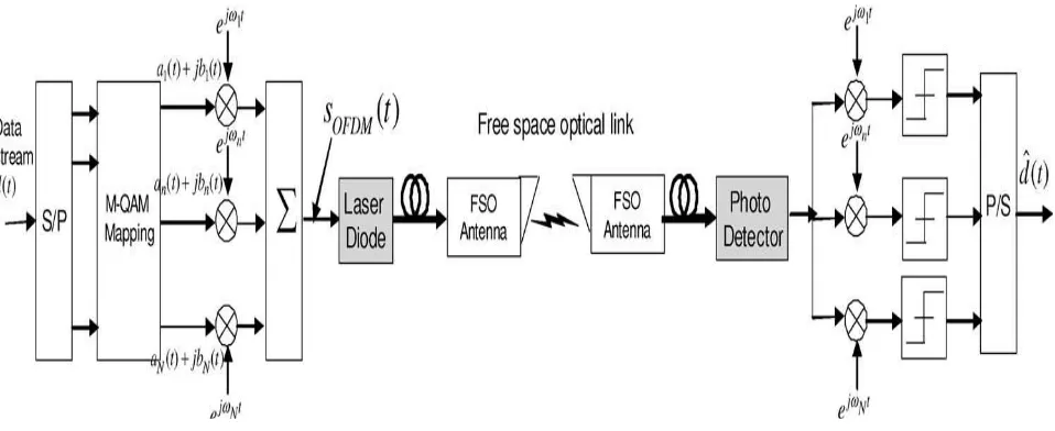
OFDM is a kind of multicarrier transmission in which high data rate streams are split into lower rate streams and then transmitted simultaneously over several narrow-band subcarriers. The subcarriers are themselves modulated by using phase shift keying (PSK) or quadrature amplitude modulation (QAM) and are then carried on a high frequency carrier. OFDM can be simply defined as a form of multicarrier modulation where its carrier spacing is carefully selected so that each subcarrier is orthogonal to the other subcarriers and can be separated at the receiver by correlation techniques; hence, inter symbol interference among channels can be eliminated. The set of orthogonal carriers is realized by using the inverse fast Fourier transform (IFFT) at the transmitter and the fast Fourier transform (FFT) at the receiver.OFDM-FSO system support high data rates by splitting a high-rate stream into a number of low-rate data-streams and transmitting these over a number of narrowband subcarriers. The narrowband subcarrier data-data-streams experience smaller distortions than high-speed ones and require no equalization. Moreover, most of the required signal processing is performed in the free space domain. This is advantageous because microwave devices are much more mature than their optical counterparts and because the frequency selectivity of microwave filters and the frequency stability of microwave oscillators are significantly better than that of corresponding optical devices.
Fig. 3. Basic configuration of OFDM signal transmission over FSO link
VI. SIMULATION RESULTS
The simulation result shows that the OFDM-FSO system with QAM modulation have more spectral efficiency than that of the PSK modulation technique since it have more constellation points. Also the particular SNR value the BER will be less in QAM than that of PSK. Results shows that the OFDM-FSO system with QAM is more efficient than that of PSK. But the OFDM-FSO system with PSK provide better performance than that of regular FSO system. The combination of the OFDM in FSO will helps to improve performance of the FSO communication system. Fig. 4 and fig. 5 gives the comparative study of PSK and QAM modulation technique. Fig. 6 and fig. 7 gives the efficiency of the system in both PSK and QAM. From fig. 4 and fig. 5, the QAM system performs well than that of PSK in FSO-OFDM system. Also the fig. 6 and fig. 7 reviles the idea that efficiency will be better in QAM system than that of PSK modulation technique.
VII. CONCLUSIONS
provide improved performance than that of simple FSO system. The OFDM modulated signal will be transmitted through the free space in the form of optical signal by using optical modulation of the signal. The emerging technology that provide both OFDM and FSO is a high scope technology in wireless communication.
VIII. ACKNOWLEDGMENT The authors would like to thank Prof. Saju A for discussing the concept.
REFERENCES
1. Das, S., Henniger, H., Epple, B., Moore, C., Rabinovich,W., Sova, R., Young, D. Requirements and challenges for tacticalfree-space lasercomm. In IEEE Military Communications Conference San Diego (USA), 2008, p. 1 – 10.
2. Hennes HENNIGER, Otakar WILFERT Institute of Communications and Navigation, German Aerospace Center (DLR), 82230 Wessling, Germany2University of Technology Purkynova 118, CZ-61200 Brno, Czech Republic an Introduction to Free-space Optical Communicationsradio engineering, vol. 19, no. 2, June 2010.
3. Pauer, M., winter, P., Leeb, W. Bit error probability reductionin direct detection optical receivers using rz coding. Journal of Light wave Technology, 2001, vol. 19, no. 9, p. 1255 – 1262.
4. Jia Li, Member, IEEE, John Q. Liu, Senior Member, IEEE, and Desmond P. Taylor, Life Fellow, IEEEOptical Communication Using Subcarrier PSKIntensity Modulation through Atmospheric Turbulence ChannelsIEEE Transactions on Communications, Vol. 55, No. 8, August 2007 Phase Locked Loops” IEEE Trans. Power Electronics, 2013.
5. P. F. Szajowski, G. Nykolak, J. J. Auborn, H. M. Presby, G. E. Tourgee, and D. Romain, “Key elements of high-speed WDM terrestrial free space optical communications systems,” Proc. SPIE, vol. 3932, pp. 2–14,2000.
6. Zhu and J. M. Kahn, “Free-space optical communication through atmospheric turbulence channels,” IEEE Trans. Commun.,vol. 50, no. 8, pp. 1293–1300.Aug. 2002.
7. 1m. Selvi, 2k. Murugesan 1associate Professor, Department of ECE, Saveetha Engineering College, Thandalam, Chennai2professor and Head, Dept. of ECESree Sastha Institute Of Engineering & Technology, Chembarambakkam, Chennai Study Of Link Availability And Data Rate Analysis In Fso-Ofdm System International Journal Of Electrical, Electronics And Data Communication, Issn: 2320-2084 Volume-2, Issue-4, April-2014.D.
8. Nitin Shankar Singh Dept. of Electronics and Communication Lovely Professional University Phagwara, India Gurpartap Singh Assistant Professor Lovely Professional University Phagwara, India Performance Analysis of OFDM-FSO System using BPSK, QPSK and 8-PSK Modulation TechniquesInternational Journal of Computer Applications (0975 – 8887) Volume 66– No.17, March 2013.
9. Ales Prokes Dept. of Radio Electronics, Brno University of Technology, Purkyňova 118, 612 00 Brno, Czech Republic Modeling of Atmospheric Turbulence Effecton Terrestrial FSO LinkA. Prokes, Modeling Of Atmospheric Turbulence Effect On Terrestrial Fso Link. 10. M. A. Khalighi, N. Schwartz, N. Aitamers, and S. Bourennane, "Fading reduction by aperture averaging and spatial diversity in optical wireless
systems," Journal of Optical Communications and Networking, IEEE/OSA vol. 1, pp. 580-593, 2009.
BIOGRAPHY
Ms. Subhalekshmi K. R., received her B. Tech Degree in Electronics & Communication Engineering from Cochin University in 2013. At present she is pursuing M. Tech in Communication Engineering at Believers Church Caarmel Engg. College, Kerala.
Ms. Sreelekshmi K. R., received her B. Tech Degree in Electronics & Communication Engineering from Cochin University in 2013. At present she is pursuing M. Tech in Communication Engineering at Believers Church Caarmel Engg. College, Kerala.