ISSN(Online): 2320-9801
ISSN (Print): 2320-9798
International Journal of Innovative Research in Computer
and Communication Engineering
(An ISO 3297: 2007 Certified Organization)
Vol. 3, Issue 8, August 2015
Circularly Polarized Microstrip Patch
Antenna for WiMAX Applications
B.Madhuri, Dr. A. Jhansi Rani,
M.Tech, V.R.Siddhartha Engineering College, Vijayawada, Andhra Pradesh, India
Professor, Dept. of ECE., V.R. Siddhartha Engineering College, Vijayawada, Andhra Pradesh, India
ABSTRACT: Wireless communications need not only compact antennas but also which can radiate efficiently in more
than one band. Now-a-days antennas which are been operating at dual frequency are preferred. Generally Microstrip patch antennas which produce circular polarization can be used for this application. Circularly polarized (CP) antennas can resolve the conflicts caused by the transmitter-to-receiver coordination. The main idea is to enhance the bandwidth of operation within a single-feed square patch truncated at its corner. The design involves four slits inserted into a square patch and a T-shape slot is inserted which produces circular polarization between 2.5 GHz and 9 GHz WiMAX applications range. This structure offers size reduction compared to other conventional CP antenna designs. The parameters which are observed are return loss, VSWR, Radiation patterns at two different frequencies from 2.5GHz and 9 GHz.
KEYWORDS: Circularly polarization (CP),Worldwide Interoperability for microwave access (WiMAX)
I. INTRODUCTION
The advancement in the wireless communications is more evolved in recent years compared to the past. The necessity is more for compact antennas and which is been operated more than one band. Here, an antenna with a low profile, minor size, and a light weight is required in wireless communications [1]. A patch antenna is a narrow band, fabricated by engraving the antenna element pattern in metal trace to the insulating dielectric substrates such as PCB, with a constant metal layer merged to the opposite side of the substrate which forms a ground plane. Common microstrip patch antenna shapes are elliptical, square, and rectangular and any continuous shape is possible so far [2]. Some use and instant made of patch mounted above a plane and some do not use dielectric substrate. Moreover; this design is appropriate for great importance to design CP microstrip antenna structures with a single feed appliance to keep the configuration compact [3]. In the previous, various single and dual band CP patch antennas are been designed. These predictable designs of single feed square microstrip antennas for circular polarization (CP) are usually achieved by truncating patch corner [4].
Using a square patch and a T-slot we can achieve dual band [11]. By further adjusting the slits lengths these can be achieved by symmetrically truncating technique and feeding the patch using a single feed along the design [5]. Now circular polarization is used, it is the divergence of the electromagnetic wave in which either the electric or the magnetic vector effects a circle perpendicular to the path of the transmission with a frequency equal to that of a wave.
ISSN(Online): 2320-9801
ISSN (Print): 2320-9798
International Journal of Innovative Research in Computer
and Communication Engineering
(An ISO 3297: 2007 Certified Organization)
Vol. 3, Issue 8, August 2015
II.ANTENNADESIGN
Fig: 1. Design structure of circularly polarized antenna
The Figure 1 indicates that CP at the lower frequency is enabled by the centre asymmetrical T-slot and two diagonally-located, truncated corner [8]. On the other hand, two vertical slits located at the bottom right and top left corners of the patch radiator, further the truncated corner is an imperative element in allowing CP in the upper band[15]. Besides its structural simplicity, ease of fabrication and low cost, this antenna features a satisfactory impedance band-width in the lower band 2 GHz and upper band 9 GHz[9] .This antenna uses a simple microstrip feed to excite the microstrip patch to enable dual band resonance on a single layered structure.
This design is implemented by using the HFSS (High frequency structure simulator). It provides a good CP bandwidth. It can be observed from the simulations that creating asymmetrical corner facilitates the lowering of the axial ratio. Moreover, the corner is also utilized to reverse the negative effect of the parasitic slots on the axial ratio, where their angle optimization enabled the highest possible CP bandwidth for this structure [13]
.
The simulated antenna is considered in both lower band and higher band. The CP orientation can be changed by varying the truncated corner at the bottom [10]. To enable CP at frequencies, asymmetrical slots and the truncated corner is introduced onto the radiation. Unlike previous designs, this structure uses a simple microstrip feed to excite the microstrip patch to enable dual band on a single layered structure.
To enable CP at both frequencies, asymmetrical slots and the truncated corners introduced onto the patch. On the other hand, two vertical slits located at the bottom right and top left corners of the patch, besides the truncated corner allows the CP in the upper band [7].
Table 1: Dimensions of slots and patch antenna
W
1L
1L
2L
3L
4L
5L
6L
725mm
1mm
13mm
10mm
3mm
5mm
8mm
8.7mm
W
1- length of the square patch
L
1- length of the feed
L
2-length of the probe
L
4- length of the slot beside T-shape slot
ISSN(Online): 2320-9801
ISSN (Print): 2320-9798
International Journal of Innovative Research in Computer
and Communication Engineering
(An ISO 3297: 2007 Certified Organization)
Vol. 3, Issue 8, August 2015
L
6-length of T-shape slot
L
7- length of slot above the probe-line feed
L
3, L
8, L
9, L
10- length of the slots
III.DESIGN ANALYSIS
Dielectric substrate(FR4 Substrate) =4.4
Substrate height (h)
1.6 mm
W = 17.47mmto 34.93 mm
= (1+12h\W)-1/2 4.9 mm
= 0.412h ][
0.7209mm
= 13.5mm
- 13.5515mm to 27.11 mm
Design parameters:
FR4 substrate (εr) = 4.4
Frequency (f0) = 2.5GHz & 9 GHz Height (h) = 1.6mm.
ISSN(Online): 2320-9801
ISSN (Print): 2320-9798
International Journal of Innovative Research in Computer
and Communication Engineering
(An ISO 3297: 2007 Certified Organization)
Vol. 3, Issue 8, August 2015
Design of microstrip patch antenna using HFSS:
Fig. 2: Design of patch antenna using HFSS Fig.3: Design of antenna using HFSS with radiation box
As shown in Fig.2 it is the geometrical design of the microstrip patch antenna by using various slots and truncated corner.A good CP bandwidth is also effectively enabled by the conventional technique of edge-chamfering at the resonator patch corner. Furthermore, the corner is utilized to reverse the negative effect of the parasitic slots where the angle optimization enables the highest possible CP bandwidth for the structure.
IV. SIMULATION RESULTS
The simulation results for microstrip patch antenna carried out at operating frequency 2.5GHz and 9GHz and the results return loss, VSWR, radiation patterns, 3D polar plot are observed. The simulation results of the antenna are observed by using the HFSS software. The simulation was carried out for return loss and VSWR from 1GHz and10 GHz.
ISSN(Online): 2320-9801
ISSN (Print): 2320-9798
International Journal of Innovative Research in Computer
and Communication Engineering
(An ISO 3297: 2007 Certified Organization)
Vol. 3, Issue 8, August 2015
Figure 4: Simulated Return loss of patch antenna carried out from 1GHz to 10GHz.
It is conveyed from Fig.4 the simulated Sparameters of CP antenna operating at 2.5GHz the return loss is about -20.46 dB and 9 GHz the return loss is about -28.50 dB .From the figure 4 it shows that the return loss is less than -10dB so that it operates at 2.5 GHz and 9 GHz.
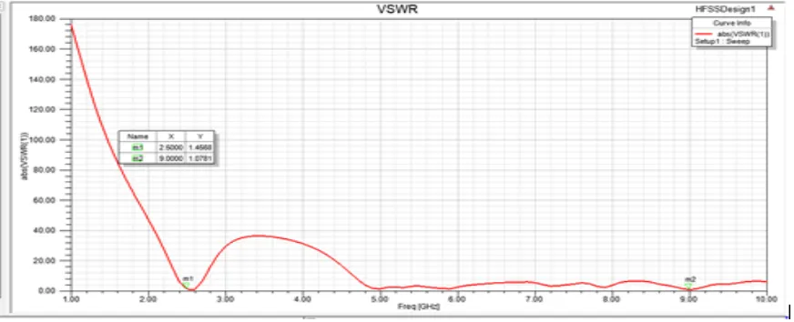
Figure 5: VSWR of CP antenna operating at 2.5GHz and 9 GHz
From the Fig.5 the simulated results of VSWR is carried out from 2GHz and 10GHz. But the operating frequency is at 2.5 GHz to 9GHz. It is clearly observed that the VSWR is <2 at both the operating frequencies
.
Table 2: Return loss and VSWR of the antenna
Frequency Return loss VSWR
2.5GHz -20.4622dB 1.45
9GHz -28.5033dB 1.07
ISSN(Online): 2320-9801
ISSN (Print): 2320-9798
International Journal of Innovative Research in Computer
and Communication Engineering
(An ISO 3297: 2007 Certified Organization)
Vol. 3, Issue 8, August 2015
Table 3: Comparison of antenna design for different substrate materials
Substrate
Materials FR 4 ROGER’S ARLON
Relative
permittivity 4.4 2.2 3.2
Bandwidth 2.5GHz,9GHz 2GHz,9 GHz 2.4GHz,8.7GHz
Gain 2.4052dB 5.0079dB -1.371dB
Return loss(dB) -20.46,-28.503 -17.0223,-13.58 -17.0323,-13.58
VSWR < 2 < 2 < 1.7
By observing the Table 3 , these results indicate a dual band CP operation with two different bands for three different materials. It shows that by using the FR4 substrate efficiency is more compared to other substrate materials. The relative permittivity for FR4 substrate is higher than the other two materials Roger’s and Arlon.
Fig.6: 3D Gain for Microstrip patch antenna at 2.5 GHz and 9 GHz
ISSN(Online): 2320-9801
ISSN (Print): 2320-9798
International Journal of Innovative Research in Computer
and Communication Engineering
(An ISO 3297: 2007 Certified Organization)
Vol. 3, Issue 8, August 2015
Fig.7: Radiation pattern for patch antenna at 2.5 GHz Fig.8: Radiation pattern for patch antenna at 9 GHz
From the Fig. 7 and 8 it is conveyed that the radiation pattern of patch antenna at 2.5 GHz and 9 GHz .On the other hand, the gain is slightly reduced in the upper band due to the expected FR4 losses at higher frequencies especially for a dual band, single patch antenna. The maximum gain at resonant frequency 2GHz is around 2dB and for 9 GHz is around 5 dB.
V. CONCLUSION
A dual band Microstrip patch antenna has been designed and analysed using HFSS software [ANSYSS]. Here one orthogonal mode is used for the production of circular polarization through the optimization of the slot. Moreover, the CP can be easily controlled through the T-shape slot and the truncated corner. Besides it is a simple and compact topology, the antenna is also low-cost and can be used for WiMAX applications.
This antenna is operated at two frequencies 2.5GHz and 9GHz and can be used for WiMAX applications. From the above results the variation of return loss of the Microstrip patch antenna is considered is below -10dB.The operating frequencies are at 2.5GHz the return loss is about -20.46 dB and 9 GHz the return loss is about -28.50 dB respectively. The VSWR at both the operating frequencies is < 2.
This work can be further extended by improving the bandwidth. Since cellular mobile is having a Wi-Fi option in the same way with this specific bandwidth a WiMAX option can be placed in that way we can increase number of users.
REFERENCES
[1] WONG, K. L., WU, J. Y. Single-feed small circularly polarized square microstrip antenna. Electronics Letters, 1997, Vol. 33, pp. 1833-1834. [2] CHEN, W. S., et al. Novel compact circularly polarized square microstrip antenna. IEEE Transactions on Antennas and Propagation, 2001, Vol. 49, pp. 340-342.
[3] Shing-Lung Steven Yang, Ahmed A.Kishk and Kai-Fong Lee et al. Wideband circularly polarized stacked microstrip antennas. IEEE Antennas and Wireless PropagationLetters, 2007, Vol. 6, pp. 21-24.
[4] Tuan –Yung Han, et al. Design of a broadband dual circularly polarized square slot antenna. Microwave and Optical Technology Letters, 2008, Vol. 50, pp. 2639-2642.
ISSN(Online): 2320-9801
ISSN (Print): 2320-9798
International Journal of Innovative Research in Computer
and Communication Engineering
(An ISO 3297: 2007 Certified Organization)
Vol. 3, Issue 8, August 2015
[6] TONG, K. F., WONG, T. P. Circularly polarized U-slot antenna. IEEE Transactions on Antennas and Propagation, 2007, Vol. 55, pp. 2382-2385.
[7] NASIMUDDIN, N., et al. Compact asymmetric-slit microstrip antennas for circular polarization. IEEE Transactions on Antennasand Propagation, 2011, Vol. 59, pp. 285-288.
[8] KUO, J. S., HSIEH, G. B. Gain enhancement of a circularly polarized equilateral-triangular microstrip antenna with a slotted ground plane. IEEE Transactions on Antennas and Propagation, 2011, Vol. 59, pp. 285-288.
[9] LAM, K. Y., et al. Small circularly polarized U-slot wideband patch antenna. IEEE Antennas and Wireless Propagation Letters, 2011, Vol. 10, pp. 87-90.
[10]K.F. Tong, K.M. Luk, K.F. Lee, and R.Q. Lee, “A broadband U-slot rectangular patch antenna on a microwave substrate,” IEEE Trans. Antennas Propag., Vol, 48, No.6, p.954, Jun .2000.
[11]Syed FizzahJilani et al, “Novel Star- shaped Fractal Design of Rectangular Patch Antenna for Improved Gain and Bandwidth” IEEE conference on Antennas Wireless Propag, 2013.
[12]Raj Kumar et al, “Novel Design of Star Shaped Circular Fractal Antenna,” Proceedings of IEEE international conference on microwave – 2008. [13]S. M. Noghabaei et al, “Dual-Band Circularly-Polarized Patch Antenna With A Novel Asymmetric Slot For WiMAX Application” Radio Engineering, Vol. 22, No. 1, April 2013.
[14]HFSS; “High frequency structure simulator based on the finite element method,” Vol. 9.2.1, and Soft Corporation, 2004.
[15] Prof. Mahesh M., “Design and Comparative Study of Different Feeding Mechanisms for Microstrip Antenna for Wireless Communication”, International Conference on Computational Intelligence & Computing Research (IEEEICCIC), , pp-638-641, December 15-18, 2011.
BIOGRAPHY
B.Madhuri pursuing Master of Technology in the stream of Communication Engineering and Signal Processing in VR
Siddhartha Engineering College. She has done the project work on designing a Circularly polarized microstrip patch antenna for WiMAX applications.
Dr. A.Jhansi Rani obtained her B.Tech Degree in Electronics and Communications Engineering from Velagapudi