ISSN (Print) : 2347 - 6710
I
nternational
J
ournal of
I
nnovative
R
esearch in
S
cience,
E
ngineering and
T
echnology
Volume 3, Special Issue 3, March 20142014
I
nternational
C
onference on
I
nnovations in
E
ngineering and
T
echnology (ICIET’14)
On 21st& 22nd March Organized by
K.L.N. College of Engineering, Madurai, Tamil Nadu, India
Copyright to IJIRSET www.ijirset.com 523 M.R. Thansekhar and N. Balaji (Eds.): ICIET’14
Optimal PMU Placement in Power System
Networks Using Integer Linear Programming
ABSTRACT—The Phasor Measurement Unit (PMU) is an important tool for monitoring and control of the power system. It gives real time, synchronized measurements of voltages at the buses and also current phase values which are incident to those buses where these PMUs are located. This paper presents a topological approach to determine the optimal PMU placement in order to make the system completely observable using binary integer linear programming. The proposed formulation istested on various IEEE test systems and results so obtained for complete observability of system at normal condition and with loss of single PMU are also presented in this paper. The proposed PMU placement has been implemented on IEEE -14, 30, 57 and 118 bus systems, practical 75-bus system of Utter-Pradesh State Electricity Board (UPSEB) and New England 39-bus system.
KEYWORDS: Phasor Measurement Unit, Optimal PMU Placement, Integer Linear Programming.
I. INTRODUCTION
PMU is a measuring device used to measure voltage and current phasors. PMUs use a global positioning system (GPS) pulse to provide synchronized measurements of real time phasors of voltage and currents [1]. A power system is said to be observable when voltage phasors at all the buses are known
viz. Obviously, when PMUs are installed at all the buses of network, and the measurements of all PMUs are communicated to control centers, then voltage phasors at all buses (and current phasors in all transmission lines) would be known. This technology can potentially change the traditional state estimation to state measurement [2]. However, as described later in this section, even when PMUs are not installed at all the buses, a power system may be observable if the voltage phasors at the buses without PMUs can be calculated using the network parameters and the PMU measurements at other buses.Such buses are said to have pseudo-measurements [3].
A number of PMUs are already installed in several utilities around the world for various applications such as adaptive protection, system protection schemes, and state estimation [1]. Other application areas include wide area
monitoring and control (WAMC), stability monitoring, and enhanced as well as efficient system utilization. PMUs are an integral part of smart grids, and hence the rate of PMU installations is increasing. One of the most important issues that need to be addressed in the emerging technology of PMUs is their placement, which is influenced by the intended system application. The important factor limiting the number of PMU installations is their cost and available communication facilities, the cost of which may be higher than that of the PMUs [1]. So the communication and cost constraints of PMUs have motivated power engineers and researchers to find minimal PMU placement for intended applications.
Several techniques and algorithms have been proposed for optimal PMU placement for power system observability during normal operating conditions [1], [3]-[6]. Optimal PMU placement for complete and incomplete observability has been proposed in [1] using spanning trees of a power system graph. An integer programming based method for optimal placement of PMUs is proposed in [4-5] for complete observability of a power system.
The proposed integer programming formulation has considered system cases with normal condition and with single PMU outage. A generalized integer linear programming (ILP) method for optimal PMU placement has been discussed in [6-9] which includes cases of full observability, incomplete observability and placement of a PMU for redundancy [10]. Duae.t al. [11] have discussed various aspects of the optimal PMU placement problem, and have proposed a procedure for multi-staging of PMU placement in a given time horizon using ILP. Multi-stage scheduling determines the locations of PMU placement in different stages of time horizon, and would be useful when utilities have cost constraint to place all the required PMUs in a single project. Thus, several methods and algorithms have been proposed for optimal PMU placement. However, they only ensure the observability during healthy operating conditions. Only a
Pradeep S. Chauhan, S. P. Singh
Department Of Electrical Engineering Department, IIT (BHU) Varanasi, India
Copyright to IJIRSET www.ijirset.com 524 M.R. Thansekhar and N. Balaji (Eds.): ICIET’14
few papers [12]-[13] have discussed optimal PMU placement to locate a fault in a power system.
If a set of measurements available is sufficient enough to locate the position of any fault within a system, then the system is said to be fault observable. An observable system under normal operating conditions may not be fault observable. This is because a fault in a transmission line changes the network configuration, and a faulted network has one more bus (fault-point) than the corresponding healthy network. In order to restore the system operation quickly after a fault, it is necessary to precisely locate and correct the fault in a transmission line as soon as possible. Different fault location algorithms have been proposed for locating faults in transmission lines. Different algorithms have different assumptions and require different sets of input data. In summary, it has been found that synchronized measurements at both ends of a transmission line result in the most accurate fault location. Therefore, ideally, placing PMUs at all the system buses makes the system fault observable with good accuracy of fault location. However, due to the cost constraints, optimal PMU placement is desired for the purpose of fault observability as well.
The paper is arranged in IV sections, section I covers the introduction part. Section II explains the basic principles forobservability of the system. Section III explains OPP problem formulation and section IV present the simulation results, comparison and implementation of the PMU in different practical systems. Lastlysections V, VI covers the conclusion and references respectively.
II. OBSERVABILITYRULES
Power system observability is important for finding out the real time monitoring and state estimation of the system. The network is said to be observable if sufficient measurements are observable, such that all the states of the system, as well as the current and voltage phasors at all the buses can be estimated. There are three classes of algorithms used for this purpose, namely, numerical, topological and hybrid techniques. For a network to be numerically observable, its gain or measurement Jacobian matrix should be of full rank [14]. A network is said to be topologically observable if it contains at least one spanning measurement tree of full rank [15]. Since numerical observability technique involves calculation of huge matrices, topological approach is more preferable. Thus, this approach has been used in the work. The topological observability techniques focus on finding a spanning tree of full rank with the placement of the PMUs for Wide Area Monitoring (WAM) purpose. While formulating the optimal PMU placement (OPP) problem, there are certain rules and assumptions which are to be followed [16].
i. For PMU installed buses, voltage phasor and current phasor of all its incident branches are known. These are called as direct measurements.
ii. If voltage and current phasors at one end of a branch are known then voltage phasor at the other end of the branch can be obtained. These are called pseudo measurements.
iii. If voltage phasors of both ends of a branch are known then the current phasor of this branch can be obtained directly. These measurements are also called pseudo measurements.
III.OPPPROBLEMFORMULATION
The OPP problem can be divided into different subsections as shown below:
The OPP problem formulation based topological observability method finds a minimal set of PMUs such that a bus must be reached at least once by the PMUs to make it observable. The optimal placement of PMUs for an N bus system is formulated as follows:
𝑀𝑖𝑛 𝑁𝑘=1𝑤𝑘𝑥𝑘 (1)
𝑆. 𝑇. 𝐶𝑃𝑀𝑈𝑍 ≥ 𝑏
𝑍 = [𝑧1𝑧2 … … … … . 𝑧𝑁]𝑇 (2)
𝑧 ∈ 0, 1
Where, N is total no. of system buses, wk is weight
factor accounting to the cost of installed PMU at bus k, for convenience purpose wk is taken to be equal to 1. Z is
a binary variable vector whose entries are defined as Eq. 3 and 𝐶𝑃𝑀𝑈𝑍 is a vector function such that its entries are non-zero if the corresponding bus voltage is observable using the given measurement set and according to observability rules mentioned above, it ensure full network observability while minimizing the total installation cost of the PMUs, otherwise its entries are zero.
𝑍𝑘= 1 , 𝑖𝑓 𝑎 𝑃𝑀𝑈 𝑖𝑠 𝑛𝑒𝑒𝑑𝑒𝑑 𝑎𝑡 𝑏𝑢𝑠 𝑘0 , 𝑜𝑡ℎ𝑒𝑟𝑤𝑖𝑠𝑒 (3)
The entries in 𝐶𝑃𝑀𝑈 are defined as follows:
𝑐𝑖,𝑗 =
1 , 𝑖𝑓 𝑖 = 𝑗 1 , 𝑖𝑓 𝑖 𝑎𝑛𝑑 𝑗 𝑎𝑟𝑒 𝑐𝑜𝑛𝑛𝑒𝑐𝑡𝑒𝑑 0 , 𝑜𝑡ℎ𝑒𝑟𝑤𝑖𝑠𝑒
(4)
Copyright to IJIRSET www.ijirset.com 525
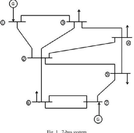
M.R. Thansekhar and N. Balaji (Eds.): ICIET’14 𝑏 = [1 1 … … … … .1]𝑇 (5) The procedure for building the constraint equations will be described for three possible cases where there are (1) no conventional measurement, (2) flow measurements or (3) flow measurements as well as injection measurements (they may be zero injections or measured injections). Case1: Presence of only PMU in network (No conventional measurement) In this case, the flow measurement and the zero injection are ignored. In order to form the constraint set, the binary connectivity matrix𝐶𝑃𝑀𝑈, whose entries are defined in Eq. (6), will be formed first: 𝑐𝑖,𝑗 = 1 , 𝑖𝑓 𝑖 = 𝑗 1 , 𝑖𝑓 𝑖 𝑎𝑛𝑑 𝑗 𝑎𝑟𝑒 𝑐𝑜𝑛𝑛𝑒𝑐𝑡𝑒𝑑 0 , 𝑜𝑡ℎ𝑒𝑟𝑤𝑖𝑠𝑒 Matrix 𝐶𝑃𝑀𝑈 can be directly obtained from the bus admittance matrix by transforming its entries into binary form. Consider a 7-bus system, as shown in Fig. 1, to illustrate the formulation processes of building matrix 𝐶𝑃𝑀𝑈 as given by Eq. (6). Fig. 1. 7-bus system Building the 𝐶𝑃𝑀𝑈 matrix for the 7-bus system of Fig. 1 yields: 𝐶𝑃𝑀𝑈 = 1 1 1 0 0 0 0 1 1 1 1 1 1 0 1 1 1 1 0 0 0 0 1 1 1 1 0 0 0 1 0 1 1 0 1 0 1 0 0 0 1 1 0 0 0 0 1 1 1 (6) The constraints for this case can be formed as: 𝑓 𝑍 = 𝑓1= 𝑧1+ 𝑧2+ 𝑧3 ≥ 1
𝑓2= 𝑧1+ 𝑧2+ 𝑧3+ 𝑧4+ 𝑧5+ 𝑧6 ≥ 1
𝑓3= 𝑧1+ 𝑧2+ 𝑧3+ 𝑧4 ≥ 1
𝑓4= 𝑧2+ 𝑧3+ 𝑧4+ 𝑧5 ≥ 1
𝑓5= 𝑧2+ 𝑧4+ 𝑧5+ 𝑧7 ≥ 1
𝑓6= 𝑧2+ 𝑧6+ 𝑧7 ≥ 1
𝑓7= 𝑧5+ 𝑧6+ 𝑧7 ≥ 1
The operator “+” serves as the logical “OR” and the use of 1 in the right hand side of the inequality ensures that at least one of the variables appearing in the sum will be non-zero. The constraint f1 ≥ 1 implies that at least one PMU must be placed at either one of buses 1, 2 or 3 (or at each buses) in order to make bus 1 observable. Similarly, the second constraint f2≥ 1 indicates that at least one PMU should be installed at any one of the buses 1, 2, 3, 4, 5, or 6 in order to make bus 2 observable. Or in other words for the complete observability of the system the rank of the connectivity matrix should be equal to the total no of buses present in the systemviz. Rank of matrix 𝐶𝑃𝑀𝑈 = Total no of buses present in the system Case 2: Loss of single PMU Till now, it is considered that each bus is observable by one PMU and these PMUs, placed by proposed algorithm, will function properly. PMUs highly reliable but, if because of any disturbance in power system or for maintenance purpose any of these optimally placed PMU is out from system than some of the buses connected through it may not remain observable. To guard against such unexpected failure of PMUs, a strategy is developed to account for single PMU loss. This objective is accomplished if all buses are observable by at least two PMUs. These PMUs will function in two sets, one will work as primary set and other set will work as backup set. So, if one PMU from primary set will not function than backup set will make the system observable. To get these sets of PMU, the objective and constraint function will remain same with the only change in matrix b. For this case the elements of matrix b will be equal to 2 instead of 1, as for previous case, as shown below: 𝑏 = 2 2. . 2 (7)
So, new constraints function can be formulated as: 𝑓 𝑍 = 𝑓1= 𝑧1+ 𝑧2+ 𝑧3 ≥ 2
𝑓2= 𝑧1+ 𝑧2+ 𝑧3+ 𝑧4+ 𝑧5+ 𝑧6 ≥ 2
𝑓3= 𝑧1+ 𝑧2+ 𝑧3+ 𝑧4 ≥ 2
𝑓4= 𝑧2+ 𝑧3+ 𝑧4+ 𝑧5 ≥ 2
𝑓5= 𝑧2+ 𝑧4+ 𝑧5+ 𝑧7 ≥ 2
𝑓6= 𝑧2+ 𝑧6+ 𝑧7 ≥ 2
Copyright to IJIRSET www.ijirset.com 526 M.R. Thansekhar and N. Balaji (Eds.): ICIET’14
IV.SMULATION RESULTS
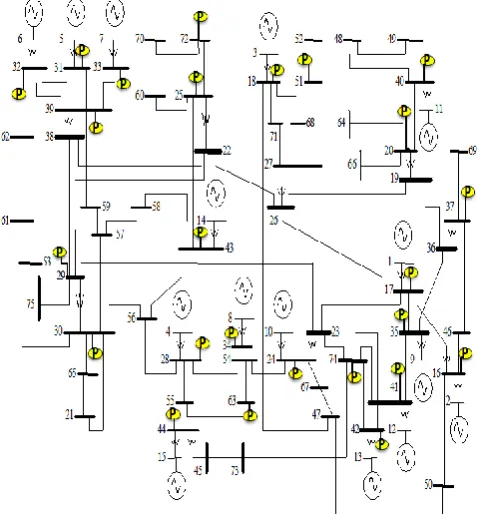
The proposed formulation is tested on various IEEE test systems and two practical systems namely New England-39 bus and UPSEB-75 bus system. The method explained in section III has been simulated by developing a MATLAB program and used to solve the PMU placement problem. And the results obtained for complete observability of system at normal condition and with loss of single PMU are shown in the table 1 and table 2 respectably which will be beneficial for real time monitoring, fault detection and voltage stability analysis. Figure 3 and figure 4 shows UPSEB -75 bus test system for complete observability of system at normal condition and with loss of single PMU respectably.
TABLE 1:OPP AT NORMAL CONDITION
Bus System
No. of PMU’s for Complete Observability
Location of PMU’s
IEEE-9 3 4,7,9
IEEE-14
4 2,6,7,9
IEEE-30
10 1,7,9,10,12,18,24,25,27,28
IEEE-39
13 12,16,19,20,22,23,25,29,30, 33,34,37,39
IEEE-57
17 1,4,6,13,20,22,25,27,29,32, 36,39,41,45,47,51,54 UPSEB
-75
25 16,17,18,20,24,25,28,29,30, 31,32,33,34,35,37,39,40,41, 42,43,44,51,63,72,74
IEEE-118
32 3,7,9,11,12,17,21,25,28,34, 37,41,45,49,53,56,62,63,68, 70,71,76,79,85,86,89,92,96, 100,105,110,114
Fig. 2. Optimal PMU locations for the New England39-bus system (at normal condition)
Fig. 3. Optimal PMU locations for the UPSEB -75bus system at normal condition
TABLE 2:OPP WITH LOSS OF SINGLE PMU
Bus System
No. of PMU’s for Complete Observability
Location of PMU’s
IEEE-9 6 1,2,3,4,7,9 IEEE-14 9 2,4,5,6,7,8,9,11,13 IEEE-30 21 1,3,5,7,8,9,10,11,12,13,1
5,17,19,20,22,24,25,26,2 8,29,30
IEEE-39 28 1,3,4,5,6,7,8,9,10,11,12,1 3,16,18,19,20,22,23,25,2 6,29,30,32,33,34,36,37,3 9
IEEE-57 33 1,3,4,6,9,12,15,19,20,22, 24,26,28,29,30,31,32,33, 35,36,38,39,41,43,45,46, 47,50,51,53,54,56,57
UPSEB-75
55 1,2,3,4,5,6,7,8,9,10,11,12 ,13,14,15,16,17,18,20,24, 25,27,28,29,30,31,32,33, 34,35,37,39,40,41,42,43, 44,47,49,51,52,55,57,60, 61,63,64,65,66,69,70,72, 73,74,75
Copyright to IJIRSET www.ijirset.com 527 M.R. Thansekhar and N. Balaji (Eds.): ICIET’14
Fig. 4. Optimal PMU locations for the UPSEB -75bus system (with loss of single PMU)
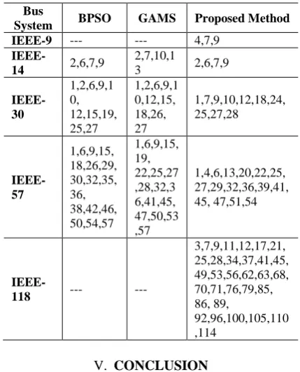
A comparative study is also done by comparing the results so obtained from the proposed method with Binary Particle Swarm Optimization (BPSO) and GAMS [17] for complete observability of the various test systems. In comparative analysis it is found that, though the locations obtained are not unique but the optimized value of objective function and numbers of PMUs obtained are same, as depicted by table 3 and table 4.
TABLE 3:NO. OF PMU’S BY DIFFERENT METHODS
Bus System BPSO GAMS Proposed Method (BLIP)
IEEE-9 --- --- 3
IEEE-14 4 4 4
IEEE-30 10 10 10
New England-39
--- --- 13
IEEE-57 17 17 17
UPSEB-75 --- --- 25
IEEE-118 --- --- 32
TABLE 4:PMU’S LOCATION USING DIFFERENT METHODS
Bus
System BPSO GAMS Proposed Method IEEE-9 --- --- 4,7,9
IEEE-14 2,6,7,9
2,7,10,1
3 2,6,7,9
IEEE-30
1,2,6,9,1 0, 12,15,19, 25,27
1,2,6,9,1 0,12,15, 18,26, 27
1,7,9,10,12,18,24, 25,27,28
IEEE-57
1,6,9,15, 18,26,29, 30,32,35, 36, 38,42,46, 50,54,57
1,6,9,15, 19, 22,25,27 ,28,32,3 6,41,45, 47,50,53 ,57
1,4,6,13,20,22,25, 27,29,32,36,39,41, 45, 47,51,54
IEEE-118 --- ---
3,7,9,11,12,17,21, 25,28,34,37,41,45, 49,53,56,62,63,68, 70,71,76,79,85, 86, 89,
92,96,100,105,110 ,114
V. CONCLUSION
This method proposes a simple algorithm of optimal placement of PMU’s in power system for full observability of network. The OPP problem is formulated using topology based algorithm and solved using binary integer linear programming. Besides the placement of PMU’s at normal condition, this study also considers the PMU placements when there is single PMU outage. The present case also accomplished the two objectives, first to develop practical methods for determining optimal locations for PMU’s and second is to develop the methods for implementation and to obtain test results. Simulation result on different IEEEtest systems, 39- New England and UPSEB 75-bus system indicate that the proposed placement method satisfactorily provides observable system measurements with minimum number of PMU’s.
REFERENCES
[1] R. F. Nuqui, A. G. Phadke, and L. Fellow, “Phasor Measurement Unit Placement Techniques for Complete and Incomplete Observability,” vol. 20, no. 4, pp. 2381–2388, 2005.
[2] A. Abur and A.G. Exposito, "Power System State Estimation", New York: CRC Press, 2004.
[3] R. Sodhi and S.C. Srivastava,” Optimal PMU Placement To Ensure Observability Of Power System,”, presented at Fifteenth National Power Systems Conference, IIT Bombay, Dec. 16-18, 2008.
[4] B. Xu, and A. Abur, “Observability Analysis And Measurement Placement For Systems With PMU's,” in Proc. 2004 IEEE Power Eng. Soc. Conf. Expo., vol. 2, pp. 943-946,Oct 10-13, 2004.
[5] F. Aminifar, M. Fotuhi-firuzabad, and M. Shahidehpour, “Probabilistic Multistage PMU Placement in Electric Power Systems,”IEEE Trans. on Power Del., vol. 26, no. 2, pp. 841–849, April 2011.
Copyright to IJIRSET www.ijirset.com 528 M.R. Thansekhar and N. Balaji (Eds.): ICIET’14
[7] S.E. Razavi, H. Falaghi, and M. Ramezani, “A New Integer Linear Programming Approach for Multi-Stage PMU Placement,”
2013 Smart Grid Conf., pp. 119–124, Dec. 2013.
[8] B. Gou, “Generalized Integer Linear Programming Formulation for Optimal PMU Placement,” IEEE Trans.Power Sys., vol.23, no. 3, pp.1099-1104, Aug. 2008.
[9] S. Chakrabarti, E. Kyriakides, and D. G. Eliades," Placement of Synchronized Measurements for Power System Observability "
IEEE Trans On Power Del., Vol. 24, no. 1, pp. 12-19, Jan 2009. [10] M. Esmaili, K. Gharani, and H. A. Shayanfar, "Redundant
Observability PMU Placement in the Presence of Flow Measurements Considering Contingencies" IEEE Trans. On Power Sys,.vol. 28, no. 4, pp. 3765-3773 Nov 2013.
[11] D. Dua, S. Damphare, R. K. Gajbhiye, and S.A. Soman, “Optimal Multistage Scheduling Of PMU Placement: An ILP Approach,”
IEEE Trans. on Power Del., vol. 23, no. 4, Oct. 2008.
[12] K. P. Lien, C. -W. Liu, C. –S. Yu, and J.-A. Jiang, “Transmission Network Fault Location Observability With Minimal PMU Placement,” IEEE Trans. on Power Del., vol.21, no. 3, pp.1128-1136, Jul. 2006.
[13] K. Mazlumi, H. A. Askarian, S. H. Sadegi, and S. S. Geramian, “ Determination Of Optimal PMU Placement for Fault-Location Observability,” in Third international conference on Electric Utility Deregulation and Restructuring and Power Technologies, pp. 1938-1942April 6-9, 2008,.
[14] T. L. Baldwin, L. Mili, M. B. Boisen, Jr., and R. Adapa, "Power System Observability With Minimal Phasor Measurement Placement", IEEE Trans. on Power Sys., vol. 8, no. 2, pp. 707-715, May 1993.
[15] F. Aminifar, C. Lucas, A. Khodaei and M. Fotuhi-Firuzabad "Optimal Placement of Phasor Measurement Units Using Immunity Genetic Algorithm," IEEE Trans. on Power Del., vol. 24, no. 3, pp. 1014-1020, Jul 2009.
[16] B. Xu and A. Abur, "Observability analysis and measurement placement for system with PMUs," in Proc. IEEE Power Sys. Conf. Expo, vol. 2, pp. 943-946, Oct. 2004.
[17] C. Sharma and B. Tyagi, “An Approach for Optimal PMU Placement Using Binary Particle Swarm Optimization With Conventional Measurements,” Int. Jour. of Eng. Sci. and Tech.,