Pandian Saraswathi Yadav Engineering College, Arasanoor, Sivagangai, Tamilnadu, India
ETC System Design for Image Using Random
Permutation and Run Length Encoding
Veena M
1, Sankar S
2P.G. Student, Department of Computer Engineering, KCG College of Technology, TamilNadu, India1
Associate Professor, Department of Computer Engineering, KCG College of Technology, TamilNadu, India2
ABSTRACT:In many practical scenarios, image encryption has to be conducted prior to image compression. This has
led to the problem of how to design a pair of image encryption and compression algorithms such that compressing the encrypted images can still be efficiently performed. In previous paper, compression has been performed by arithmetic coding, efficiency still unsatisfactory. In proposed method, encryption is operated in prediction error domain using random permutation to achieve high level of security and compression is operated via run length encoding and modified flood fill algorithm. This algorithm is newly proposed here, which is adopted to find connected pixel in 8 directions as well as in circular directions. It is used to predict similar characteristics of pixels and can be able to grouped together as single region, so achieve better compression efficiency. The Experimental results are demonstrated to compare with the state-of-the art method in terms of compression efficiency.
KEYWORDS: Encryption, Compression, Random Permutation, Run Length Encoding, Modified Flood fill algorithm.
I. INTRODUCTION
With the rapid development of multimedia and network technologies, the security of multimedia becomes more and more important, since multimedia data are transmitted over open networks more and more frequently. Typically, reliable security is necessary to content protection of digital images. Encryption can be defined as the art of converting data into coded form which can be decode by intended receiver only who poses knowledge about the decryption of the ciphered data. Encryption can be applied to text, image, and video for data protection. According to [13] image compression is an application of data compression that encodes the original image with few bits. The objective of image compression is to reduce the redundancy of the image and to store or transmit data in an efficient form.
[7]. Wei Liu et al., showed that encrypted images can be compressed progressively in terms of resolution. The decoder observes statistics of resolution, by using that information can be improved quality. In paper [11] concentrated on the lossless compression of image using approximate matching technique and run length encoding. The performance of this method is compared with the available jpeg compression technique over a wide number of images, showing good agreements. The present work focuses on improving compression efficiency by applying same run length encoding technique.
II. EXISTING SYSTEM
In [1], Encryption is achieved via random permutation and compression technique is adaptive arithmetic coding. In terms of compression efficiency is slightly worse than the state-of-the-art lossless/lossy image coders, which take original, unencrypted images as input. First encryption consists of five stages. GAP is applied to whole image according to CALIC [8], then estimated values are mapped in the range [0-255] explained in [7]. The algorithmic procedure of performing the image encryption is in [1].At firstall the mapped prediction errors e'i, jof the whole image
I should be calculated. The prediction errors divide into Lclusters Ck, for 0 ≤ k ≤ L − 1, and each Ckis formed by
concatenating the mapped prediction errors in a raster-scan order. Prediction errors in each Ckreshaping into a 2-D
block having four columns and |Ck|/4 rows, where |Ck| denotes the number of prediction errors in Ck.Performing two
key-driven cyclical shift operations to each resulting prediction error block, and read out the data in raster -scan order to obtain the permuted cluster Ck.
Let CSkand RSkbe the column secret key vector, Row Secret key in Ck. Here, CSkand RSk are obtained from the key
stream generated by a stream cipher, using different keys for same sessions. The assembler concatenates all the permuted clusters C'k, for 0 ≤ k≤ L−1, and generates the final encrypted Image. An Adaptive Arithmetic Coding is
then employed to losslessly encode each prediction error sequence C'kinto a binary bit stream Bk. The compression of
the encrypted file Ie needs to be performed in the encrypted domain, network provider does not have access to the
secret key K. The joint decompression and decryption is performed to get reconstructed image I′.
III.PROPOSED SYSTEM
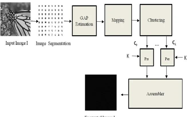
In this ETC system encryption is conducted prior to compression shown in figure 1. Here organized as encryption, compression, sequential decompression and decryption.
1) Encryption
This Encryption phase consists of six distinct stages. First input image (size 256×256) is divided into 32×32 block, called image segmentation. Each block is treated separately, applying GAP algorithm to each and every pixel in blocks. GAP-Gradient-Adjusted Prediction is estimated, this tries to detect how rapidly the edge is changing around pixel and then by classifying the tendency of edge changing into sharp, normal, and weak edge.Depends upon the CALIC [8], I'i,j is
estimated. Prediction error values ei,j are calculated as follows.
ei, j = Ii, j – I'i, j (1)
For 8-bit images, the prediction error ei, jcan potentially take any values in the range [−255, 255], it can be mapped into
the range [0, 255].The mean is calculated on known pixels;already know that the difference assumes value in the range [mean, 255mean]. If 255meanis greater than 127, the interval [128, 255mean] can be mapped in the interval [127, -mean-1]. More specifically, if Ii, j ≤ 128, we rearrange the possible prediction errors according to [7] each of which is
Pandian Saraswathi Yadav Engineering College, Arasanoor, Sivagangai, Tamilnadu, India
Fig. 1. ETC system block diagram
The Scanning algorithm ZZRD is a 2-D square matrix is split into exactly two halves diagonally, and the upper left part is scanned in Zigzag fashion, and the lower right part is in RasterDiagonal fashion slightly better than traditional Zigzag, which is proved in [9]. The proposed permutation algorithm is performed over the clusters from C0 to CL-1.
Random key is genetated according to the size of the cluster. Finally permutation process is performed with key generation and encryption algorithm. Specifically, permutation-based image encryption approach conducted over the prediction error domain. Depends on [10] encryption is achieved using two cyclical shift operations in the clusters. Here pixel values are shuffled randomly using constant key values, resulted in modified locations not values of pixels. Permuted clusters called C'k.Finally encrypted image is called Ie. Number of prediction errors equals that of the pixels,
the file size before and after the encryption remains same. Due to the high sensitivity of prediction error sequence against disturbances, reasonably high level of security could be retained. Further compression, decryption and decompression carried out over the encrypted image results. Performance results are demonstrated to compare efficiency.
(a) (b)
Fig. 3. Encrypted Results (a) Original image (b) Encrypted image
2) Compression
The encrypted Image (Ie) is again segmented into 32×32 sub blocks. Modified flood fill algorithm and Run Length
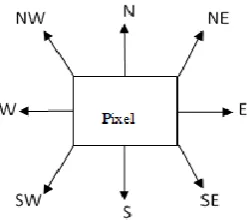
Encoding (RLE) technique is adopted for image compression RLE is one of the lossless image compression technique, which requires linear input. But in our image having 2D block, so modified flood fill algorithm is used to find same pixels as well as similar characteristics of pixels [12]. Specifically, circular directions are also considered here. Eight
directions namely N (North), NE (Northeast), E (East), SE (Southeast), S (South), SW (Southwest), W (West), NW (Northwest). Each direction should represent in binary values are from 000, 001,010,011,100,101,110, and 111.In segments pixels can be divided into top left corner, top right corner, bottom left corner, bottom right corner, left column,
right column, and center pixels. Scanning from top left corner pixel, considering in eight directions and search whether pixel value is identical or not. If pixel value is same as root pixel means that it will be stored that assigned direction. Sequentially that is converted into a corresponding binary value and flood fill algorithm produces sequential output. Furthermore, RLE is applied over these results to produce compressed bitstreams. Each and every pixel values are
scanned according to the modified compressed stream. Run Length Encoding is calculating the repeated runs and produces reduced bits, to enhance storage performance as well as increase the transmission speed of the multimedia communication.Consider the top left corner pixel where location is (1,1), first scanning to north direction it comes to the
bottom left corner pixel (32,1). If that pixel is identical to root pixel, it will stored pixels direction callled N. Again it checks with the NorthEast pixel, circular shift moves come to the same pixel. Pixels are scanning according to cirular shift format (clockwise direction). Then root pixel is moving to scan the East pixel location is (1,2). If root pixel is same
with that location, it will stores the direction. Next scan moves to SouthEast pixel which comes to location (2,2), identical values stores the direction, otherwise it moves to next direction called South (2,1). Similarly it checks out with
identical values. Afterwards comes to SouthWest(SW) direction in circular shift moves to same pixel. Then continues checking with west direction pixel which means that scan going to top right corner pixel location is (1,32). Immediately it goes to NorthWest (NW) direction , scanning the bottom right corner pixel location is (32,32). If corressponding value
is same it will stores the direction. This scanning procedure is applied to all of the pixels in each segments. After stores the directions, it should be converted into corresponding binary values. Here each segment consistes of 1024 pixels.
Pandian Saraswathi Yadav Engineering College, Arasanoor, Sivagangai, Tamilnadu, India
Every pixel scanning 8 directions in unique order, parallely stores the directions which is same with root value. If not match with root pixel values take moves to next directions, from left to right move and top to right move which appropriately suite this algorithm. First of all directions assigned with 0-7 binary values, which is three bit values. After converted into binary values , these are compressed using run length encoding, where repeated binary values are compressed easily.
The Lossless Run Length Encoding (RLE) is a very simple form of data compression in which runs of data are stored as a single data value and count, rather than as the original run. Lossless methods are normally used when we can not afford any data loss. In this work, modified flood fill algorithm output is in binary format, consists of repeated string values. RLE replaces a string of repeated symbols with a single symbol and a count indicating the number of times the symbol is repeated. RLE can compress any type of data regardless of its information content, but the content of data to be compressed affects the compression ratio. Consider a character run of 15 'A' characters which normally would require 15 bytes to store AAAAAAAAAAAAAAA is stored as 15A. With RLE, this would only require two bytes to store; the count (15) is stored as the first byte and the symbol (A) as the second byte. The concept of run length [11] is also used because using run length a row of image can be represented using much less literals than the original. This is most useful on data that contains many such runs: for example, simple graphic images such as icons, line drawings, and animations.
Algorithm Modified Flood Fill
Input: a[m] [n]:2-D array, m: is the total number of rows or columns of a square matrix.
Output: P[]:1-D array. for row is from 1 to m for col is from 1 to n
if row==1 && col==1 % Top Left corner pixel if a(row,col) is equal to a(m,col) % North P{row,col}(1)=‟N‟;
else a(row,col) is equal to a(row,col+1) % East P{row,col}(2)=„E‟;
else a(row,col) is equal to a(row+1,col) % South P{row,col}(3)=‟S‟;
else a(row,col) is equal to a(row,m) % West P{row,col}(4)=‟W‟;
elsea(row,col) is equal to a(m,m) % North West P{row,col}(5)=‟NW‟;
else a(row,col) is equal to a(m,m) % North East P{row,col}(6)=‟NE‟;
else a(row,col) is equal to a(row+1,col+1) % South West
P{row,col}(7)=‟SW‟;
else a(row,col) is equal to a(m,m) % South East P{row,col}(8)=‟SE‟;
3) Joint Decompression and Decryption
In receiver side, compressed bit streams can be received with side information about segmentation size and key information. With using side information authorized receiver can be decompress the image in order to get original size. At first, run length decoding should be carried out to get the original bitstreams. Reverse of the modified floodfill algorithm is applied over the results of run length decoding. In particular pixel values can be placed in correct positions. Finally encrypted pixel values can be obtained from this process. Reverse of Encryption process is applied to retrieved pixels. In decompression, Run length decoding is applied over the results. Then take the Pixel stream for particular pixel values. First check the pixel locations, If it is located in Center Pixels, If the bit stream is 1, which represents the place the same pixel values into North side that is decrease the x-coordinates position into one. If the bit stream is 2, which represents the place the same pixel values into North East side that is decrease the x-coordinates position into one and increase the y-coordinates position into one. If the bit stream is 3, which represents the place the same pixel values into East side that is increase the y-coordinates position into one. If the bit stream is 4, which represents the place the same pixel values into South East side that is increase the x-coordinates position into one and increase the y-coordinates position into one. If the bit stream is 5, which represents the place the same pixel values into South side that is increase the x-coordinates position into one. If the bit stream is 6, which represents the place the same pixel values into South West side that is increase the x-coordinates position into one and decrease the y-coordinates position into one. If the bit stream is 7, which represents the place the same pixel values into West side that is decrease the x-coordinates position into one. If the bit stream is 8, which represents the place the same pixel values into North West side that is decrease the x-coordinates position into one and decrease the y-coordinates position into one. Similarly same procedure is applied to top left corner pixels, bottom left corner, top right corner, bottom right corner pixels already discussed in compression part.According to the side information, receiver divides information intoL segments, each of which is associated with a cluster of prediction errors. For each Bk, run length decoding can be applied to obtain the corresponding permuted prediction error sequence C'k. As receiver knows the secret key K, the corresponding de-permutation operation can be employed to get back the original Ck . With all the Ck, the decoding of the pixel values can be performed in a ZZRD-scan order. For each location (i, j ), the associated error energy estimator ∆i, jand the predicted valueI'i,jcan be calculated from the causal surroundings that have already been decoded. The first
unused prediction error in the kth cluster is selected as ei, j, which will be used to derive ei, j according to I'i,jand the
mapping described in Section III-A. The reconstructed pixel value can then be computed by following formula shown in equation (2).
Iˆi, j= I'i, j+ ei, j (2)
As the predicted value I'i, jand the error energy estimator ∆i, j are both based on the causal surroundings, the decoder can
get the exactly same prediction I'i, j. In addition, in the case of lossless compression, no distortion occurs on the
prediction error ei, j, which implies Iˆi, j= Ii, j, i.e., error-free decoding is achieved.
IV. RESULTS AND DISCUSSIONS
Pandian Saraswathi Yadav Engineering College, Arasanoor, Sivagangai, Tamilnadu, India
Fig. 5. Comparision with existing system
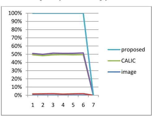
Fig 6. Bits per pixel comparison between CALIC and Proposed system
In compression part, two parameters (the PSNR and iterations in this case) are used to measure the degree of compression achieved. Each sample in the diagram is produced by setting up the compression algorithm to compress the image at a specified quality. For instance the quality parameter could be an integer ranging from 1 to 100. With quality 1 the algorithm would compress the image as much as possible,. With quality 100 the algorithm would compress the image with minimum or no loss of information. Proposed compression algorithm requires only small number of iterations to reach high PSNR value. Fig 4 Experimental result shows that asymptotic behavior of the proposed system is better than previous system. Iterations showing the number of execution which is required and trying to attain high compression metric in proposed method. Number of pixels measured in bits per pixel is compressed highly in proposed system. In state-of-the art system CALIC performance is less compared to ETC. Fig 6 showing Image ID is in X-axis and percentage of bpp is plotted in Y-axis. So Experimental results shows that proposed system ETC is compressed efficiently. In proposed system we can able to compress maximum number of bits in encrypted image. The compression efficiency of our proposed method applied to the encrypted images is comparedwith the lossless rates given by the latest version of CALIC, a benchmark of practically good lossless image codecs, a state-of-the-art lossless compression approach on encrypted images. In Fig. 7, we also compare the rate-PSNR performance of our compression method.For bit rates above 2 bpp, our method achieves even higher PSNR values than JPEG 2000. As bit rate drops, the PSNR gain over JPEG 2000 decreases. When the bit rate is below 2 bpp, the PSNR gain over JPEG 2000 diminishes and starts to become negative. When the bit rate is around 2.50 bpp, the PSNR gain can be over
0% 10% 20% 30% 40% 50% 60% 70% 80% 90% 100%
1 2 3 4 5 6 7
proposed
CALIC
10 dB for the input image. We also notice that the method of [scalable] seems to suffer from the problem of performance saturation for images with intensive activities such as Harbor, Bridge in [14].
Fig.7. Rate- PSNR comparison with CALIC and ETC
V. CONCLUSION
Image encryption and compression is an extremely important part of modern computing. This work proposed a novel idea for encrypting image and designed a practical scheme made up of image encryption and compression. In the encryption phase of the proposed system consists of, predictor called GAP, it had two potential improvements one is truly direction adaptive another one is from local to nonlocal prediction. Next is scanning method ZZRD is newly introduced here. It has performed better than traditional zigzag scan method. In permutation based image encryption, only the pixel positions are shuffled and the pixel values are not masked. The key generation process is unique and is a different process. The disturbance of the strong correlation among the adjacent pixels assures high security of the images. This is obtained with the help of permutation process. In Compression stage, modified floodfill algorithm and run length encoding is used. Newly introduced modified floodfill is considering circular shift directions to find neighbourhood pixels. By finding connected pixels similar regions can be grouped together. Due to simplicity of RLE, Compression performance could be increased. This method can be extended in trying to handle multiple images instead of single image by another predictor called GED, and another scanning method ZZSW, Image Encryption Using Block-Based Transformation Algorithm. Extending compression part by using another lossless compression algorithm.
REFERENCES
[1] Jiantao Zhou, Xianming Liu, Oscar ,and Yuan Yan Tang, “Designing an Efficient Image Encryption-Then-Compression System via Prediction Error Clustering and Random Permutation”, IEEE Transactions on Information Forensics and security, Vol.9, No.1, 2014.
[2] T. Bianchi, A. Piva, and M. Barni, “On the Implementation Of The Discrete Fourier Transform In The Encrypted Domain”, IEEE Trans. Inf. Forensics Security, Vol. 4, No. 1, pp. 86–97, 2009.
[3] Zekeriya Erkin, Thijs Veugen, Tomas Toft, L. Reginald, Lagendijk, “Generating Private Recommendations Efficiently Using Homomorphic Encryption and Data Packing”, IEEE Transactions on Information Forensics and security, Vol.7, No. 3, January 2012.
[4] Tiziano Bianchi, Alessandro Piva, Mauro Barni, “Composite SignalRepresentation for Fast andStorage-Efficient Processing of Encrypted Signals”, IEEE Transactions on Information Forensics and Security, Vol. 5, No.1, 2010.
[5] A. V. Subramanyam, Sabu Emmanuel, and Mohan S. Kankanhalli, “ Robust Watermarking of Compressed and Encrypted JPEG2000 Images”, IEEE Transactions on Information Forensics and security, vol.14, No. 3, June 2012.
[6] Demijan Klinc, Carmit Hazay, Ashish Jagmohan, Hugo Krawczyk, and Tal Rabin,” On Compression of Data Encrypted With Block Ciphers”, IEEE Transactions on Information Forensics and security, vol.58, No. 11, November 2012.
[7] Riccardo Lazzeretti, Mauro Barni, “Lossless Compression Of Encrypted Grey-Level And Color Images”, Department of Information Engineering (University of Siena) Via Roma 56, 53100, Siena, Italy.
[8] Xiao lin Wu, Nasir Menon, “CALIC- A Context Based Adaptive Lossless Image CODEC”, Department of Computer Science The University of Western Ontario, London, Ontario ,Canada N6A 5B7F Computer Science Department, Northern Illinois University, Dekalb, IL 60115, 1999.
0 10 20 30 40 50
CALIC rate
CALIC PSNR
proposed rate
Pandian Saraswathi Yadav Engineering College, Arasanoor, Sivagangai, Tamilnadu, India
[9] S Sankar and S Nagarajan, “ZZRD and ZZSW: Novel Hybrid Scanning Paths for Squared Blocks”International Journal of Applied Engineering Research ISSN 0973-4562 Vol. 9, No.21 pp. 10567-10582, 2014.
[10] Sesha Pallavi Indrakanti, P.S. Avadhani, “Permutation based Image Encryption Technique”, International Journal of Computer Applications (0975 – 8887) Vol.28, No.8, 2011.
[11] Samir Kumar Bandyopadhyay, Tuhin Utsab Paul, Avishek Raychoudhury, “Image Compression using Approximate Matching and Run Length”, (IJACSA) International Journal of Advanced Computer Science and Applications, Vol. 2, No. 6, 2011.
[12] Savan Kumar Oad, Karuna Markam, Aditya Kumar Bhatt , “Active Contours based Object Detection and Extraction using SPF Parameter”, International Journal of Computer Applications (0975 – 8887) Volume 64– No.8, February 2013.
[13] Shaimaa A. El-said, Khalid F. A. Hussein, & Mohamed M. Fouad, “Securing Image Transmission Using In- Compression Encryption Technique” International Journal of Computer Science and Security, (IJCSS), Volume (4).
[14] www.mathwork.org.
[15] Xinpeng Zhang, Guorui Feng, Yanli Ren, and Zhenxing Qian, “Scalable Coding of Encrypted Images”, IEEE Transactions on Information Forensics and security, vol.21, No. 6,june 2012.