Seismic Analysis of Multistorey Building with
Bracings using ETABS
Masood Ahmed Shariff1, Owais M1, Rachana C1, Vinu S1, AshishDubay B2
B.E. Student, Department of Civil Engineering, Rajeev Institute of Technology, Hassan, Karnataka, India1
Assistant Professor, Department of Civil Engineering, Rajeev Institute of Technology, Hassan, Karnataka, India2
ABSTRACT: Earthquake is the natural calamity known to mankind from many years, from the ancient time researches researched many ways to protect the buildings. There was a need to control the damage caused by earthquake to the both existing and newly to build structures. Many existing reinforced concrete buildings need retrofit to overcome deficiencies to resist seismic loads. Bracing is the most effective method which can be incorporated to the reinforced concrete buildings. Steel bracing is a highly efficient and economical method of resisting horizontal forces in a RC frame structure. Bracing has been used to stabilize laterally the tallest building structures. Braced frames can resist large amount of lateral forces and have reduced lateral deflection and thus reduces devastation.Steel bracing framework expands the stiffness and strength of the RC multi-storey building and reduces their deformation.In present study we have used an H shaped irregular building with 36m along X and 36 m along Y direction. Equivalent static linear seismic analysis is carried by using ETABS software, where the comparison of results is made between bare frame and X braced frame. The performance of the building is evaluated in terms of lateral displacement, base shear. The study is to be carried for the Zone ӀV and medium soil as specified in IS codes.
KEYWORDS: RC multi-storey building, Bracings, X braced system, Displacement, Base shear, Storey stiffness, Storey drift.
I. INTRODUCTION
India at present is fast developing country which requires demands in increase of infrastructure facilities along with the growth of population. Due to increased population, the demand of land for housing is increasing day by day. To fulfil the need of the land for housing and other commercial offices, vertical development that is multistory buildings are the only option. This type of development requires safety because these multistory buildings are highly susceptible to additional lateral loads due to earthquake and wind. In broad, as the elevation of building increases, its reaction to lateral loads increases. Multistory reinforced concrete buildings are vulnerable to excessive deformation, which necessitate the introduction of special measures to decrease this deformation. Seismic Retrofitting is a collection of mitigation technique for Earthquake engineering. It is of utmost importance for historic monuments, areas prone to severe earthquakes and tall or expensive structures.
Seismic Retrofitting Techniques are required for concrete constructions which are vulnerable to damage and failures by seismic forces. In the past thirty years, moderate to severe earthquakes occurs around the world every year. Such events lead to damage to the concrete structures as well as failures. In order to make multi-storey structures stronger and stiffer, the cross sections of the member increases from top to bottom of building this makes the structure uneconomical owing to safety of structure. Therefore, it is necessary to provide special mechanism that to improve lateral stability of the structure.
stiffen the frame structures against wind loads. A braced bent consists of usual columns and girders whose primary purpose is to support the gravity loading, and diagonal bracing members that are connected so that total set of members forms a vertical cantilever truss to resist the horizontal forces. Bracing is efficient because the diagonals work in axial stress and therefore call for minimum member sizes in providing the stiffness and strength against horizontal shear. Steel braced frame is one of the lateral load opposing frameworks in multistory structures. Bracings hold the structure stable by exchanging the horizontal loads, for example, earthquake or wind burdens down to the ground and oppose sidelong loads, in that way keep the influence of the structure. Steel bracing members in RC multistory building is conservative, simple to set up, involve less space and give obliged quality and inflexibility. There are various types of bracing systems like X bracing, V bracing, inverted V bracing, K bracing, diagonal bracing and so on.
X Braced System: An X-braced frame has bracing members in tension for both directions of loading, and if these are sized to yield before the columns or beams fail, ductility can be developed. Cross bracing is usually seen with two diagonal supports placed in an X shaped manner. Within any plane of bracing, the compression diagonal braces should balance the tension diagonal braces at each bracing level, in order to avoid tension braces contributing most to lateral resistance in one direction and compression braces in the other. This is to satisfy the general principle that the diagonal elements of bracings should be placed in such a way that the load deflection characteristics of the structure are the same for both positive and negative phases of the loading cycle.
II. LITERATUREREVIEW
Several researchers studied the effect of using the bracings in multi-storey reinforced cement concrete structures. A brief review of previous studies on effect of using the bracings as retrofitting structure on seismic behaviour of reinforced cement concrete structures is presented in this section and past efforts most closely related to the needs of the present work. [1] Amer Hassan and Shilpa Pal (2018) conducted the nonlinear time history and response spectrum analyses using Etabs-2015 software to study the influence of soil condition beneath the isolated base. The effects of soil flexibility are considered in the current study to examine the differences in spectral acceleration, base shear, story displacements, story drifts and story shear obtained following the seismic provisions of Indian standard code. [2] Z.A. Siddiqi et al (2014) has conducted the comparative study of five different types of bracing systems for the use in tall building in order to provide lateral stiffness and finally the optimized design in terms of lesser structural weight and lesser lateral displacement has been exposed. For this purpose a sixty storey regular shaped building is selected and analyzed for wind and gravity load combinations along both major and minor axes. [3] ChetanJaiprakashChitte (2014) has conducted Nonlinear static analysis, pushover analysis as the procedure is relatively simple and considers post elastic behavior.The effect of various types of concentric braces on the behavior of the structure is tried to be evaluated by using pushover analysis which can be used with due achievement of the economy taking care of safety. [4] A.R. Khaloo and M. Mahdi Mohseni (2008) had worked on nonlinear seismic behavior of RC Frames with RC Braces. This study focuses on evaluation of strength, stiffness, ductility and energy absorption of reinforced concrete braced frames and comparison with similar moment resisting frames and frames with shear wall.[5] M.A. Youssefa et al (2006) had worked on the efficiency of using braced RC frames is experimentally evaluated. Two cyclic loading tests were conducted on a moment frame and a braced frame. The moment frame was designed and detailed according to current seismic codes. A rational design methodology was adopted to design the braced frame including the connections between the brace members and the concrete frame.[6] J. P. Desai et al(2004) had worked on two-bay, six-story frame designed by limit state method subjected to artificial earthquake and bilinear hysteresis model was assumed for girders, elasto-plastic model was assumed for columns and simple triangular hysteresis model was assumed for reinforced concrete bracing. It is concluded that the inelastic seismic response of X and K braced concrete frames with intermediate bracing members is satisfactory.
Objective: To understand the behaviour of the structure under lateral loads. To provide the seismic resistant bracings to the RC structure and carry out the analysis.To know the displacement, base shear and story stiffness of the structure. And the comparison of the same is made between bare frame and braced frame.
III.METHODOLOGY
To achieve the objectives of study,it has been proposed to follow the following methodology. 1. Structuralplanning.
2. Modeling and analysis in ETABS.
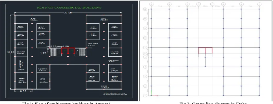
Plan Details: An H-shaped building in plan 36m in X direction and 36 m in Y direction with 5 storey is modeled in AUTOCAD and carried analysis using ETABS Software. The height of each story is kept as 3m in the structure with the plinth storey as 1.65m and the total height of the structure is 17.15m.
The building plan in AUTOCAD and centre line diagram in ETABS is shown below,
Fig 1: Plan of multistorey building in Autocad. Fig 2: Centre line diagram in Etabs
The 3D view of bare frame model and X braced frame model in ETABS are shown below,
Fig 5: 3-D view of bare frame (Model 1) multi storey building Fig 6:3-D view of X braced frame (Model 2) multi storey building
MODELDETAILS: 1. Geometrical Data
1. Type of Building: Commercial building
2. Building Dimensions:36 m along x & 36 m along y directions 3. Typical storey height: 3 m
4. No. of Storey: G+4
5. Foundation or plinth height: 1.65 m 6. Beam size: 0.3 m x 0.45 m
7. Column size: 0.3 m x 0.5 m
8. Slab thickness: building slabs-0.140 m, roof slab-0.120 m, stair slab-0.250 m 9. Wall thickness: 0.23 m
10. Steel brace: 2ISA (50 X 50 X 6) mm
2. Earthquake Data:
(Based on Indian seismic code, IS 1893-2002)
1. Seismic zone: Zone 4 (Table 2 of IS1893 – 2002(part1)) 2. Seismic Zone factor: 0.24 (Table 2 of per IS 1893:2002(part1)) 3. Importance Factor: 1.5 (Table 6 of per IS 1893:2002(part1))
4. Response Reduction Factor: 3 for ordinary moment resisting frames and 4 for concentrically braced frames ((Table 7 of per IS 1893:2002(part1))
5. Type of Soil: Medium Type 2
3. Material data:
1. Grade of concrete =M25 for beams and slabs, M30 for columns 2. Grade of steel =Fe415
4. Loading Data:
1. Dead load: It is defined automatically software defined (Table 2, IS 875 (Part 1):1987).
2. Live load: For this commercial building as per (Table1, IS 875 part 2), live load is taken as 5 kN/m2 on each floor and on roof 2 kN/m².
3. Floor Finish: 1.5kN/m²
4. Earthquake load in X and Y direction i.e. EQX and EQY. 5. Wall load = 11.143 kN/m
6. Parapet load = 1.425 kN/m
Load combinations based on IS 1893-2002
,
1. 1.5 (DL + LL ) 2. 1.2 (DL + LL ± EQX) 3. 1.2 (DL + LL ± EQY) 4. 1.5 (DL ± EQX) 5. 1.5 (DL± EQY) 6. 0.9 DL ± 1.5 EQX 7. 0.9 DL ± 1.5 EQY
5. Models:
Depending upon the provision of the concentric x bracings for the seismic analysis of the building, following models are considered.
MODEL 1: Bare frame
MODEL 2: Concentric X braced frame
6. Analysis in ETABS:
The seismic analysis should be carried out for the buildings that have lack of resistance to earthquake forces. Seismic analysis will consider dynamic effects hence the exact analysis sometimes become complex. However for simple regular structures equivalent linear static analysis is sufficient one. This type of analysis will be carried out for regular and low rise buildings and this method will give good results for this type of buildings.
IV.RESULTSANDDISCUSSIONS
The Equivalent static analysis is carried out and the parameters such as base shear or storey force, storey stiffness and maximum displacement are determined. Numbers of graphs are plotted and results are compared.
Graph1: Storey force or base shear in bare frame model Graph2: Storey force or base shear of X braced frame model
The maximum displacement in the building along X direction is obtained for the seismic load combination (1.2DL+1.2LL+1.2EQX) and along Y direction is obtained for the seismic load combination (1.2DL+1.2LL+1.2EQY). The least displacement is shown by Model No.2 which has the least displacement in X direction as X bracings are provided along X direction. The reduction in X direction is about 45.66%. Model No.2 shows least displacement in Y direction as x bracings are provided in Y direction. The reduction in displacementin Y direction is about 37.21%.
[2]Storey force or Base shear:Base shear is an estimate of the maximum expected lateral force that will occur due to seismic ground motion at the base of a structure or the seismic force at base of the building is called the base shear
.
The analysis results of base shear of the bare frame building (Model No.1) and X braced frame building (Model No.2) in both X and Y direction i.e. for combinations (1.2DL+1.2LL+1.2EQX) and (1.2DL+1.2LL+1.2EQY)respectively is as follows,
Graph 3: Storey force or base shear in bare frame model Graph 4: Storey force or base shear of X braced frame model
From the above storey shear graph (Graph.3) (Model No.1) it is clear that, the Storey Shear is decreased as height of the building increased and reduced at top floor in all the building models subjected to seismic loads considered. The storey shear is maximum at the base i.e. at the lower stories. And the maximum storey shear value for the bare frame
0 20 40 60 M a x D is p la c e m e n t (m m )
DISPLACEMENT ALONG X DIRECTION BARE FRAME BRACED FRAME 0 10 20 30 40 50 M a x D is p la c e m e n t (m m )
DISPLACEMENT ALONG Y DIRECTION BARE FRAME BRACED FRAME 0 2000 4000 6000 8000 10000
Storey1 Storey2 Storey3 Storey4 Storey5
S to r e y F o r c e (k N )
STOREY FORCES OF BARE FRAME
X direction Y direction 0 2000 4000 6000 8000 10000 12000
Storey1 Storey2 Storey3 Storey4 Storey5
S to r e y fo r c e (k N )
STOREY FORCES OF X BRACED FRAME
Xdirection
model at storey1 along X direction for the load combination (1.2DL+1.2LL+1.2EQX) is 8361.850 kN and along Y direction for the load combination (1.2DL+1.2LL+1.2EQY) is 6594.697 kN
.
From the above storey shear graph (Graph.4) for (Model No.2) it is clear that, the Storey Shear is decreased as height of the building increased and reduced at top floor in all the building models subjected to seismic loads considered. The storey shear is maximum at the base i.e. at the lower stories. And the maximum storey shear value for the bare frame model at storey1 along X direction for the load combination (1.2DL+1.2LL+1.2EQX) is 9663.475 kN and along Y direction for the load combination (1.2DL+1.2LL+1.2EQY) is 7782.880 kN.
[3] Storey stiffness:
It
is the rigidity of the storey which resists the deformation in response to lateral force. The analysis results of storey stiffness of the bare frame building and braced frame building in X direction i.e. for combination (1.2DL+1.2LL+1.2EQX) andthe analysis results of storey stiffness of the bare frame building and braced frame building in Y direction i.e. for combination (1.2DL+1.2LL+1.2EQY)is as follows,
Graph 5: Storey force or base shear in bare frame model Graph 6: Storey force or base shear of X braced frame model
Graph No. 5 shows that Model No.1 i.e. bare frame has least stiffness than the Model No.2 i.e. X braced frame. The Storey stiffness is decreased as height of the building increased and reduced at top floor in all the building models subjected to seismic loads considered. Storey stiffness is maximum at the base i.e. at the lower stories. And the maximum storey stiffness value for the bare frame and braced frame model at storey1 along X direction is 668232.719 kN/m and 1637012.503 kN/m respectively.
Graph No. 6 shows that Model No.1 i.e. bare frame has least stiffness than the Model No.2 i.e. X braced frame. The Storey stiffness is decreased as height of the building increased and reduced at top floor in all the building models subjected to seismic loads considered. Storey stiffness is maximum at the base i.e. at the lower stories. And the maximum storey stiffness value for the bare frame and braced frame model at storey1 along Y direction is 426096.073 kN/m and 1139967.615 kN/m respectively
.
[4]Storey drift:Storey drift is the drift of one level of a multistory building relative to the level below. Interstory drift is the difference between the roof and floor displacements of any given story as the building sways during the earthquake, normalized by the story height.The analysis results of storey drift of the bare frame and braced frame building in X direction i.e. for combination (1.2DL+1.2LL+1.2EQX) and the analysis results of storey drift of the bare frame and braced frame building in Ydirection i.e. for combination (1.2DL+1.2LL+1.2EQY)is as follows is as follows,
0 1000000 2000000 3000000 4000000 5000000 S to re y S ti ff n es s (k N /m )
STOREY STIFFNESS ALONG X DIRECTION BARE FRAME BRACED FRAME 0 500000 1000000 1500000 2000000 2500000 3000000 S to re y S ti ff n es s (k N /m )
STOREY STIFFNESS ALONG Y DIRECTION
BARE FRAME
Graph 7: Storey force or base shear in bare frame model Graph 8: Storey force or base shear of X braced frame model
Graph No.7 shows that model No.1 i.e. bare frame shows more drift and least drift is shown by concentric X braced frame. Model No.2 shows least displacement in X direction as X bracings are provided. From the analysis result of drift we can see model No.2 i.e. concentric X braced model offers least drift among both the models.
Graph No.8 shows that model No.1 i.e. bare frame shows more drift and least drift is shown by concentric X braced frame. Model No.2 shows least displacement in Y direction as X bracings are provided in y direction.
From the analysis result of drift, we can see model No.2 i.e. concentric X braced model offers least drift among both the models.
V. CONCLUSION
The analysis of the H shaped Reinforced Concrete framed building subjected to the seismic loads with and without the consideration of X bracings under the seismic zone consideration was carried out in ETABS software. The following conclusions are made.
The maximum storey displacement of the building is reduced by the use of X type bracing system. Displacement value decreases from top storey to base. It is found that the reduction in the displacement along X direction is about 45.66% and similarly along y direction the reduction is about 37.21%.
Storey shear is higher for building with X brace than the bare frame building. It is found that the increment in the storey shear along X direction is about 13.46% which is equal to 9663.475 kN and similarly along Y direction the increment is about 15.26% which is equal to 7782.88 kN.
Storey stiffness is higher for building with X brace than the bare frame building. It is found that the increment in the storey stiffness along X direction is about 57.39% which is 3842461.995 kN/m in braced frame at the base and similarly along Y direction the increment is about 53.70% which is equal to 2644207.615 kN/m in braced frame at the base.
The storey drift of the building is reduced by the use of X type bracing system. Drift value decreases from top storey to base. Storey drift is maximum at intermediate storey levels and minimum the top storey. The minimum value for X braced building is 1.237 mm in X direction and 0.929 mm in Y direction.
Building with X type of bracing is found to be safe and most effective against the seismic loading.
REFERENCES
[1]. Z.A. Siddiqi, Rashid Hameed, UsmanAkmal, “Comparison of Different Bracing Systems for Tall Buildings” Int. Jr. Engg. & Appl. Sci. Vol. 14, Jan., 2014.
[2]. Viswanath K.G., Prakash K.B. and Anant Desai, “Seismic analysis of steel braced RC frame” International Journal of Civil and Structural Engineering Volume 1, No 1 in the year 2010.
[3]. IS: 1893 (Part 1): Indian Standard Criteria for Earthquake Resistant Design of Structures, Bureau of Indian Standards, New Delhi (2007). [4]. IS: 456: Indian Standard Code of Practice for Plain and Reinforced Concrete, Bureau of Indian Standards, New Delhi (2000).
0 0.5 1 1.5 2 2.5 3 3.5 4
D
r
ift
in
m
m
DRIFT ALONG X DIRECTION
BARE FRAME
BRACED FRAME
0 0.5 1 1.5 2 2.5 3 3.5
D
r
ift
in
m
m
DRIFT ALONG Y DIRECTION
BARE FRAME
[5]. IS: 875 (Part 1): Code of Practice for Design Loads (Other than Earthquake) For Buildings and Structures. Part 1: Dead Loads (Second Revision) (1987).
[6]. IS: 875 (Part 2): Code of Practice for Design Loads (Other than Earthquake) For Buildings and Structures. Part 2: Imposed Loads (Second Revision) (1987).
[7]. IS: 875 (Part 3): Code of Practice for Design Loads (Other than Earthquake) For Buildings and Structures. Part 3: Wind Loads (Second Revision) (1987).
[8]. VinodHosur’s text book titled “Earthquake Resistant Design of Building Structures”2nd Ed,reprinted in the year 2013. [9]. V.N. Vazirani and M.M. Ratawani’s “Analysis of structures” 10th Ed., Khanna Publishers in the year 1985
[10]. Amer Hassan and Shilpa Pal, “Nonlinear time history analysis for isolated soil base” in the year 2018.
[11]. A.R. Khaloo and M. Mahdi Mohseni had worked on nonlinear seismic behavior of RC Frames with RC Braces in the year (2008). [12]. M.A. Youssefa et al, had worked on the efficiency of using braced RC frames is experimentally evaluated in the year 2006. [13]. Bracing for Steel Buildings by Dr. Ibrahim Fahdah -Damascus University source from google.com in the year 2011-2012.