Grain/Pore Microstructure-based Evaluation Method for Variation
of Mechanical Property of Graphite Components in the HTGR
Taiju Shibata and Masahiro IshiharaJapan Atomic Energy Research Institute, Ibaraki-ken, Japan
A B S T R A C T
Since oxidation will degrade the mechanical property of graphite components in high temperature gas-cooled reactors (HTGRs) during reactor lifetime, one of the crucial subjects to maintain the structural integrity of the components is the measurement of the oxidation damage in in-service inspection. It is important to examine inner porous condition of the components, such as pore size and porosity, because the mechanical properties of graphite highly depend on the condition, as well known. Ultrasonic Testing (UT) is an important non-destructive method to detect internal flaws inside a body and is widely applied not only for metallic but also porous ceramic components. UT is, therefore, thought to have a potential to examine the porous condition inside the graphite components by non- destructive way. An analytical study about ultrasonic wave propagation characteristics for oxidized graphite was carried out to evaluate the oxidation damage by the UT method. In this study, a wave-pore interaction model was tried to apply to oxidized graphite, and it was found ~ that the consideration of pore shape change with proceeding of the oxidation was a crucial factor to evaluate the ultrasonic wave propagation characteristics. In this paper, the applicability of the analytical model to the oxidized graphite is discussed on the basis of the analytical results of the oxidation-induced degradation of the Young's modulus.
I N T R O D U C T I O N
The core internal components of high temperature gas-cooled reactors (HTGRs) are made of graphite material owing to its excellent thermal resistibility. The high temperature engineering test reactor (HTTR), which is now being in a power-up test in the Japan Atomic Energy Research Institute, is a kind of gas-cooled and graphite moderated test reactor with a themml output of 30MW[ 1]. The integrity of the graphite components will be checked in in-service inspection during the reactor lifetime. The mechanical strength of the components will be inspected by using graphite surveillance test specimens loaded in the core. The surface of tile components will be checked visually by a TV camera which resists radioactivity[2].
One of the serious problems of the graphite components is degradation of mechanical properties by oxidation. It is caused by a small amount of corrosive impurity gases in the primary coolant during normal reactor operation as well as by invaded water and/or air at an accident. It is well known that mechanical properties of graphite are remarkably decreasing with increasing of oxidation damage. The change of the properties had been investigated experimentally and expressed by empirical formula as a function of the porosity of graphite[3]. Pores are generally located among the grains of a polycrystal body. On the viewpoint of structural integrity of the graphite components, it is important to examine the inner porous condition and to evaluate the oxidation damage in an in-service inspection to support the result of the surveillance test and the TV camera inspection.
Ultrasonic testing (UT) has been widely used as a non-destructive method to detect internal flaws. Recently UT is applied to porous ceramics including graphite materials[4-8]. Ultrasonic wave propagation characteristics in ceramics are, owing to its porous structure, quite different from those in metallic materials. Since the characteristics depend on the inner porous condition, it is thought to be possible to evaluate the oxidation damage of the graphite components by applying the UT method. Takatsubo et al. was proposed an ultrasonic wave propagation model that theoretically enables us to estimate the inner porous condition, such as the mean pore size and the porosity, of porous ceramics from a propagated ultrasonic wavefonn[9, 10]. The present authors have been investigating a new approach combining the UT model and fracture mechanics to evaluate, non-destructively, the mechanical strength of the IG-110 graphite, which is fine-grained isotropic nuclear grade graphite used in the HTTR core components[7, 8, 11]. It is thought the ultrasonic wave propagation characteristics will change with proceeding of the oxidation which affects on the inner porous condition. If the UT model is applicable to the oxidized graphite components, we can examine inner porous condition and, then, can evaluate the degradation of mechanical properties by non-destructive way. This paper
SMiRT 16, Washington DC, August 2001 Paper # 1114
describes evaluation of the mechanical property of the oxidized graphite by the UT model with considering the change of porous condition.
ANALYSIS
An ultrasonic wave propagation model in porous ceramics body was proposed by Takatsubo et al. taking account of wave-pore interaction process[9, 10]. In the model, ultrasonic waves are propagated in a porous body through interactions with pores. If an ultrasonic wave comes into collision with a spherical shaped pore, the wave will be scattered by the pore or will go forward creeping through pore edge as shown in Fig. 1 [9]. The creeping wave has a time delay,
At,
in comparison with a direct wave, given by the following equation[9].A t - Lp
r
where Vc and Vp are the velocities of the creeping and direct waves, r is the mean pore radius and Lp is the propagation length for the creeping wave around a pore. It is assumed in this model that spherical pores with a radius r are located homogeneously at a three-dimensional regular interval in the porous body. The propagated waveform through a great number of pores in the body can be calculated by a statistical method with cumulating of the time delay and the collision probability for the pores. The waveform, as a result, can be expressed in the Gaussian function as a function of propagation time[9].
Direct wave : 1-f
H f---q I e ~ ~
Collision :f2:>._~(~_...l) C r e e p i n g ~ , r ~ w a v ' e ~ At .J..,
Scattering loss -'~ Time delay
: (1-c)f ~ Pore
Fig. 1 Ultrasonic wave propagation model in porous body[9].
(f is a probability of collision for an incident wave on a pore)
The Young's modulus of the porous body, E, can also be evaluated through the apparent velocity of the wave calculated by the propagation model. It is expressed by the Young's modulus of an ideal body with no pore,
Ej,
as follows[9]:where
E / E~ - ( 1 - q~)/{1 + 3~b(n / a - 2 ) / 8 } 2
a=v /v
P
(2)
and ~ is porosity of the porous body. The a value was assumed as 0.71 for the IG-110 graphite on the basis of experimental results of alumina specimens[10]. Typical mechanical properties of the IG-110 graphite are~ listed in Table 1[11].
B ~..
w0-w
w0
The burn-offB can be also expressed by porosities ¢~ 0 and ¢~,
B = I - ~
1- 0
before and after the oxidation, respectively:
(3)
(4)
Table 1 Tipical mechanical properties of IG-110 graphite[11].
Density (kg/m 3) 1.78× 10³
Porosity 0.212
Mean grain size (/x m) 20
Young's modulus (GPa) 9.8
Tensile strength (MPa) 24.5
E X P E R I M E N T
The IG- 110 graphite specimens were oxidized uniformly to investigate the change of porous condition after the oxidation. The specimens were heated up at about 4000(3 in the air condition so as to be oxidized uniformly[12]. Maximum burn-off was about 18%.At this condition, pores are thought to be distributed homogeneously inside the body even after the burn-off, as well known. In general, pores are classified as the open pore, located at the surface of the body, and the closed pore, located inside the body. The mean pore radius was measured by the mercury porosimetry method[ 13]. By this method, we can measure the mean pore radius for open pores. The pore radii, ranged from 0.007 to 5 /z m, were measured by varying the pressure of mercury.
R E S U L T S AND D I S C U S S I O N S
Porous Condition Change with Burn-off
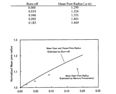
Table 2 Burn-off induced pore radius change measured by mercury porosimetry method[13].
Burn-off Mean Pore Radius (/2 m)
0.000 1.299
0.019 1.324
0.046 1.351
0.092 1.401
0.183 1.449
1.3
° ~ "0
0
~- 1.2
0
0
0
.__ 1.1 E
0 Z
f
1.0 0.00
Mean Open and Closed Pore Radius
(Estimated by Burn-off)
o
I I I I
0.05 0.10 0.15 0.20
Burn-off
0.25
Fig.2 Change of mean pore radius as a function of bum-off.
Analytical Result with Spherical Pore Condition
Sato et al. proposed, through experimental approach, an empirical formula to express the degradation as a fimction of the burn-off[3]. Figure 3 shows the degradation of the Young's modulus of the IG-II0 graphite. Their experimental data and proposed empirical formula[3] are shown in this figure. By their formula, the degradation of Young's modulus of the IG- 110 graphite is expressed as follows[3]:
E / E o - e x p ( - 6 . 8 6 B ) (5)
where
Eo
is the initial value of the Young's modulus corresponding to no bum-off condition. In Fig. 3, the dotted line corresponds to the empirical formula.1.2
Analysis (Sperical Pore)
,
/
0 . 8 • ....
o
u.l
~ 0.6 - u.!
0.4
0.2
...
Expe/riment[3] /
... ...
"Q
Empirical F o r m u l a [ 3 ] ~"
0 I I I I
0 0.02 0.04 0.06 0.08
Burn-off
0.1
Fig.3 Degradation o f Young's Modulus o f IG-110 graphite as a function of bum-off.
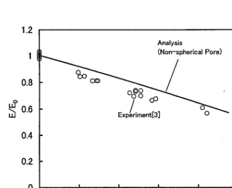
A n a l y t i c a l R e s u l t w i t h N o n - s p h e r i c a l P o r e C o n d i t i o n
Since the propagated ultrasonic waveform is analyzed by the cumulating of the time delay of the creeping wave in comparison with the direct wave, it is expected that the time delay of the creeping wave, expressed in the Eq. (1), depends directly on the length of propagation path around the pore. If the pore geometry deviate from a sphere, the Young's modulus of the pore body in Eq, (2) can be rewritten as follows[9]:
E / E i - (1 - ~)/{1 + 3 ¢ ( z f l / cr - 2)
/
8} 2 (6)where
,B - 4Lp / ( 2 ~ )
The fi' e x p r e s s e s the deviation of pore shape from sphere. The effect of the change of pore shape on the d e g r a d a t i o n of the Young's modulus can be considered in Eq. (6).
For no burn-off condition of the IG-110 graphite, we h a d a l r e a d y s h o w n t h a t the m e c h a n i c a l s t r e n g t h of the IG-110 g r a p h i t e could be e v a l u a t e d by the a n a l y s i s of the u l t r a s o n i c wave p r o p a g a t i o n model w i t h a s s u m i n g spherical pore shape[8]. In this analysis the ~/ce value was set as 1.41 for s p h e r i c a l pores. Considering the pore shape change, this value should be c h a n g e d with proceeding of the burn-off. The change of the /5./' c~value can be estimated as a fimction of the porosity from both experimental and analytical studies about aluminum specimens. If the relationship between the ,6/a~ value and porosity is applicable to the oxidized IG-110 graphite, the degradation of the Young's modulus can may appropriately evaluated by the UT propagation analysis. Since the relationship is thought to depend on the materials, we tried to apply it to the IG-110 graphite by multiplying a factor to the relationship for aluminum as shown in Fig. 4. The factor was decided on the basis of the , 6 / a value at 0.212 of porosity which corresponding to no burn-off condition of the IG-110 graphite. The fi'/~ value at this porosity of aluminmn[10] was reduced by the factor so as to fit the value of the IG-
110 graphite at the no burn-off condition.
relationship between the pore shape and porosity for the oxidized IG-110 graphite may be slightly different from that for aluminum. This is thought to be a reason of the slight difference in this figure. It is, therefore, necessary to examine the oxidation-induced pore shape change exactly for more precise analysis.
4.5
4 . 0 "
3.5
3 . 0 -
2.5 -
2.0 -
1.5
A l u m i n u m [ 1 0 ] I .,,,,,,~," .,..,...,-" ,.o,,. I~o ~Q
. . ~ . ~ . . - ~ " " ... I G - 1 1 0
/ Fact°T_..~
1 . 0 I I I I ,
0.20 0.22 0.24 0.26 0.28 0.30
Porosity
Fig. 4 Change of # / c~ value as a function of porosity for analysis at non-spherical pore condition.
1.2
0.8
o
~ 0.6
~ J
0.4
0.2
A n a l y s i s
( N o n - s p h e r i c a l Pore)
I I I I ,.
0 0.02 0.04 0.06 0.08 0.1
Burn-off
C O N C L U S I O N S
In order to evaluate the oxidation damage of the graphite components in HTGRs, the applicability of the UT method was studied analytically. The oxidation-induced degradation of the Young's modulus of the IG-110 graphite, caused by the change of inner porous condition, was analyzed by the ultrasonic wave propagation model. In the analysis, the porosity and pore size change was taken into consideration in the wave-pore interaction process. It is concluded from this study that the modeling of pore shape change with proceeding of the oxidation is an important point to evaluate the ultrasonic wave propagation characteristics, and furthermore the degradation of the Young's modulus can be evaluated appropriately by the modeling. It is supposed, therefore, the UT method has a potential as a promising in-service inspection technique for the graphite components in HTGRs. Since the ultrasonic wave propagation properties are thought to depend on the measuring condition, there are several subjects to be resolved to promote the UT on the graphite components in the future. It is necessary to define the measuring condition to carry out the UT in the radioactive field, such as a recovery of couplant and a radioactive resistive probe.
A C K N O W L E D G E M E N T S
The attthors are greatly indebted to T. Takahashi of JAERI for preparation of the oxidized graphite specimens and to T. Konishi ofTOYO TANSO Co. for measuring the mercury porosimetry data. The authors are also thankful to T. Iyoku and Dr. K. Hayashi of JAERI for their useful suggestions and encouragement.
N O M E N C L A T U R E
B
C
E Ei f Lp
r
V~, Vp W
/J
At= burn-off
= creeping rate of initial wave at a pore = Young's modulus
= Young's modulus of an ideal body with no pore = wave-pore collision probability
= propagation length around a pore = pore radius
= ultrasonic velocity of the creeping and incident waves = weight of graphite body
=
vJv,,
= 4 Lp/(2 zc r)
= time delay of a creeping wave = porosity
Subscripts
0 = value at no bum-off condition
R E F E R E N C E S
1. Saito, S. et al., "Design of High Temperature Engineering Test Reactor (HTTR)," JAERI 1332, 1994.
2. Ishihara, M., Shibata, T. and Kikuchi, T., "Study on in-service visual inspection using TV camera for core support graphite components in the HTTR," Trans. of 7th Int. Conf. on Nucl. Eng. (ICONE-7), Tokyo, Japan,
1999.
3. Sato, S. Hirakawa, K., Kurumada, A., Kimura, S. and Yasuda, E., "Degradation of Fracture Mechanics Properties of Reactor Graphite Due to Burn-off," Nucl. Eng. and Des, 118, pp.227-241, 1990.
4. Ishihara, M., Iyoku, T., Shiozawa, S,, and Kambe, M., "Application of ultrasonic testing as acceptance test for the graphite component of HTTR," Trans. of 13th Int. Conf. on Structural Mechanics in Reactor Teclmology (SMiRT13) Vol.I, pp.575-580, Porto Alegre, Brazil, 1995.
5. Ishihara, M,, Shibata, T. and Hanawa, S., "Preliminary Investigation on the In-service Inspection of Graphite Components in the HTTR Using Ultrasonic Testing," Trans. of 15th Int. Conf. on Structural Mechanics in Reactor Technology (SMiRTI5), Vol.III, pp. 143-150, Seoul, Korea, 1999.
M 93-003, 1993. [in Japanese]
7. Shibata, T. and Ishihara, M., "Analytical and Experimental Study on Ultrasonic Characteristics of Graphite Material," Proc. of Ira. Symp. of Carbon, IP11-03, pp.642-643, Tokyo, Japan, 1998.
8. Shibata, T. and Ishihara, M., "Ultrasonic Signal Characteristics by Pulse-echo Technique and Mechanical Strength of Graphite Materials with Porous Structure," Nucl. Eng. and Des, in Printing.
9. Takatsubo, J. and Yamamoto, S., "Study on the Propagation Mechanism of Ultrasonic Waves in Porous Ceramics (lst Report, Theory)," Trans. Jpn. Soc. Mech. Eng., 60-577(A), pp.2126-2131, 1994. [in Japanese] 10. Takatsubo, J. and Yamamoto, S., "Study on the Propagation Mechanism of Ultrasonic Waves in Porous
Ceramics (2nd Report, Experimental Confirmation of the Theory)," Trans. Jpn. Soc. Mech. Eng., 60-577(A), pp.2132-2137, 1994. [in Japanese]
11. TOYO TANSO Co., "Isotropic Graphite Technical Data," 1998. 12. Takahashi, T., Private communication.
![Fig. 1 Ultrasonic wave propagation model in porous body[9].](https://thumb-us.123doks.com/thumbv2/123dok_us/1484848.1181667/2.596.177.397.309.405/fig-ultrasonic-wave-propagation-model-porous-body.webp)